Category: General Operation

Articles that discuss general field sprayer operation and productivity factors

  • ExactApply Primer

    ExactApply Primer

    ExactApply is an application system capable of PWM, introduced by John Deere in August, 2017, with its first customer field season in 2018. ExactApply offers several unique features that differentiate it from the existing systems. Here is a brief description of its major components and capabilities:

    Nozzle Body Design:

    • The body contains a turret with six numbered nozzle locations, all pointed down, and two solenoids, one on either side of the body. Three nozzle locations are on short feeds (locations 1, 2, and 3), whereas the remainder are on long feeds (4, 5, and 6). The front locations and left solenoid is called “A”, whereas the right solenoid and rear location is “B”.
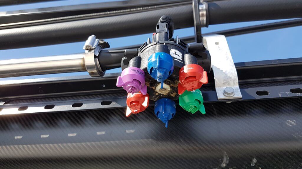
    ExactyApply nozzle body
    • Nozzles are paired so that A or B or both are capable of spraying at a time, depending on the selected mode. Pairs are 1 & 4, 2 & 5, and 3 & 6. The operator manually rotates the desired nozzle pair into position.
    • When a short feed (1, 2, or 3) is placed at the front of the body, the system is in Separated Mode. In this mode, the left solenoid controls the front nozzle and the right solenoid control the rear nozzle. Either or both can be used, in pulsing (PWM) or conventional mode, selected through the monitor.
    • When a long feed (4, 5, or 6) is placed at the front, the body is in Combined Mode. Now, all flow from the right and left solenoid can only exit the front nozzle. Very high flows are achievable in Combined Mode, making it suitable for liquid fertilizer application. It may not have other practical applications in Western Canada.
    View from left side of body (solenoids removed). Turret position #4 (tall feed) is in front, and #1 (short feed) is in back, placing the body in Combined Mode.
    • In Pulsing Mode, each solenoid pulses at 15 Hz, meaning it completes 15 open-and-close-cycles per second. The A and B solenoid timing is offset by 180 degrees, so that the B nozzle is in the middle of its on-cycle when the A nozzle is in the middle of its off cycle. In combined mode, this means that the system operates at 30 Hz.
    • Adjacent bodies are also 180 degrees out of sync with each other, similar to Capstan, Raven, and TeeJet bodies, so that whenever a nozzle is off, its adjacent partners are on (when operating at 50% DC and above). Another way of saying this is that all even-numbered bodies act together, and all odd-numbered bodies act together but half a cycle later. This results in a blended pulse that prevents skips.
    Plunger assembly inside solenoid. Black plastic portion can be removed, exposing poppet and spring.
    • The proportion of each cycle that the solenoids are open is known as the duty cycle (DC). At 100% DC, the valves are always open. At 50% DC, the valves are open 50% of the time. The minimum DC allowed by the system in default is 25%. This can be lowered to a smaller value within the monitor.
    Opened plunger assembly showing tip of poppet (right) and seat (left)
    Poppet inside plunger assembly is pulled back by magnet inside solenoid 15 times per second
    • DC is closely related to the flow rate of the nozzle. There are two ways of looking at this. An 08 sized tip operating at 40 psi will have a flow rate of 0.8 US gpm at 100% DC, about 0.4 US gpm at 50% DC, and close to 0.2 US gpm at 25% DC. This feature is primarily useful when sprayer speed is changed, requiring new flow rates without a change in spray pressure.
    • Pulsing Mode is not available for nozzles sized smaller than 02, or for air-induced tips.
    • Pulsing can be disabled to allow the use of air-induced or other tip technologies that may not function well when pulsed. This is called AutoSelect Mode.

    AutoSelect Mode:

    • AutoSelect Mode (“Auto Mode” in 4600 monitor) can be used to achieve three unique flow rates. “A” alone, “B” alone, or “A” & “B”. When properly staggered, a travel speed range similar to Pulsing Mode can be achieved, although pressure will rise within each nozzle as travel speeds increase, as in a conventional system.
    • In AutoSelect Mode, the user selects a tip for position A, and an incrementally larger tip for position B. The monitor requires that the user inputs minimum and maximum pressures for A, B, and A&B. Travels speeds corresponding to these tip and pressure choices are calculated, and the monitor warns the user when speeds don’t overlap. The user either changes minimum and maximum spray pressures, or selects a different sized tip to eliminate the gap.
    • AutoSelect Mode is useful when a certain specific tip is required which is not compatible with Pulsing Mode, for example drift protection with air-induced tips.

    Pulsing Mode Nozzle Selection

    At this time, John Deere nozzles best suited to the ExactApply’s Pulsing Mode are the LDM, LD, LDX, and 3D. Of these, the LDM most closely represents the spray quality of the LDA and ULD that John Deere operators are accustomed to. The remainder are considerably finer.

    ASABE spray qualities for Low-Drift Max (LDM) tips. Being Very Coarse at lower pressures, applicators are advised to use higher spray pressures (50 to 70 psi) when coverage is important.
    ASABE spray qualities for Guardian (LDX) tips. Note that the smaller sizes (03, 04, 05) produce finer sprays and will require pressures below 40 psi to have any reasonable drift reduction.
    ASABE spray qualities for 3D tips. As with LDX, the smaller sizes (03, 04, 05) produce finer sprays and will require pressures below 30 psi to have any reasonable drift reduction. Such low pressures may narrow the spray pattern.
    ASABE spray qualities for Low-Drift (LD) tips. As with LDX, the smaller sizes (03, 04) produce finer sprays and will require pressures below 40 psi to have any reasonable drift reduction.
    ASABE spray qualities for the Low-Drift Twin (LDT). Comprised of two same-sized LD tips assembled in a TwinCap.

    Proper sizing for PWM requires that tips be sized for about 20 to 40% extra capacity. In other words, at expected average travel speeds, the pulsing duty cycle should be approximately 60 to 80%. The following chart has a highlighted column at 70% duty cycle for that reason. Assuming an ExactApply operator expects to apply 5 gpa and travel at 15 mph on average, possible nozzle options (highlighted in yellow) are:

    03 at 60 psi

    04 at 30 psi

    05 at 20 psi

    06 at 15 psi
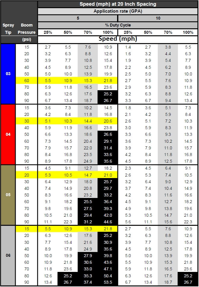
    Calibration chart for PWM systems. Nozzles are sized at about 70% Duty Cycle (grey column). Options for 5 gpa at 15 mph are highlighted yellow. Black highlights represent speeds >25 mph, not available.

    The best choice will likely be either of the first two options, as the third and fourth have spray pressures which are probably too low for good nozzle performance. The decision would depend on the spray quality obtained for each of the remaining two options.

    Of course, spray pressure can be altered to suit the operator’s spray quality requirements. This merely affects the available speed range as well as the DC at which the system operates at a given target speed, possibly affecting Pulsing Mode utility.

    The row of speeds adjacent to the selected nozzle and pressure identifies the approximate travel speed range that can be expected, from 25 to 100% DC.

    It’s important to know your current DC to be sure the system is operating properly, and also to take full advantage of turn compensation features. We’ve described a way to place a DC display module on your home screen here.

    Download an Excel version of this chart here.

    The application volume can be changed to suit the specific use, the chart’s speed values are updated automatically. Make sure the nozzle spacing at the top left is correct for your sprayer

    Pressure Drop across Solenoids

    PWM solenoids represent a restriction to flow, and may cause a pressure drop. John Deere has published the pressure drop, and it is shown in the above chart (download version only). The pressure drop is fairly low, only 2 psi for an 04 tip operating in separated mode at 40 psi. For an 06 tip, the drop is 3 psi, and for an 08, it’s 6 psi. a #10 tip has a 10 psi drop at 40 psi. These pressure drops must be added to the operating pressure of the sprayer. Pressure drop is important because the LDX, LD, and 3D tips will be operated at low pressures to obtain coarse sprays for drift protection. Operating an 08 tip at 20 psi (at which pressure it has s drop of 3 psi) will result in in a tip pressure of 17 psi. Since we are at the low end of a nozzle’s operating range, pattern stability may be compromised when the drop is not taken into account.

    Why 70% Duty Cycle?

    An operator of any PWM system needs to know their current duty cycle. On ExactApply, a module can be installed on the home screen that provides a visual display. We show how to do this here.

    There are five main reasons a nozzle should be sized to run at approximately 70% DC. The first is to provide speed flexibility. An operator may need to speed up somewhat, but usually not more than 30%. On the other hand, slowing down is much more common to accommodate challenging terrain, and a factor of two to three is possible (from 70% DC to 25% DC).

    Secondly, drift reduction through lower spray pressure usually requires less speed due to the associated lower flow rate. With some DC room to spare, the loss of flow can be corrected without requiring a speed change.

    Thirdly, spot spraying at a slightly higher rate is possible, again through DC alone.

    Fourth, Nozzle Rate Boost of up to 25% for up to six nozzle locations is possible within the monitor, but only if the system is operating at 75% DC or less.

    Finally, turn compensation, during which the outside boom travels faster than the tractor unit and the inside boom slower, requires this additional capacity. More on turn compensation here.

    AutoSelect Mode Nozzle Selection

    AutoSelect Mode allows for three flow rates to be used in succession: A, then B, the AB. The key to success is to use small size increments between A and B, and to use tips that have a wide pressure range.

    In the example below, the A location was an 02 tip and the B was an 03, for a total of 05. Pressure was not allowed to drop below 30 psi to retain good patterns. Pressure at switch over to the next largest flow rate therefore needed to be 80 psi to make the moves possible without pressure gaps resulting in over-application. As a result, the spray quality can be expected to fluctuate three times as the sprayer accelerates through A, B, and AB in succession.

    Nozzle selection should seek to emphasize the middle of the pressure range of either B or AB to avoid unnecessary fluctuations.

    Spray pressure and travel speed as Auto Mode moves through A, then B, then both A&B

    Download an Excel sheet that assists in nozzle selection for Auto Mode here.

    Maintenance

    A maintenance kit comes with each ExactApply sprayer. It contains two spare plunger assemblies, clips, and pins, as well as a brush, an O-ring picker, and a torque driver.

    Maintenance kit

    The ExactApply body is fairly easy to take apart for servicing. Hair pins at the back of the unit secure each solenoid, and both pull out easily. The plunger assembly can be disassembled without tools. Take care not to drop the poppet spring!

    Reassembly of the plunger requires the use of the torque driver fitted with a 17 mm socket, included in the kit. Do not over-tighten the plastic component.

    Aside from the manual rotation of the turret to select a different nozzle combination, the only moving part in the ExactApply body is the poppet in the plunger assembly. This piece is the valve that controls flow rate, and opens and closes 15 times per second whenever pulsing mode is on, moving like a piston in a cylinder. Debris (sand, fertilizer crystals, etc.) can interfere with the seal of the poppet against its seat, and good filtration is important.

    In the first generation, metal flakes began appearing inside some plunger assemblies . A coating de-laminates off the sleeve and can cause the plunger to stick. This has been starting at 800 h of use. The springs have also been observed to break. This problem has been addressed in newer generations.

    Metal flakes interfering with plunger action
    Plunger damage showing likely source of metal flakes
    Broken plunger spring

    Certain formulations may build up a residue that interferes with poppet movement. It’s impossible to predict all possible formulation impacts, but oily formulations such as emulsifiable concentrates (EC, milky appearance) are likely to be more problematic than solutions (S, clear appearance). John Deere recommends a daily rinse of the boom through both the A and B valves with Erase, a tank cleaner product. Fortunately, the R series sprayer allow for boom flushes from the clean water tank even when the product tank has product in it.

    Each nozzle body contains ten O-rings and two sets of seals. The turret assembly has two large rings, and each plunger assembly has four. Care needs to be taken to prevent damage to these rings to prevent leaks.

    O-rings in nozzle body

    Some Recommendations

    The ExactApply system is very full featured and customers new to PWM can be overwhelmed by the number of choices at their disposal. Let’s simplify the system and make some basic recommendations.

    1. Pulsing mode is likely to be the most useful feature of the system. Plan to use this feature for most spraying operations.
    2. In Pulsing mode, select from John Deere’s LDM, LDX, LD, and 3D tips. The LDX, LD, and 3D offer similar Medium spray qualities and should be operated between 20 and 40 psi to produce lower-drift sprays. Check spray patterns at these pressures and ensure that 100% overlap is achieved (pattern width is twice nozzle spacing).
    3. The LDM (Low Drift Max) is coarser than the above nozzles (comparable to ULD or LDA) and is available in 03, 04, 05, 06, 08, and 10 sizes. This will be the tip of choice for pulsing mode and can be used at higher pressures to ensure good pattern formation.
    4. Separated mode can handle most flow rates, and offers the flexibility of choosing A (front tip) or B (rear tip) or both. This means turret 1, 2, or 3 will be in the forward (A) location.
    5. Equip the A location with your low volume tip (say, 5 gpa). Place the high volume tip (say 10 gpa) at the B location. Use both together for late season sprays into dense canopies (in this case, A&B=15 gpa)
    6. Twin tips for Fusarium Head Blight (FHB) can be achieved in five different ways.
      1. 3D tips in “A” or “B”, alternating their orientation along the boom (forward, backward, forward…). Pulsing Mode. (Since these tips are not very coarse, low pressures are needed to ensure that the angle of the spray persists more than a few inches).
      2. 3D tips in “A” and “B” on each body, front facing forward, rear facing backward, and operating in A&B. Pulsing Mode.
      3. LDT (Low Drift Twin) in “A” or “B”. LDT is a TwinCap with two LD tips installed. Pulsing Mode.
      4. LDM (Low Drift Max) in installed in a TwinCap in “A” or “B”. These are coarser sprays that will retain their direction longer and are well suited for FHB. Pulsing Mode.
      5. GAT (GuardianAIR Twin), an air-induced tip, running in either conventional “A” mode or in Auto Mode but sized for “B” (avoid operating in A&B to prevent pattern interference).

    Some recent recommendations: A customer wanted tips for 5, 10, and 15 gpa at 14 mph, and the 15 gpa was for FHB. He didn’t want to be too coarse. We recommended the LDM 03 at 60 psi (5 gpa) in “B”, the 3D 08 at 30 psi (10 gpa) in “A”, and both together, with the 3D facing forward, for FHB for 15 gpa. The sprays would be “Coarse”, a nice middle ground.

    ExactApply joins Capstan PinPoint II, Raven Hawkeye, and WEEDit Quadro, Agrifact StrictSprayPlus, and TeeJet DynaJet with PWM capable systems. Auto Mode is a version of nozzle switching first introduced into the market as Arag Seletron and Hypro DuoReact. It appears to be a full-featured system that is fully integrated into the new John Deere 4600 display but is also available as a retrofit on the older R-Series 2630-equipped sprayers.

  • How Clean is Clean?

    How Clean is Clean?

    One of the more perplexing questions in tank cleanout is knowing when the cleaning process is good enough to prevent harm. This question is especially relevant to producers that grow canola and use Group 2 herbicide products, or grow soybeans and use dicamba on some of their area. In both of these examples, crops can be extremely sensitive to very small residues.

    When does an applicator know that the cleaning job was good enough? In about two weeks! There is no easy way to tell, except to be precautionary.

    A bit of math can help put us in the ballpark. First, we need to know the tolerance of a crop to the herbicide, preferably expressed as a proportion of the tank mix to be cleaned. Let’s use dicamba as an example. It’s been reported that non-dicamba tolerant soybeans can show leaf-cupping symptoms from dicamba at rates as low as 1/20,000 of the label rate.

    Recall that sprayer cleanout is really two separate processes that we’ve written about here, here, and here. The first is dilution of the remaining volume in the system. The second is decontaminating specific sprayer components (filters, boom ends, hoses). We’ll focus on dilution in this article.

    If you’re diluting, the second piece of information you need is how much liquid is left in the sprayer when you start cleaning. All sprayers have a certain amount of liquid left in the tank and associated plumbing after the tank is empty. The sump, the suction line feeding the pump, and the lines returning to the tank via agitation or sparge are most common. Even when the pump no longer draws liquid, those lines retain some volume of product. This volume can’t be pushed out to the boom, most of it goes back to the tank.

    The volume of this “remaining liquid” is likely somewhere between three and thirty US gallons.

    The remainder volume depends on the sprayer, and also how the tank is emptied. Some applicators simply spray until the solution pump pressure drops, others choose to drain the remaining liquid from a sump valve. When draining, product should be captured in pails rather than allowing it on the ground where it will harm the soil and possibly make its way into runoff.

    It’s always preferable to spray the tank empty in a field.

    As we’ll see below, a low remaining volume greatly improves the efficiency of the dilution process. It’s a sprayer feature that should be considered at purchase.

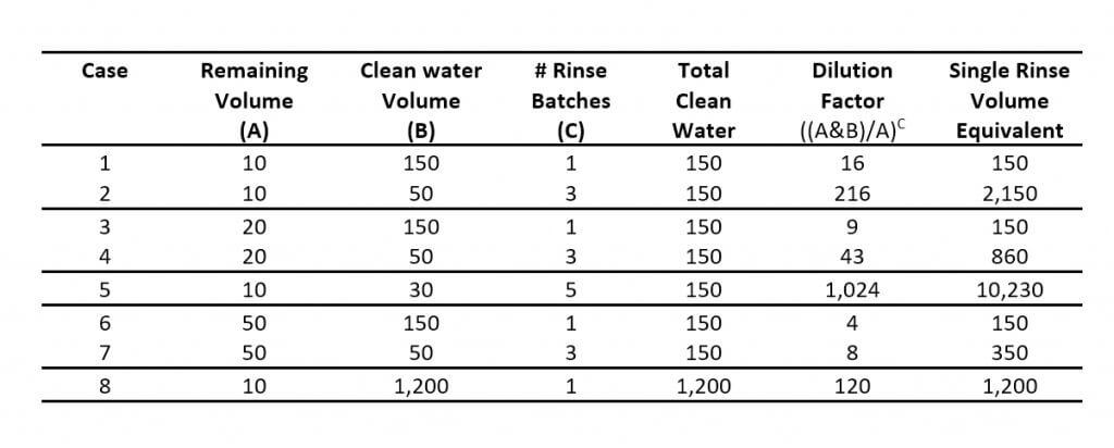
    The table below has some sample calculations. Note that the paired cases (1&2, 3&4, 6&7) all use the same total water volume, but compare a single vs triple rinse of three different remaining volumes.

    Comparing Case 1 to Case 3 or Case 6, (remaining volumes of 10, 20, and 50, respectively), it’s clear that minimizing the remaining volume is important.

    It’s also striking that the same amount of clean water, subdivided into three smaller repeat batches (Case 2, 4 and 7), is much more powerful than using single batches with the same total clean water amounts.

    Reducing the size of each batch even further and increasing the number of batches (Case 5) approaches what a properly executed continuous rinse can do.

    Is it necessary to dilute to the level that’s safe for the next crop? Not always. The next product in the tank acts to dilute the remainder once again, possibly by a factor of 100, depending on the remaining volume and the tank size (Case 8). The material in the boom, however, won’t be diluted by this additional volume, and therefore may harm the crop unless it is first sprayed out elsewhere, especially when section ends are not drained and rinsed.

    This is where a recirculating boom is valuable, providing an opportunity to charge the boom without spraying. The penalty is that the boom volume is then returned to the tank in the process, increasing the amount that needs to be diluted.

    Let’s return to the dicamba example with a 20,000-fold dilution requirement and a 1,200 gallon tank. We’ll consider two examples. In the first, the operator wants to prime the boom in the soybean field without any harm to the dicamba-susceptible beans. A 20,000-fold dilution is needed.

    We’ve looked at five options that each assume a remaining volume of 10 gallons. Note that our goal is the same – dilute by a factor of 20,000.

    The formulae:

    Dilution per Rinse = final dilution ^(1/# of rinses)

    Rinse Volume = (dilution per rinse * remaining volume) – remaining volume

    The maximum amount of dilution possible with a 1,200 gallon tank and a 10 gallon remainder is 120 (see Row 8, Table above).

    • One rinse diluting by 20,000 – impossible with a 1,200 gallon tank (max achievable is 120-fold);
    • Two sequential rinses each diluting by a factor of 20,000^(1/2) = 141. Also impossible with a 1,200 gallon tank;
    • Three sequential rinses, each diluting by a factor of 20,000^(1/3) = 27. A volume of 260 gallons can do this  (27*10)-10=260 gallons. For three rinses, the total volume is 780 gallons.
    • Four sequential rinses, each diluting by a factor of 20,000^(1/4) = 12. A volume of 110 gallons can do this, for a total volume of 440 gallons;
    • Five sequential rinses, each diluting by a factor of 20,000^(1/5) = 7. A volume of 60 gallons can do this, for a total volume of 300 gallons.

    The first two examples don’t work because the tank isn’t big enough. But the three remaining examples all work equally well, they just consume different amounts of clean water.

    If that doesn’t seem like a lot of work, then repeat this calculation with a 30 gallon remainder volume, common on many sprayers. Short on time? We did it for you here.

    Second, let’s assume the operator is prepared to prime the boom where it doesn’t harm soybeans. Now the first new product tank takes care of the last dilution, lowering the cleanout dilution requirement by 1,200/10 = a factor of 120. Now the cleanout dilution requirement is only 20,000/120 = 166.

    • One 1,200 gallon tank rinse can only achieve 120-fold dilution.
    • Two rinses, each diluting by 166^(1/2) = 13. Rinse volumes of 120 gallons are sufficient, for a total of 240 gallons.
    • Three sequential rinses, each diluting by a factor of 166^(1/3) = 6. A volume of 50 gallons can do this, for a total volume of 150 gallons.

    The math is simple, and can be done using the formula in the first table, or this app:

    The hard part is knowing what the remaining volume is. It would be very useful for a manufacturer to provide this information.

    In the meantime, you can estimate on your own. Add water with surfactant to your tank, and spray it empty. While spraying, turn the agitation on and off to fill and activate the sparge, if equipped. Once the tank is empty and the spray pressure drops, stop and drain the sump into pails. Ensure that the pump suction line and the pressure line up to and including the agitation and sparge lines also drain. Disconnect these if necessary. If there is a filter housing in this circuit, remove it as well.  Avoid collecting liquid from the pressure line beyond where the the agitation or sparge split off, as this will be pushed out to the boom.

    An alternative is to estimate the length of hose in this circuit, using the following table as a guide:

    And remember, diluting the remaining liquid is only one part of a cleaning process.

  • Application Recordkeeping: Focus on Environmental Conditions

    Application Recordkeeping: Focus on Environmental Conditions

    Note: This article was written by Bob Wolf of Wolf Consulting and Research, and first appeared as an NDSU Extension Service publication. Bob has agreed to reproduce the article on our website.

    When applying crop protection products, a good steward is one who can identify and record the environmental factors that may negatively impact making an application; particularly, the possibility of spray drift.

    New label language states: “Avoiding spray drift at the application site is the responsibility of the applicator.” A wise sprayer operator must possess the ability to assess the environmental conditions at the field location to determine how best to spray the field, or maybe decide it would be best not to spray that field, or part of that field, at that time. Instruments that assess environmental conditions are available to assist applicators in making good decisions.

    Making the correct measurement is the critical first step. Record the information measured to document the application conditions. Quality records help mitigate against any misapplication allegations, such as a drift complaint. Many of the items listed below are based on past legal experiences with applications involving spray drift litigation.

    The following guidelines should help you measure and accurately record environmental conditions at the application site.

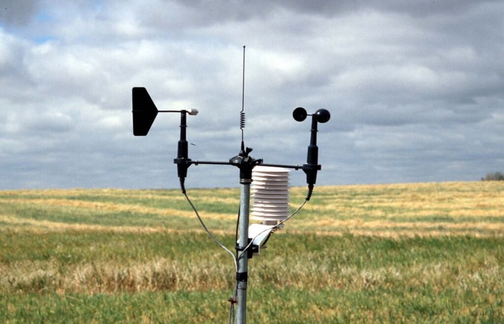
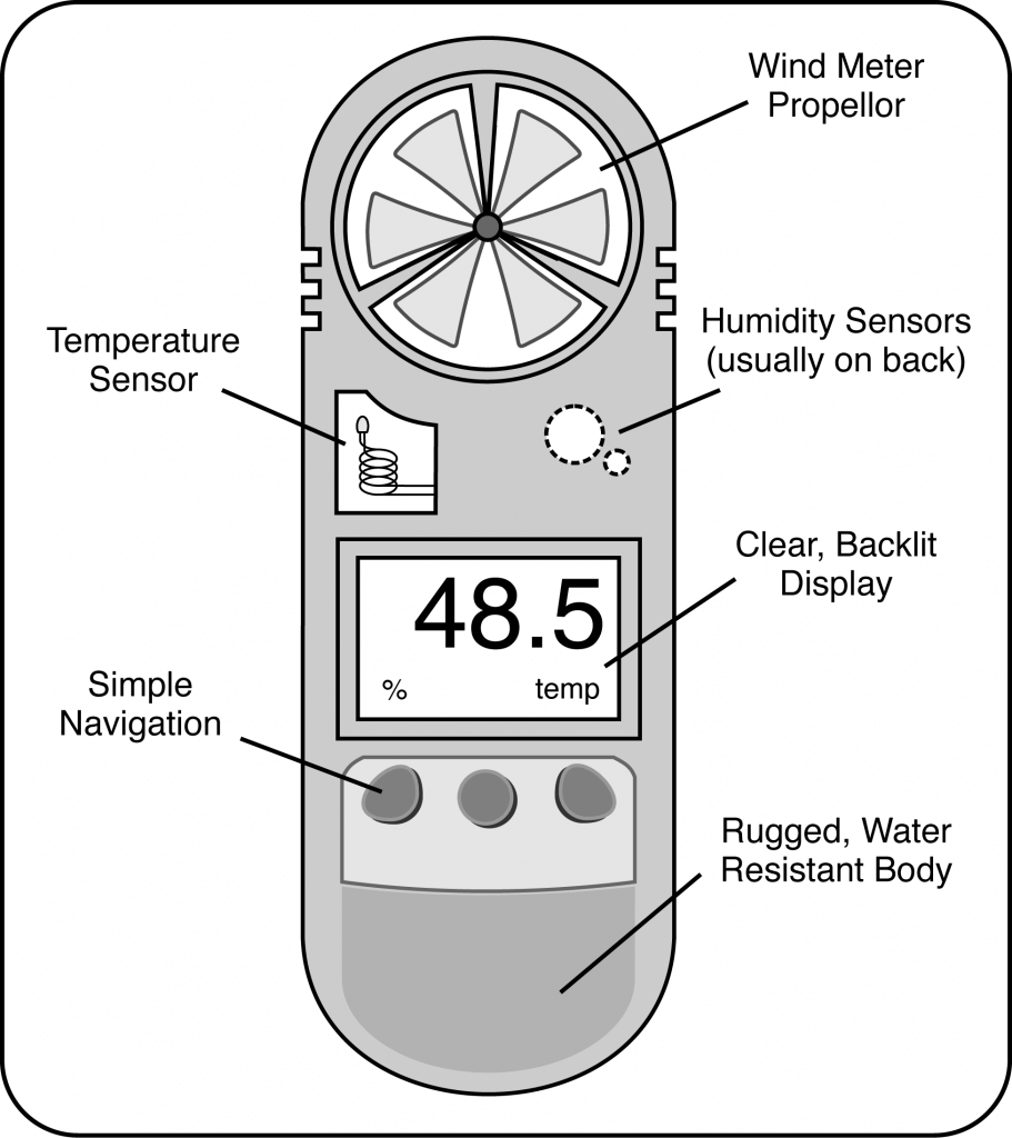
    1- Document any instrument used by recording the manufacturer and model number. Accurate portable weather instruments are recommended. Portable weather instruments are available that log and store data, and aid in auditing and recordkeeping. Some will have Bluetooth/wireless capabilities.

    2- Environmental measurements include wind speed and direction, temperature, and relative humidity.

    3- At a minimum, record data at the start and finish of the job. Consider more often as conditions change or for a job that lasts over a longer period. For example, make observations when tank refilling for larger fields. Time stamp all observations with a.m., p.m., or military time.

    4- Take meteorological readings as close to the application site as possible. Be advised that the weather data received via a smart phone or local weather station may not be accurate for the location being sprayed.

    Note the specific location where the measurement was made, such as GPS coordinates, field entry point, field location, etc. Check the label to see if it requires a specific observation location in relation to the treatment area.

    5- Make all measurements as close as possible to the nozzle release height (boom height) and in an area not protected from the wind by the spray machine or your body. For aerial applications, six feet is suggested when using a hand held instrument.

    6- Record wind speed averaged over a 1 to 2 minute time span. Note the time the observation was recorded. Most instruments give an average over a period of time. Make sure the instrument’s anemometer is facing directly into the wind.

    Do not record winds as variable or with a range i.e. 4 to 8 mph – an average gives a better indication of the transport energy. Light and variable winds, where directions may change several times over a short period, can be more problematic than higher speed winds in a sustained direction. Observe any label restrictions on wind speed.

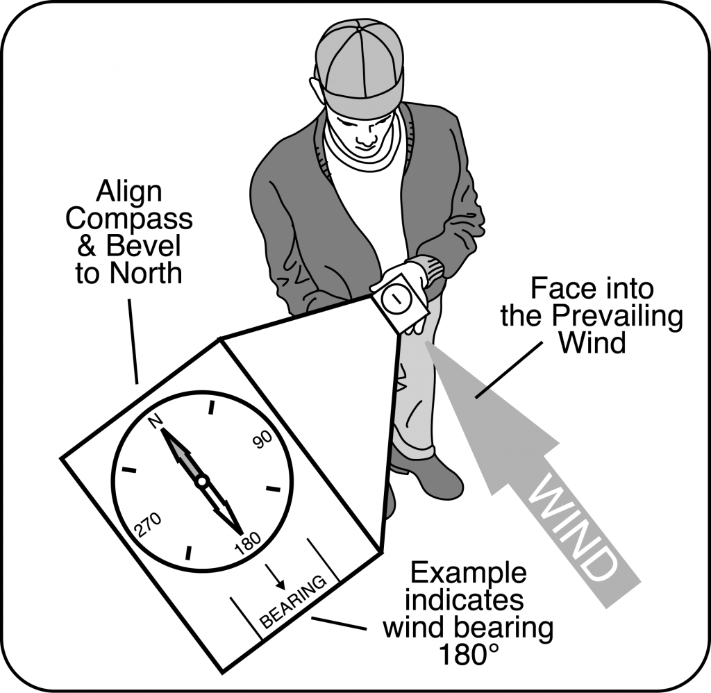
    Wind direction requires a similar averaged measurement. Record direction in degrees magnetic from a compass (0-360°). The use of alphabetic characters, i.e., N, S, NW, to indicate wind direction is discouraged. The key for determining direction is to have an accurate assessment method: trees moving, dust, smoke, a ribbon on a short stake, etc. Face directly into the wind and record the direction from which the wind is coming. A ribbon on a stake with the ribbon blowing directly at your body is a simple fail safe approach. Movement of smoke, particularly from moving aircraft, or dust may help determine direction.

    7- Record temperature and humidity since they can be helpful in determining temperature inversion potential. It may be advisable to record both temperature and humidity well before and after the application for this purpose. In fact, recording a morning low and an afternoon high would be useful regarding determining the potential for an inversion. Take temperature measurements with the instrument out of direct sunlight. Shade the instrument with your body or spray equipment. This is especially critical if you are trying to assess temperature differentials for determining if an inversion is in place.

    8- Be alert to field level temperature inversion conditions which typically occur from late afternoon, can be sustained through the night, and into the next morning. Beware, inversions can start mid-afternoon. Observe conditions such as the presence of ground fog, smoke layers hanging parallel to the ground, dust hanging over the field/gravel road, heavy dew, frost, or intense odors (i.e., smells from manure or stagnant water from ponds are held close to the surface when inversion conditions exist). Inversions commonly occur with low (less than 3 mph) to no wind speeds. Spraying in calm air is not advised. If a mechanical smoker is used note wind direction and smoke dissipation with a time stamp.

    9- Note any variances due to terrain or vegetation differences, tree lines, buildings, etc.

    10- Initial or sign all recordings to indicate who made the observation(s).

  • The Misplay of our Generation

    The Misplay of our Generation

    We tend to overestimate the effect of a technology in the short run and underestimate the effect in the long run.

    –Amara’s Law of Computing

    We tend to overestimate the effect of a stewardship mistake in the short run and underestimate the effect in the long run.

    –Wolf’s Adaptation of Amara’s Law to Agricultural Stewardship

    August 9, 2017

    Since June of 2017, we’ve been hearing reports of widespread dicamba damage symptoms in soybeans throughout the US mid-south and midwest. It appears that millions of acres could ultimately be affected, and yield impacts are unknown at this time.

    For those new to the issue, dicamba is a broadleaf herbicide in the Group 4 mode of action group, a benzoic acid. It’s an important tool for herbicide resistance management for weeds like palmer amaranth (Amaranthus palmeri) and waterhemp (A. tuberculatus), populations of which have become resistant to Group 2 (ALS inhibitors), Group 5 (triazines), Group 9 (glyphosate), Group 14 (PPO inhibitors) and Group 27 (HPPD inhibitors) in some places.

    Dicamba is a volatile herbicide, discovered in 1942 and first registered in the US in 1967. Its primary use was in corn and other cereal crops, lawns, and rights of way, at comparatively low doses, and relatively early in the season.

    Calling a pesticide volatile means it can evaporate after application, either from a liquid or a dry deposit, for hours or sometimes days after application. The resulting vapor cloud can move unpredictably, depending on atmospheric conditions, and affect plants long distances away. Higher temperatures increase vapor loss.

    Starting this year, dicamba-tolerant soybeans and cotton (Xtend varieties) were sprayed with new lower-volatility formulations of dicamba, XtendiMax, Engenia, and FeXapan, to control certain broadleaf weeds (including the Amaranth species above) without harming the soybeans. Problem is, dicamba can harm non-Xtend soybeans and other plants, even at very low doses. And these registrations were for applications that occurred later in the season, at higher doses than before.

    I usually don’t get involved in people’s decision about whether to spray, or what to spray. But I do get involved when it comes down to how to spray. That’s my job. The real question to me is “can this product be used safely in cotton and soybeans?” Right now, the jury’s out on that one.

    In my business, our guiding principles are what some people have called the “Three Es of Application”, Efficacy, Efficiency, & Environment.

    We use sprays to control pests. That’s the only reason. We have to apply them so that they work, or else it’s a wasted effort. That’s the efficacy part. We also need to use our resources, time, money, etc., efficiently so the whole process doesn’t bankrupt us and we have time left for other important tasks.  That’s efficiency. And finally, we need to protect the environment, and that means making sure the product lands where it’s intended.

    None of these three priorities trumps the others. All need to be met to the best degree possible. And due to ever-changing conditions, we will typically change our approach to emphasize one or two of these three over the others, to have a working system.

    Simply put, pesticides belong on target surfaces covered by the swath of the sprayer, and nowhere else. If they do move elsewhere (something we’ve come to view as inevitable), regulators conduct risk assessments to ensure that this movement does not result in harm. If harm is possible, mitigating tools such as application timing, product rate, spray method, and buffer zones may be imposed. If those tools aren’t enough to ensure safety, regulators deny product registration. That’s their job.

    But even if no harm is done by trespass, the products still need to be on-target. That’s stewardship. It’s a principle whose adherence gives license for a technology to be used. It gives others faith in our competence. Practicing this principle when it’s easy prepares us for hard times.

    I respect our regulatory process, and know it to be increasingly conservative with regards to risk the less data there are. I worked for the PMRA (the Canadian pesticide regulatory agency) as an application expert for five years. I know the system isn’t perfect and can make mistakes.  I know the system can be political. Usually it’s by being too careful. With dicamba, it looks like the opposite happened.

    The reason we’re seeing dicamba leaf cupping everywhere isn’t because all applicators suddenly forgot how to spray. They didn’t suddenly get reckless. They didn’t wilfully ignore all the training that the dicamba manufacturers and state and provincial governments developed in preparation for the product launch.

    Instead, dicamba drift reports arose from a combination of extreme sensitivity and easily identified symptoms, as well as an unexpected (by some) amount of vapor drift. Even good applications appeared to create problems. Despite warnings from local experts, regulators and registrants didn’t see it coming.

    Experienced agronomists have suggested that the observed dicamba trespass of 2017 implicates both temperature inversions and vapor drift. And although the new product labels advise against spraying under inversion conditions, they don’t say a word about vapor drift, the conditions that give rise to it, or how to protect against its occurrence. Not one word. I’ve searched the XtendimaxEngenia and FeXapan labels. Nada.

    Seems that the regulators and registrants felt confident enough in the reduced volatility of dicamba, based on their internal empirical data and modeling, that they didn’t need to mention it on the label. Calling that a mistake is an understatement.

    I’d call it the biggest spray application misplay I’ve ever seen.

    A part of the problem may be the enormous scale on which this new use of dicamba was introduced, over 25 million acres of Xtend crops. Scale-up errors are common in many industries. Emergent properties related to scale can’t readily be predicted by empirical data and models. Especially when the underlying data are scant.

    So what to do? The continued success of agriculture depends to continued access to safe crop production tools. Irresponsible use threatens that. And by irresponsible use, I don’t just mean application. I also mean registration, promotion, sale, and support. The whole stewardship package.

    When problems occur, we need to be quick on our feet to acknowledge them, to support those affected, and to try to understand the cause and prevent the situation from continuing or getting worse.

    The current industry response appears to be the exact opposite. What I’ve seen is full of denial, downplaying, innuendo, blaming, and entrenchment.

    Why is such an important issue in pesticide stewardship handled so poorly?

    The immediate victims of this situation are the producers that depend on new technologies. But the long-term victim is agriculture as a whole. The lack of humility and leadership by many of the proponents of this technology, those with no small financial stake in its continued use, hurts not just them, but all of us involved in farming. This is not stewardship. It’s not license. It’s short sighted and reckless.

    Over my career, spray application has generally become safer for the operator and the environment. A big part of our success has been the adoption of low-drift nozzles, the de-facto standard for modern pesticide application. The development of less toxic and less persistent pesticides has also been very important. We can avoid a lot of problems with good chemistry. I’ve been proud to tell this story.

    I want to stay proud of our story. And in this case, that requires admitting to mistakes that were made and taking corrective action that is in the best interest of our entire industry. Agriculture will persist longer than company brands and titles. It takes priority.

    It’s still too early to fully understand all the reasons for the widespread dicamba damage. But it’s not too soon to say that much of this could have been prevented with a smaller rollout, with greater collaboration with government and university experts during registration, and with more honest information on dicamba volatility on product labels. Call it Volatility Humility.

    We’ll all pay for the mistakes that were made. We’ll likely have more stringent and expensive registration protocols. More restrictive application parameters. Strained relationships. More distrust of agriculture.

    And as always, an ounce of sweet prevention would have been much better than the pounds of bitter cure that will surely be required to make this right.

  • Plumbing Projects That Make Spraying Easier and Safer

    Plumbing Projects That Make Spraying Easier and Safer

    Some of our biggest struggles in spraying involve the start and end of each spray day.

    When starting a new field after the sprayer is cleaned, we need to prime the boom. If it’s full of water, that water has to be purged and the question is always for how long and where to do this (pro tip at bottom of article).

    At the end of the day, we should ideally clean the sprayer. During that process, we may struggle with waste disposal, including large rinsate amounts, and course, the uncertainty of whether the job is actually done (since clean water looks exactly the same as contaminated water).

    If not cleaning the entire sprayer plumbing, we should at least rinse the boom, even if we’re returning to the same product the following day. It can prevent future problems.

    These tasks are complicated by the increasingly convoluted plumbing featured on modern sprayers. Ask someone to explain their sprayer’s plumbing system to you one day. It’s a long story! A bright spot is the well-engineered, compact, and accessible Agrifac system.

    Fortunately, virtually any sprayer can be modified to suit your needs. Let’s talk about a few ideas for a winter project:

    1. Boom flush. It’s good practice to flush clean water through your boom at the end of spraying even if the main tank remains full of product. Some sprayers have an air purge system to eliminate liquid from the plumbing and that is a great feature. A water flush should follow that purge so that any residual pesticide is diluted and removed before it can dry on and become hard to remove later.  First you’ll need a clean water tank on the sprayer (150 gal is enough). Second, plumb a feed so that this clean tank can be the sole source of the water supplied to the solution pump. Select this source, shut return lines down or off, and pump clean water through boom.  Sprayers that have an auto-rinse cycle will likely be able to draw clean water, but may not be able to push it to the boom, directing it to the wash-down nozzles instead. Check to see what’s possible, and make the changes you need.
    2. Clean water pump. Installing a second pump dedicated to the clean water tank has several advantages. We’ve talked about continuous rinsing before, here, and here, as a way to dilute the tank remainder faster. It requires installation of a second pump dedicated to clean water. Additionally, give this pump the option to deliver water to the boom, not just the wash-down nozzles. Now it can be used to rinse water through the boom. The main challenge is to obtain a pump capacity that can match the needs of the boom and/or the wash-down nozzles.
    3. Boom ends. We’ve mentioned this part of the boom many times. Boom ends must be flushed regularly to get rid of product and possibly debris that gets stuck there. A simple way to achieve this is to use the Express Nozzle Body End Caps from Hypro. These bleed air continuously, and also prevent accumulation of dead-end contamination. They do need to be flushed, and this can be done by pulling a plug or rotating the turret to an open (no nozzle ) position.
    1. Recirculating boom. This is a significant change, but worth considering. Conventional plumbed booms are separated into five to 13 sections. Each has two ends at which the spray stops and where air and contamination can accumulate (see point #3). Each section feed has a shutoff valve.  Once the spray mixture leaves the pump and bypass valve, it is committed to leaving the sprayer.  In a recirculating boom, the boom becomes a part of the tank and the liquid can return to the tank if desired. Spray is pressurized at one or both ends, and valve positions determine its flow. Sectional control is achieved with individual nozzle shutoff, air or electric.
      1. Three advantages:
        (a) the boom can be primed with new product without spraying. The surplus goes back to the tank.
        (b) the boom can be flushed with water without spraying while material is still in tank, and without spilling anything on the ground. Again, the surplus goes back to the tank.
        (c)  high resolution sectional control with individual nozzle shutoff is a byproduct of this design. Fast response, high res, saves money.
    2. Steel lines. Steel cleans easier than plastic, and this material makes a lot of sense for booms. But it also makes sense for the boom feeds, currently handled by black rubber hose.  This hose is a literal black box. We can’t see inside it, and we don’t know if and where potential contamination resides. It has considerable surface area. Consider replacing portions of your feed lines with steel. The boom is the obvious candidate. Aside from easier cleanout, it also helps with faster nozzle shutoff because it doesn’t expand with pressure.

    A word about dumping the tank on the ground. It’s a bad practice for many reasons. Let’s examine just one of those. When you spray a product at 10 gpa, you actually cover each square meter with about 10 mL, or 1/3 oz, of spray mix. When you flush your boom ends on the ground, you’re probably dropping 2 or 3 gallons in the same area. That’s 1000 times the label rate at each boom end, 10 to 26 times per boom. If you dump your tank remainder and all the hoses, say 20 or 30 gallons, that’s 10,000 times the label rate if it covers 1 sq meter. That’s leaching, runoff, residual potential, and not a good story.

    Many of the changes we outlined above help prevent that from being necessary.

    Pro Tip: To find out how much water your plumbing (from the pump to the boom ends) holds, do this: After cleaning with water and before spraying an EC formulation (white milky appearance in tank, some crop oils are ECs) reset your sprayed gallons on your rate controller. Start spraying and watch for the last nozzle on your furthest and longest section to spray white. Stop spraying and check your sprayed gallons. That’s your volume. No matter the size of nozzle or application volume, it stays constant. To be sure the boom is primed with a new mix, spray until those gallons are reached and you’re set.