PWM is gaining popularity, and there is an ever-increasing number of first-time users that need to make nozzle selections for their system. We’ve written about it here, here, and here.
Recall the PWM replaces spray pressure with Duty Cycle (DC) of a pulsing solenoid as the primary means of controlling nozzle flow. The solenoid shuts off the flow to the nozzle intermittently, between 10 and 100 times per second depending on the system. The Duty Cycle is defined as the proportion of time that the solenoid is open, and for low-frequency systems, DC is more or less linearly related to flow rate.
The first rule of PWM nozzle selection is to understand that under average travel speeds, we’d like to see the duty cycle of the system at between 60 and 80%. This means that the nozzle solenoid is open about 2/3 of the time. This value also describes the flow rate as a proportion of the full capacity that nozzle.
The reason for this 2/3 duty cycle rule is to enable four key features of PWM:
It’s ideal for turn compensation, allowing the outer nozzles to increase their flow 20 to 40%, and the inner nozzles to decrease flow about three-fold, in accordance with boom speed.
It allows speed flexibility, providing some additional speed, but more importantly, reduced speeds should conditions require it, without a change in spray pressure.
It compensates for pressure changes so that spray quality can be adjusted without requiring a speed change. Less pressure reduces nozzle flow, and increasing DC recoups accordingly.
It allows for customized higher flows of certain nozzles, perhaps behind wheels, to address reduced deposition in their aerodynamic wake (available on some PWM systems).
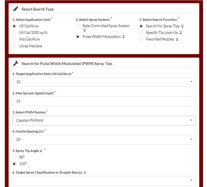
The best tool for selecting the right nozzle size is Wilger’s Tip Wizard. This site asks for your desired average speed ( although it calls this “Max Sprayer Speed”), and reports the expected DC for a host of nozzle size solutions and pressures. It also reports maximum and minimum travel speeds and other useful information such as spray quality.
Fig 1: The Tip Wizard is a useful tool for sizing nozzles on any PWM system. Sizing information applies to any nozzle. Spray quality information is for Wilger ComboJet nozzles only.
Although intended for Wilger nozzles, the site’s sizing feature works for any nozzle brand. It asks the user which PWM system they have for the purpose of calculating the documented pressure drop across the solenoid.
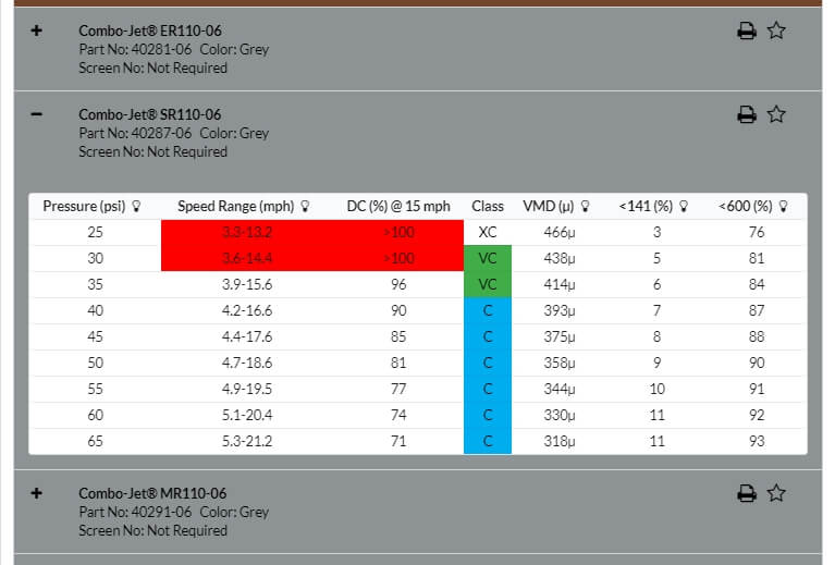
Fig 2: Tip Wizard results for the Wilger SR11006 tip at 10 gpa and 15 mph. Look for a solution that provides 60 to 80% Duty Cycle (DC).
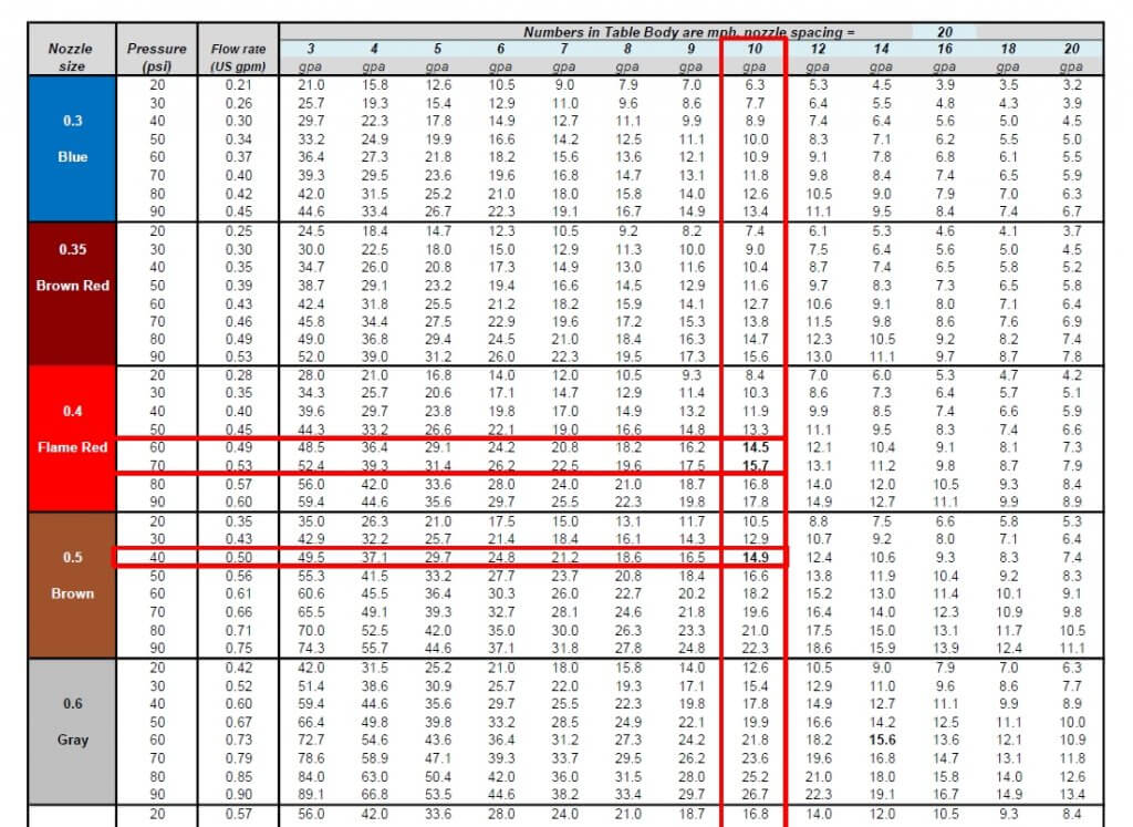
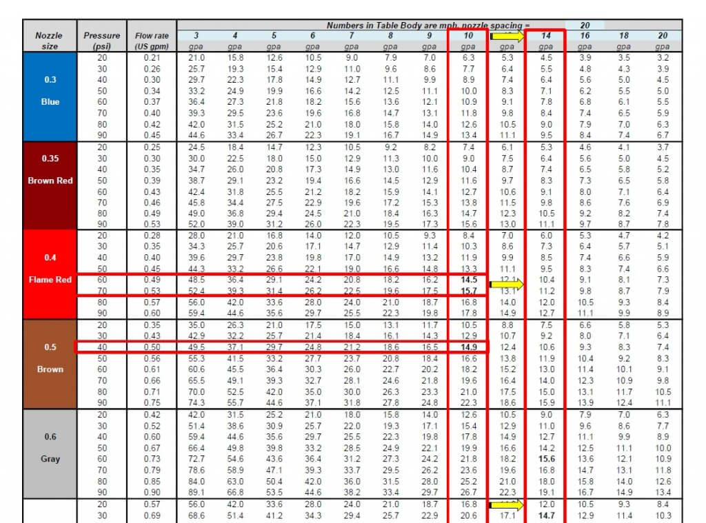
If you don’t have access to the site, a basic calibration chart can still work with a simple trick. Recall that we use the top row to identify the desired water volume, and the table’s interior values are speeds, as described here.
Below are two solutions for someone wanting to apply 10 gpa at 15 mph without PWM. The correct choice depends on the required pressure to produce the needed spray quality.
Fig 3: A conventional calibration chart, solving a 10 gpa application for 15 mph.
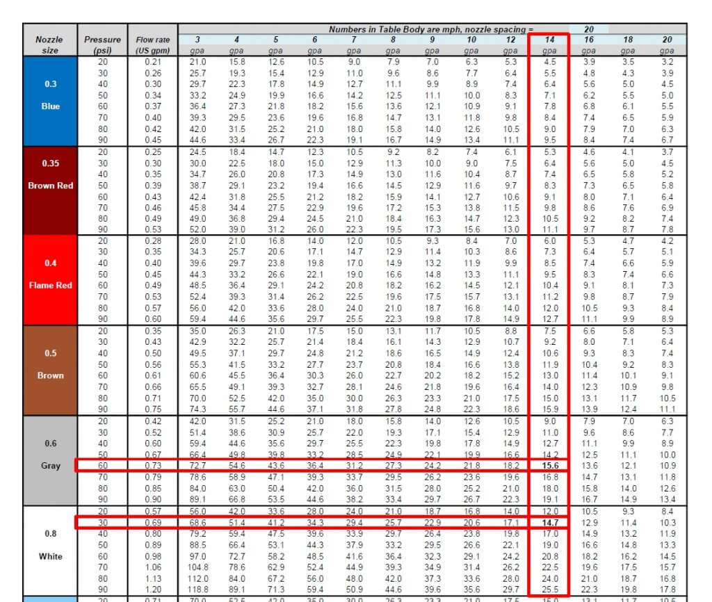
If you want to apply the same 10 US gpa using PWM, simply solve for a larger volume that offers the right DC. For example, choosing 13 gpa will over-apply by 3 gpa, or 30%. The PWM system adjusts by running at 100-30=70% DC. If the chart doesn’t offer 13 gpa, go nearby, to 14 gpa, as we did below:
Fig 4: By pretending to require 14 gpa instead of the actual 10 gpa, the conventional calibration chart is tricked into solving for a nozzle size that will work with PWM at 60% Duty Cycle.
Now solve for the same target speed, 15 mph. The solution will run at 60% DC. Again, there is more than one choice, and that will depend on the spray pressure needed.
Fig 5: Two possible solutions for achieving 10 gpa at 10 mph. An 06 nozzle at intermediate pressure or an 08 nozzle at low pressure.
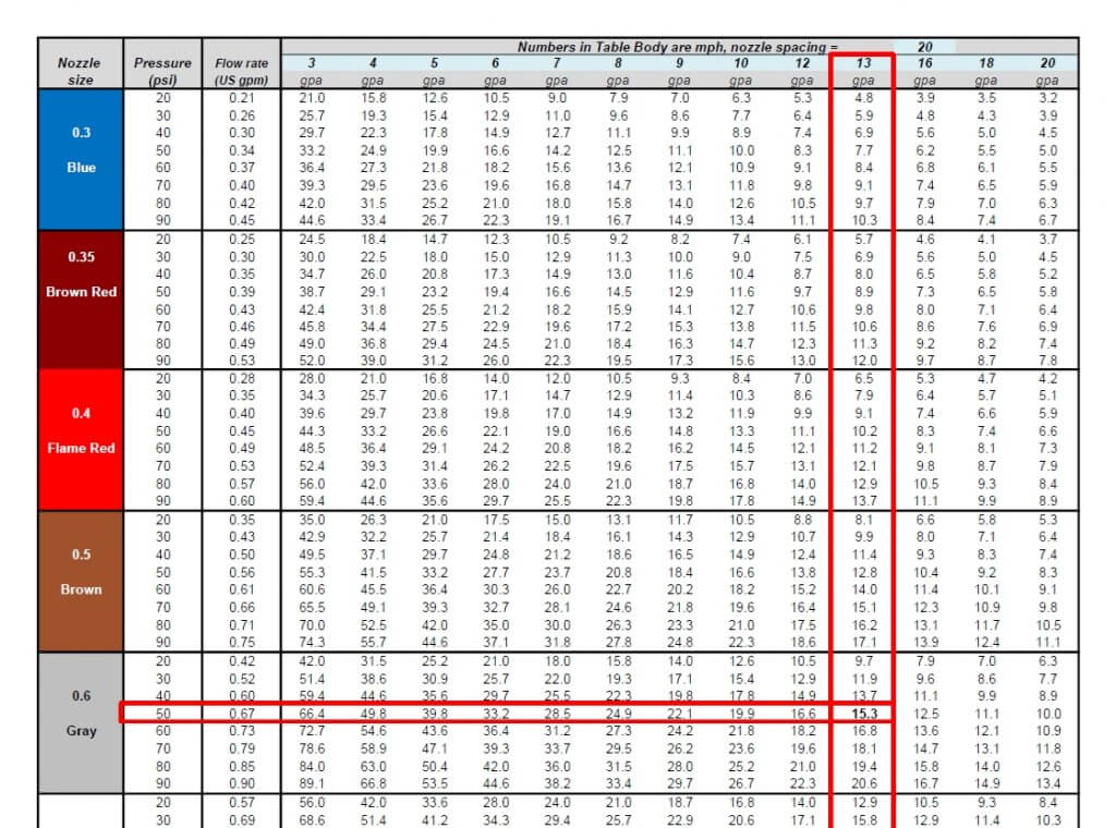
We’ve developed a template, in US or metric units, that can be customized for any water volume. Here is the same chart with 13 gpa added:
Fig 6: A conventional calibration chart with the 13 mph speed added.
The best solution for 10 gpa at 15 mph is the 06 size nozzle at 50 psi. This is not engraved in stone. One of the nice things about PWM is that it has inherent flexibility. Make the nozzle pressure a priority to get the correct spray quality. It really doesn’t matter whether the resulting DC is 65 or 80%, the system will still work well. Simply avoid extremes that take you below 50% or above 90%, they will limit the system’s capabilities.
It can handle any water volume or nozzle spacing by filling in the blue cells. Two additional worksheets in the file automate the process, simply enter the desired application volume, travel speed, and nozzle spacing (yellow cells), and the solution that offers the optimal duty cycle range will be highlighted in light green.
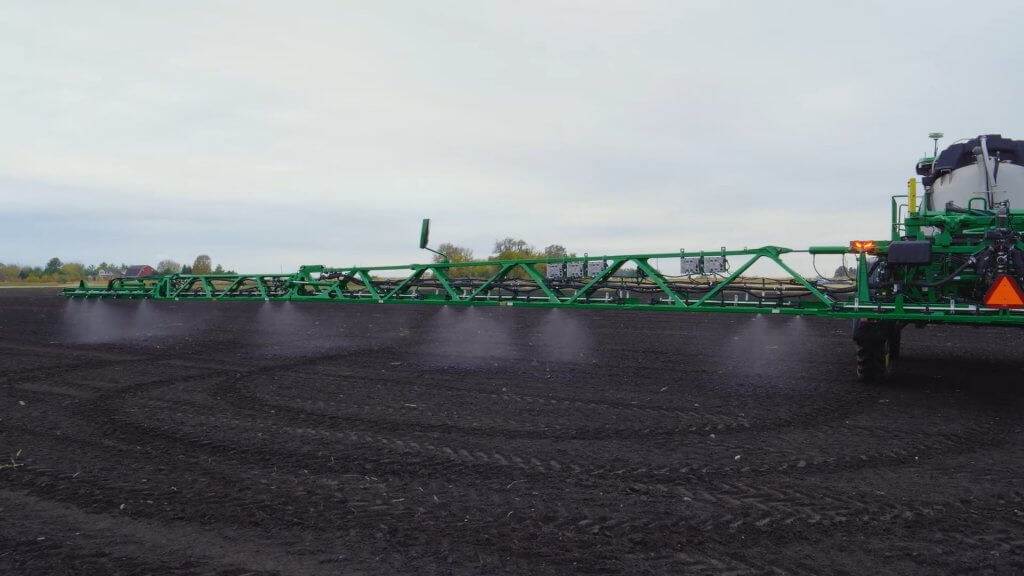
On March 2, 2021, John Deere entered the optical spot spray (OSS) market with its first product, See & Spray Select™. This “Green on Brown” system identifies green material on a non-green background and is thus suited for pre-seed burnoff, chem fallow, or post harvest. It is competing for the same market space as Cropland’s WEEDit and Trimble’s WeedSeeker, but uses a slightly different approach.
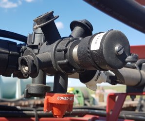
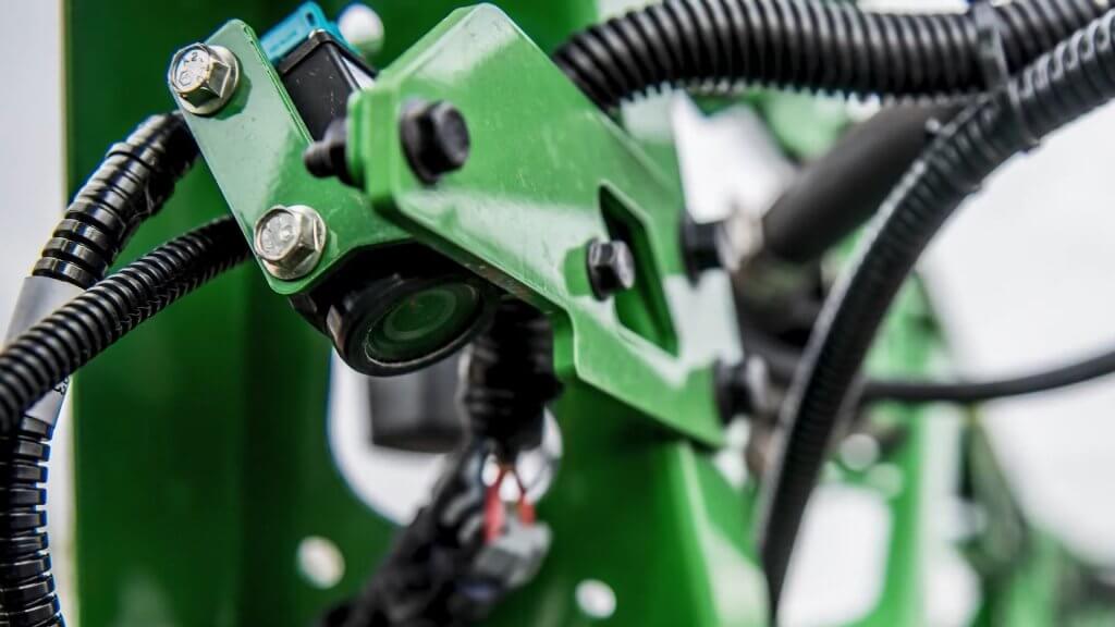
At the heart of the See & Spray system is a relatively simple RGB camera that is mounted directly to the boom and looks about 1.5 m ahead. When this camera detects a spot of green colour, it assumes that this is a plant and activates a nozzle in line with that plant. John Deere says the weed size threshold is about ¼” (6 mm), and is evaluating its experimental data to identify exceptions to that rule of thumb.
See & Spray Select uses an RGB camera to detect weeds (Image courtesy John Deere)
In 2017, John Deere conducted a highly publicized acquisition of Blue River Technologies, a start up that pioneered artificial intelligence (AI) plant identification and coined the term “See & Spray”. However, the technology John Deere announced this time originated with the University of Southern Queensland near Toowoomba, Australia. The university’s Centre for Agricultural Engineering had received some initial seed financing from Sugar Research Australia, Cotton Research and Development Corporation, and Hort Innovation, and eventually partnered with John Deere. This is yet another example of the value of farmer investments in research.
Blue River contributed to this project but remains committed to its path of developing Green on Green OSS through machine learning. John Deere says this first product is part of an evolution of spraying with ever-increasing precision that will culminate in spot spraying weeds within a canopy.
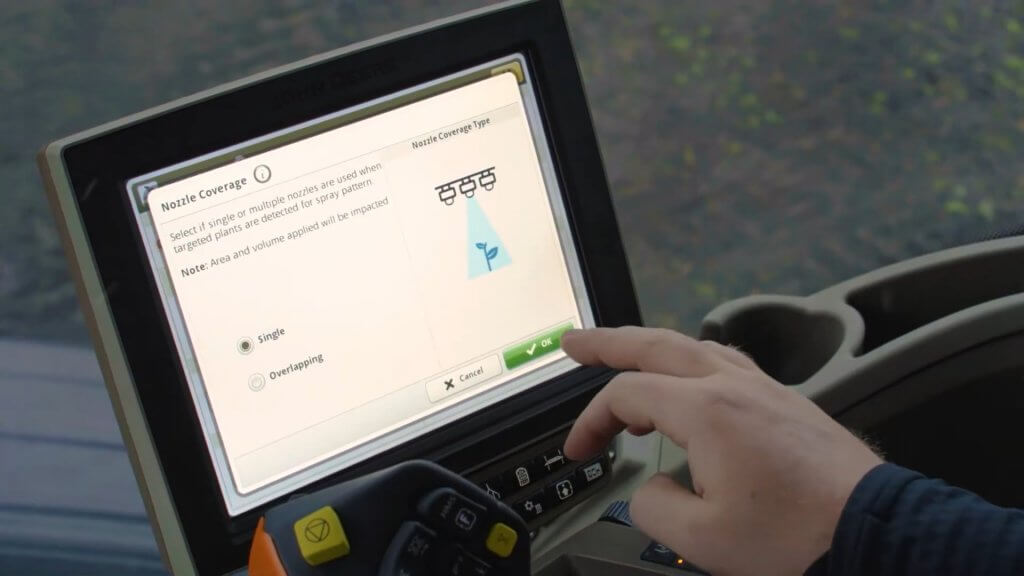
The pixels in the See & Spray camera chip are mapped during its initial calibration, allowing the processor to know which nozzle to turn on. There are two user-selected modes. In “Single Nozzle” Mode, the system turns on as few nozzles as possible. If the weed is directly under a nozzle, just that nozzle is turned on. Should the weed be in between two nozzles, both will be turned on. In “Overlapping” Mode, a detection will turn on at least three, and up to six adjacent nozzles. This mode is intended for herbicides that contain specific nozzle recommendations on the label, such as dicamba. By fitting these tips on the spot spray location, the required overlap and subsequent coverage can be guaranteed to be compliant with that label, a unique feature of See & Spray.
The number of nozzles activated by a weed detection depends on the location of the weed relative to the nozzles, and the mode selected by the user (Image courtesy John Deere)
In all modes, the user can specify the distance before and after the detected plant that the nozzle will spray. This feature is useful when boom height varies or when travelling faster to provide extra assurance that the target will be covered by the spray. The boom height range for See & Spray is 26 to 47” (66 to 120 cm), and the maximum travel speed with nozzles pointed down is 12 mph.
Installation of a 40 degree angled adaptor allows sprays tom be emitted backwards, and increases the spray speeds to 16 mph due to the extra distance and time afforded the sensors andoin processors to make a decision.
See & Spray has a built in contingency for suboptimal conditions, for example when the boom falls outside its height range, or the nozzle speed (not tractor) exceeds the 12 or 16 mph maximum in a turn, or a light or sensor or processor fault occurs. Called “Fallback Mode”, the boom can be configured to shut off, or to go into broadcast mode (using the spot spray nozzles) at that time. These types of insurance are a necessary part of an OSS on the market today.
To prevent fallback mode from occuring unecessarily, operators often choose to reduce their tractor speed one or two mph to allow for yaw without triggering all the nozzles.
No OSS system is perfect. Tiny weeds, or those obscured from camera view by crop residue, may be missed. The contingency for WEEDit is “Combined Mode”, where the entire boom emits a broadcast spray at a user-determined fraction of the full dose, while still maintaining spot spray capability at the full dose when a detection occurs. The reduced dose is sufficient to control the smallest weeds, whereas the spot spray is emitted at the full label rate for the larger ones. This capability is made possible through Pulse-Width Modulation (PWM) control of each nozzle.
John Deere has developed a mode of its ExactApply system to create the same outcome. Called “A & B Mode”, the rear nozzle (B location on the ExactApply nozzle body) is being activated by See & Spray. The front nozzle (A location) can be asked to spray simultaneously over the entire boom width. By choosing a smaller nozzle, a fraction of the label rate can be applied as a broadcast while maintaining spot spray capability. The broadcast boom is pulse-width modulated and retains the swath control and turn compensation of ExactApply. This mode also makes it easier to ensure coverage of these smaller weeds by selecting a finer, wider (110 degree) angles spray on the broadcast boom, and retaining a coarser, narrower fan angle banding nozzle for the spot application. The spot spray does not use PWM, relying on conventional speed and pressure to ensure the correct rate.
If planning to use A & B Mode, a user would first need to decide if they will calculate the spot spray dosing on a single or a multiple activated nozzle system. If priorizing the single nozzle actiation, one would first determine the band width of that nozzle, and size the nozzle accordingly. The band width should be ar close to the nozzle spacing as possible to maximize savings. Say the sprayer has 15″ spacing, and the nozzle’s band width is 20″. Now, whenever multiple nozzles are activated, they would operate as a 15″ spacing and would over-apply 20/15 = 1.33, or 33%. Say you want to apply 15 gpa (you may need to boost the spot spray volume to allow you to cut that with the broadcast feature). You can do it with the band (and overdose when using multiple nozzles, or apply 15 gpa with the multiple nozzles, underdosing by 28% when a single nozzle is activated. Or split the difference.
The next step is to select the application rate of the broadcast. If you want to apply 30% of the spot spray rate using the broadcast nozzles, size these accrodingly to apply 5 gpa.
For band- and spot-sprays, the width of the spray pattern at the target height determines the dose, therefore careful selection is advised. A worksheet that shows boom heights at various fan angles and nozzle spacings is downloadable here. TeeJet and Hypro offer a selection of narrower flat fan tips, but none yet in a low-drift design. Other nozzles are in development. Agrotop has already developed a low-drift “Spot Fan”, and MagnoJet, a Brazilian ceramic nozzle supplier, has 30 and 40 degree low drift tips for sale. Wilger has develped the DX series ComboJet tips in 20, 40, and 60 degree fan angles, in a low drift (pre-orifice design that works with PWM.
The camera sensing threshold can be adjusted to optimize a specific target. For example, to specify a certain weed size, that weed can be held in view of the sensor and the user can adjust the sensitivity until the weed is properly detected. As with any higher sensitivity, this runs the risk of more false detections, resulting in over-application. But it gives the user some knowledge that an important weed stage is being targeted properly.
The See & Spray camera relies on ambient light conditions, and John Deere recommends it not be used within 30 minutes of dawn or dusk. Both WEEDit and WeedSeeker, in contrast, can operate under any light conditions.
One of the challenges of running a OSS boom is the unpredictable fluctuation in flow requirement, which can theoretically range from just a few nozzles spraying to the whole boom activated in less than one second. While this extreme example is rare, a sophisticated and fast-responding pressure-based flow capability is nonetheless required. WEEDit uses a Ramsay Valve into their units to handle this challenge, whereas John Deere is relying on its existing plumbing design.
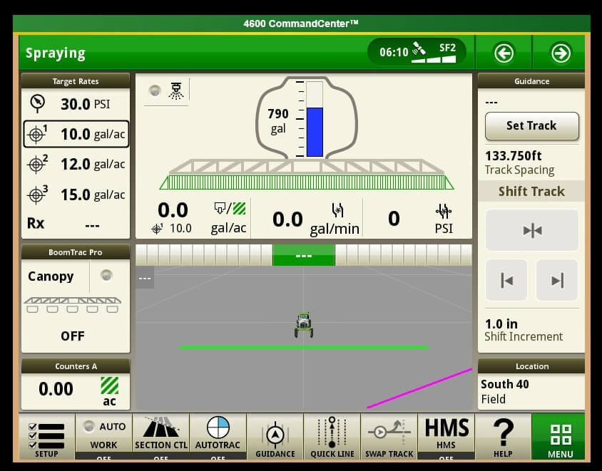
As a factory install, the See & Spray is fully integrated into the Series 4 display and is tied into JD Link. As a result, it can generate a high resolution map that shows each spot spray activation, by nozzle. The agronomic utility of this capability is significant, as it provides a very high resolution plant density map. This capability is also inherent in WEEDit and most green on Green systems available..
See & Spray Select is a factory option and comes integrated into the 4600 series monitor (Image courtesy John Deere)
It’s no secret that I believe optical spot sprays represent the future of pesticide application (see here). And it’s great news to see John Deere enter the OSS area with a factory installed option. As an influential force in ag, it lends credence to the concept and will benefit all other companies vying for this space. As they say, a rising tide raises all ships.
The John Deere ExactApply system has a pulsing feature, more commonly known as “Pulse Width Modulation” (PWM). From the operator’s perspective, it’s important to know the Duty Cycle that the system is operating at. The Duty Cycle (DC) is the percentage of time that the pulsing solenoids are “on”, or flowing. At the average travel speed, the pulsing system should operate at 60 to 80% DC for optimum performance. For in-depth explanation of ExactApply, read here.
Unlike its PWM counterparts (Raven Hawkeye, Capstan Pinpoint), the new John Deere 4600 monitor does not display the DC by default. Fortunately, it offers a module for insertion to its run pages.
The module isn’t perfect, and inserting it into an active run page is torture.
Here is how to bring this module onto a 4600 screen:
1. On 4600 Monitor, click on “menu” (bottom right).
2. Select “Applications” tab.
3. Choose “Layout Manager”.
4. Edit Run Page Set.
5. It’s easiest to copy an existing Run Page, rename it, and then customize its modules.
6. Make room on new Run page for new module. On my copy of the “Spraying” run page, I’ve deleted a module on the bottom left that I have elsewhere. Now “Add Module”.
7. Select “Machine Settings” tab, then “Boom & Nozzles”.
8. Scroll down to “Section Flow %” (four windows) and “Add Module”.
9. Module is placed in available open area. There is a warning if not enough screen space is available.
10. Save new Run page. Make sure it’s part of the “Active Run Page Set” in Layout Manager so it’s available to scroll to while spraying.
The module is a bar graph that gives you relative DCs along boom. In the first example, we’re driving straight and everything is fine. After a couple of shoulder checks, we pull out the smartphone and take a picture.
The bar graph format is useful during turn (left in this example, forcing higher DC to outside of boom, the right).
If it plateaus on outside (as in tight right turn, below), you are under-applying on the outside since the DC can’t go higher than 100%. Slow down and that improves it because it lowers the duty cycle of the entire machine.
Slowing down may cause too low a DC, resulting in over-application on inside of boom because the DC can’t be reduced below 15%.
Remember, for Turn Compensation to work, make sure the box is checked (Menu|Boom & Nozzles|ExactApply Config/Spray Mode|Manual Setup|i|<down four screens>|Turn Compensation Check box). While you’re there, make sure the “Limit Minimum Flow %” is unchecked. This lets DC go down to 15%, from 25%.
ExactApply
is an application system capable of PWM, introduced by John Deere in August,
2017, with its first customer field season in 2018. ExactApply offers several
unique features that differentiate it from the existing systems. Here is a
brief description of its major components and capabilities:
Nozzle
Body Design:
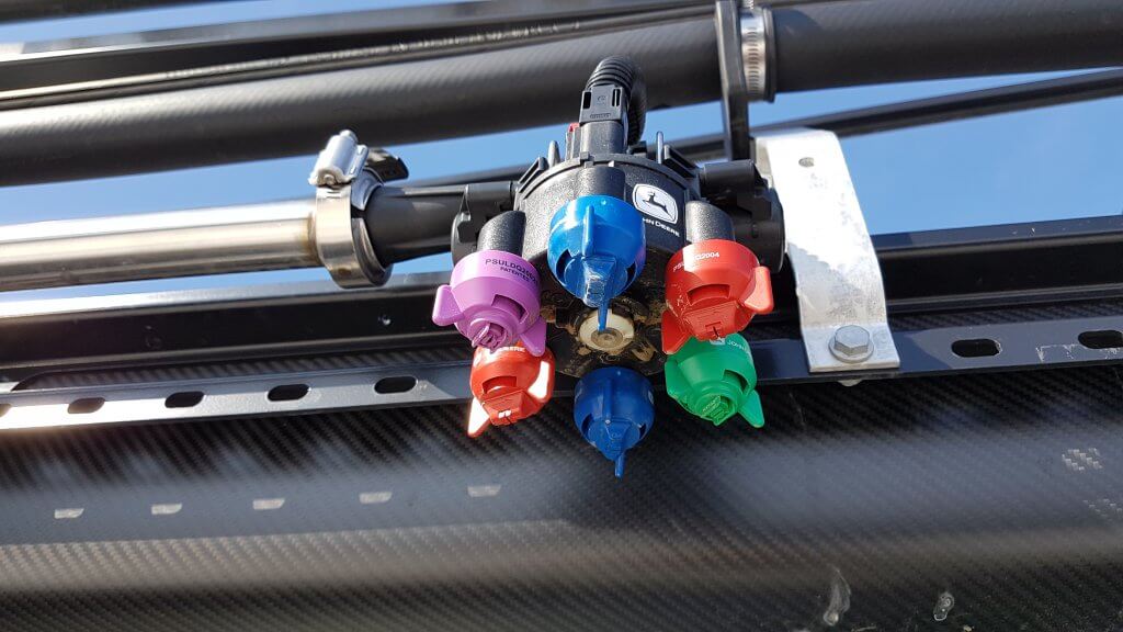
The body contains a turret with six numbered nozzle locations, all pointed down, and two solenoids, one on either side of the body. Three nozzle locations are on short feeds (locations 1, 2, and 3), whereas the remainder are on long feeds (4, 5, and 6). The front locations and left solenoid is called “A”, whereas the right solenoid and rear location is “B”.
ExactyApply nozzle body
Nozzles are paired so that A or B or both are capable of spraying at a time, depending on the selected mode. Pairs are 1 & 4, 2 & 5, and 3 & 6. The operator manually rotates the desired nozzle pair into position.
When a short feed (1, 2, or 3) is placed at the front of the body, the system is in Separated Mode. In this mode, the left solenoid controls the front nozzle and the right solenoid control the rear nozzle. Either or both can be used, in pulsing (PWM) or conventional mode, selected through the monitor.
When a long feed (4, 5, or 6) is placed at the front, the body is in Combined Mode. Now, all flow from the right and left solenoid can only exit the front nozzle. Very high flows are achievable in Combined Mode, making it suitable for liquid fertilizer application. It may not have other practical applications in Western Canada.
View from left side of body (solenoids removed). Turret position #4 (tall feed) is in front, and #1 (short feed) is in back, placing the body in Combined Mode.
In Pulsing Mode, each solenoid pulses at 15 Hz, meaning it completes 15 open-and-close-cycles per second. The A and B solenoid timing is offset by 180 degrees, so that the B nozzle is in the middle of its on-cycle when the A nozzle is in the middle of its off cycle. In combined mode, this means that the system operates at 30 Hz.
Adjacent bodies are also 180 degrees out of sync with each other, similar to Capstan, Raven, and TeeJet bodies, so that whenever a nozzle is off, its adjacent partners are on (when operating at 50% DC and above). Another way of saying this is that all even-numbered bodies act together, and all odd-numbered bodies act together but half a cycle later. This results in a blended pulse that prevents skips.
Plunger assembly inside solenoid. Black plastic portion can be removed, exposing poppet and spring.
The proportion of each cycle that the solenoids are open is known as the duty cycle (DC). At 100% DC, the valves are always open. At 50% DC, the valves are open 50% of the time. The minimum DC allowed by the system in default is 25%. This can be lowered to a smaller value within the monitor.
Opened plunger assembly showing tip of poppet (right) and seat (left)Poppet inside plunger assembly is pulled back by magnet inside solenoid 15 times per second
DC is closely related to the flow rate of the nozzle. There are two ways of looking at this. An 08 sized tip operating at 40 psi will have a flow rate of 0.8 US gpm at 100% DC, about 0.4 US gpm at 50% DC, and close to 0.2 US gpm at 25% DC. This feature is primarily useful when sprayer speed is changed, requiring new flow rates without a change in spray pressure.
Pulsing Mode is not available for nozzles sized smaller than 02, or for air-induced tips.
Pulsing can be disabled to allow the use of air-induced or other tip technologies that may not function well when pulsed. This is called AutoSelect Mode.
AutoSelect
Mode:
AutoSelect Mode (“Auto Mode” in 4600 monitor) can be used to achieve three unique flow rates. “A” alone, “B” alone, or “A” & “B”. When properly staggered, a travel speed range similar to Pulsing Mode can be achieved, although pressure will rise within each nozzle as travel speeds increase, as in a conventional system.
In AutoSelect Mode, the user selects a tip for position A, and an incrementally larger tip for position B. The monitor requires that the user inputs minimum and maximum pressures for A, B, and A&B. Travels speeds corresponding to these tip and pressure choices are calculated, and the monitor warns the user when speeds don’t overlap. The user either changes minimum and maximum spray pressures, or selects a different sized tip to eliminate the gap.
AutoSelect Mode is useful when a certain specific tip is required which is not compatible with Pulsing Mode, for example drift protection with air-induced tips.
Pulsing
Mode Nozzle Selection
At this time, John Deere nozzles best suited to the ExactApply’s Pulsing Mode are the LDM, LD, LDX, and 3D. Of these, the LDM most closely represents the spray quality of the LDA and ULD that John Deere operators are accustomed to. The remainder are considerably finer.
ASABE spray qualities for Low-Drift Max (LDM) tips. Being Very Coarse at lower pressures, applicators are advised to use higher spray pressures (50 to 70 psi) when coverage is important.ASABE spray qualities for Guardian (LDX) tips. Note that the smaller sizes (03, 04, 05) produce finer sprays and will require pressures below 40 psi to have any reasonable drift reduction. ASABE spray qualities for 3D tips. As with LDX, the smaller sizes (03, 04, 05) produce finer sprays and will require pressures below 30 psi to have any reasonable drift reduction. Such low pressures may narrow the spray pattern. ASABE spray qualities for Low-Drift (LD) tips. As with LDX, the smaller sizes (03, 04) produce finer sprays and will require pressures below 40 psi to have any reasonable drift reduction.ASABE spray qualities for the Low-Drift Twin (LDT). Comprised of two same-sized LD tips assembled in a TwinCap.
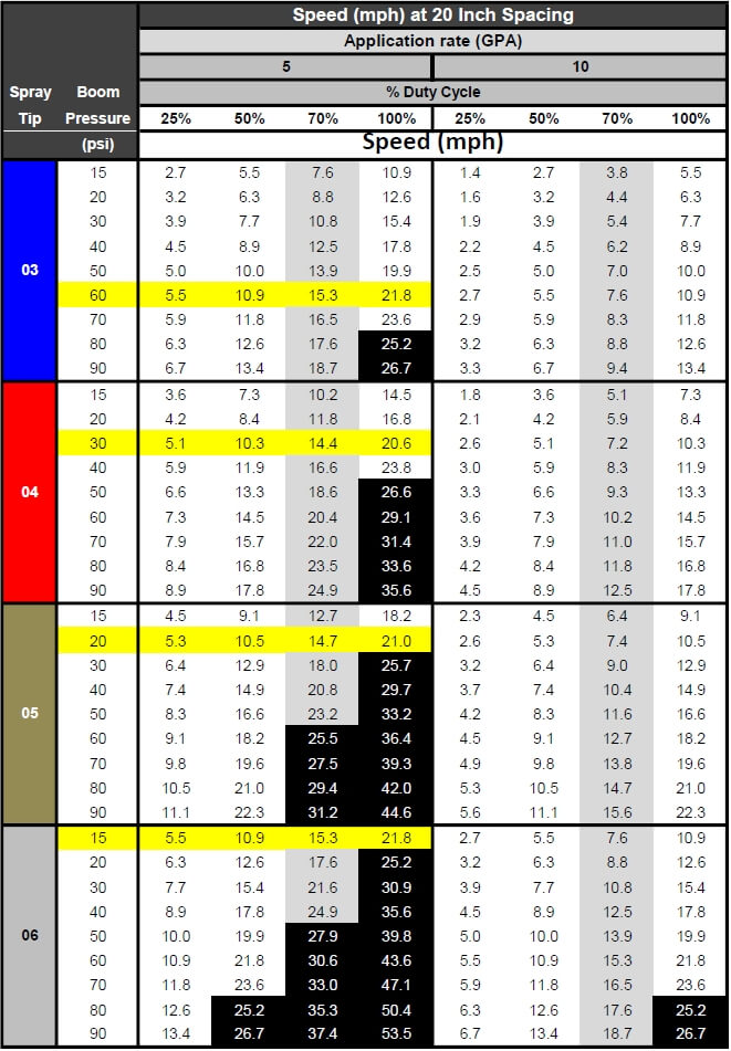
Proper sizing for PWM requires that tips be sized for about 20 to 40% extra capacity. In other words, at expected average travel speeds, the pulsing duty cycle should be approximately 60 to 80%. The following chart has a highlighted column at 70% duty cycle for that reason. Assuming an ExactApply operator expects to apply 5 gpa and travel at 15 mph on average, possible nozzle options (highlighted in yellow) are:
03 at 60
psi
04 at 30
psi
05 at 20
psi
06 at 15
psi
Calibration chart for PWM systems. Nozzles are sized at about 70% Duty Cycle (grey column). Options for 5 gpa at 15 mph are highlighted yellow. Black highlights represent speeds >25 mph, not available.
The best
choice will likely be either of the first two options, as the third and fourth
have spray pressures which are probably too low for good nozzle performance.
The decision would depend on the spray quality obtained for each of the
remaining two options.
Of
course, spray pressure can be altered to suit the operator’s spray quality
requirements. This merely affects the available speed range as well as the DC
at which the system operates at a given target speed, possibly affecting
Pulsing Mode utility.
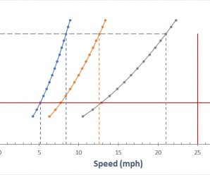
The row of speeds adjacent to the selected nozzle and pressure identifies the approximate travel speed range that can be expected, from 25 to 100% DC.
It’s important to know your current DC to be sure the system is operating properly, and also to take full advantage of turn compensation features. We’ve described a way to place a DC display module on your home screen here.
The application volume can be changed to suit the specific use, the chart’s speed values are updated automatically. Make sure the nozzle spacing at the top left is correct for your sprayer
Pressure
Drop across Solenoids
PWM
solenoids represent a restriction to flow, and may cause a pressure drop. John
Deere has published the pressure drop, and it is shown in the above chart
(download version only). The pressure drop is fairly low, only 2 psi for an 04
tip operating in separated mode at 40 psi. For an 06 tip, the drop is 3 psi,
and for an 08, it’s 6 psi. a #10 tip has a 10 psi drop at 40 psi. These
pressure drops must be added to the operating pressure of the sprayer. Pressure
drop is important because the LDX, LD, and 3D tips will be operated at low
pressures to obtain coarse sprays for drift protection. Operating an 08 tip at
20 psi (at which pressure it has s drop of 3 psi) will result in in a tip
pressure of 17 psi. Since we are at the low end of a nozzle’s operating range,
pattern stability may be compromised when the drop is not taken into account.
Why 70%
Duty Cycle?
An operator of any PWM system needs to know their current duty cycle. On ExactApply, a module can be installed on the home screen that provides a visual display. We show how to do this here.
There are
five main reasons a nozzle should be sized to run at approximately 70% DC. The
first is to provide speed flexibility. An operator may need to speed up somewhat,
but usually not more than 30%. On the other hand, slowing down is much more
common to accommodate challenging terrain, and a factor of two to three is
possible (from 70% DC to 25% DC).
Secondly,
drift reduction through lower spray pressure usually requires less speed due to
the associated lower flow rate. With some DC room to spare, the loss of flow
can be corrected without requiring a speed change.
Thirdly,
spot spraying at a slightly higher rate is possible, again through DC alone.
Fourth,
Nozzle Rate Boost of up to 25% for up to six nozzle locations is possible
within the monitor, but only if the system is operating at 75% DC or less.
Finally,
turn compensation, during which the outside boom travels faster than the
tractor unit and the inside boom slower, requires this additional capacity.
More on turn compensation here.
AutoSelect
Mode Nozzle Selection
AutoSelect
Mode allows for three flow rates to be used in succession: A, then B, the AB.
The key to success is to use small size increments between A and B, and to use
tips that have a wide pressure range.
In the
example below, the A location was an 02 tip and the B was an 03, for a total of
05. Pressure was not allowed to drop below 30 psi to retain good patterns.
Pressure at switch over to the next largest flow rate therefore needed to be 80
psi to make the moves possible without pressure gaps resulting in
over-application. As a result, the spray quality can be expected to fluctuate
three times as the sprayer accelerates through A, B, and AB in succession.
Nozzle
selection should seek to emphasize the middle of the pressure range of either B
or AB to avoid unnecessary fluctuations.
Spray pressure and travel speed as Auto Mode moves through A, then B, then both A&B
Download an Excel sheet that assists in nozzle selection for Auto Mode here.
A
maintenance kit comes with each ExactApply sprayer. It contains two spare
plunger assemblies, clips, and pins, as well as a brush, an O-ring picker, and
a torque driver.
Maintenance kit
The
ExactApply body is fairly easy to take apart for servicing. Hair pins at the
back of the unit secure each solenoid, and both pull out easily. The plunger
assembly can be disassembled without tools. Take care not to drop the poppet
spring!
Reassembly
of the plunger requires the use of the torque driver fitted with a 17 mm
socket, included in the kit. Do not over-tighten the plastic component.
Aside
from the manual rotation of the turret to select a different nozzle
combination, the only moving part in the ExactApply body is the poppet in the
plunger assembly. This piece is the valve that controls flow rate, and opens
and closes 15 times per second whenever pulsing mode is on, moving like a
piston in a cylinder. Debris (sand, fertilizer crystals, etc.) can interfere
with the seal of the poppet against its seat, and good filtration is important.
In the first generation, metal flakes began appearing inside some plunger assemblies . A coating de-laminates off the sleeve and can cause the plunger to stick. This has been starting at 800 h of use. The springs have also been observed to break. This problem has been addressed in newer generations.
Metal flakes interfering with plunger actionPlunger damage showing likely source of metal flakesBroken plunger spring
Certain formulations may build up a residue that interferes with poppet movement. It’s impossible to predict all possible formulation impacts, but oily formulations such as emulsifiable concentrates (EC, milky appearance) are likely to be more problematic than solutions (S, clear appearance). John Deere recommends a daily rinse of the boom through both the A and B valves with Erase, a tank cleaner product. Fortunately, the R series sprayer allow for boom flushes from the clean water tank even when the product tank has product in it.
Each nozzle body contains ten O-rings and two sets of seals. The turret assembly has two large rings, and each plunger assembly has four. Care needs to be taken to prevent damage to these rings to prevent leaks.
O-rings in nozzle body
Some
Recommendations
The
ExactApply system is very full featured and customers new to PWM can be
overwhelmed by the number of choices at their disposal. Let’s simplify the
system and make some basic recommendations.
Pulsing mode is likely to be the most useful feature of the system. Plan to use this feature for most spraying operations.
In Pulsing mode, select from John Deere’s LDM, LDX, LD, and 3D tips. The LDX, LD, and 3D offer similar Medium spray qualities and should be operated between 20 and 40 psi to produce lower-drift sprays. Check spray patterns at these pressures and ensure that 100% overlap is achieved (pattern width is twice nozzle spacing).
The LDM (Low Drift Max) is coarser than the above nozzles (comparable to ULD or LDA) and is available in 03, 04, 05, 06, 08, and 10 sizes. This will be the tip of choice for pulsing mode and can be used at higher pressures to ensure good pattern formation.
Separated mode can handle most flow rates, and offers the flexibility of choosing A (front tip) or B (rear tip) or both. This means turret 1, 2, or 3 will be in the forward (A) location.
Equip the A location with your low volume tip (say, 5 gpa). Place the high volume tip (say 10 gpa) at the B location. Use both together for late season sprays into dense canopies (in this case, A&B=15 gpa)
Twin tips for Fusarium Head Blight (FHB) can be achieved in five different ways.
3D tips in “A” or “B”, alternating their orientation along the boom (forward, backward, forward…). Pulsing Mode. (Since these tips are not very coarse, low pressures are needed to ensure that the angle of the spray persists more than a few inches).
3D tips in “A” and “B” on each body, front facing forward, rear facing backward, and operating in A&B. Pulsing Mode.
LDT (Low Drift Twin) in “A” or “B”. LDT is a TwinCap with two LD tips installed. Pulsing Mode.
LDM (Low Drift Max) in installed in a TwinCap in “A” or “B”. These are coarser sprays that will retain their direction longer and are well suited for FHB. Pulsing Mode.
GAT (GuardianAIR Twin), an air-induced tip, running in either conventional “A” mode or in Auto Mode but sized for “B” (avoid operating in A&B to prevent pattern interference).
Some recent recommendations: A customer wanted tips for 5, 10, and 15 gpa at 14 mph, and the 15 gpa was for FHB. He didn’t want to be too coarse. We recommended the LDM 03 at 60 psi (5 gpa) in “B”, the 3D 08 at 30 psi (10 gpa) in “A”, and both together, with the 3D facing forward, for FHB for 15 gpa. The sprays would be “Coarse”, a nice middle ground.
ExactApply joins Capstan PinPoint II, Raven Hawkeye, and WEEDit Quadro, Agrifact StrictSprayPlus, and TeeJet DynaJet with PWM capable systems. Auto Mode is a version of nozzle switching first introduced into the market as Arag Seletron and Hypro DuoReact. It appears to be a full-featured system that is fully integrated into the new John Deere 4600 display but is also available as a retrofit on the older R-Series 2630-equipped sprayers.