Listen to an audio recording of this article by clicking here
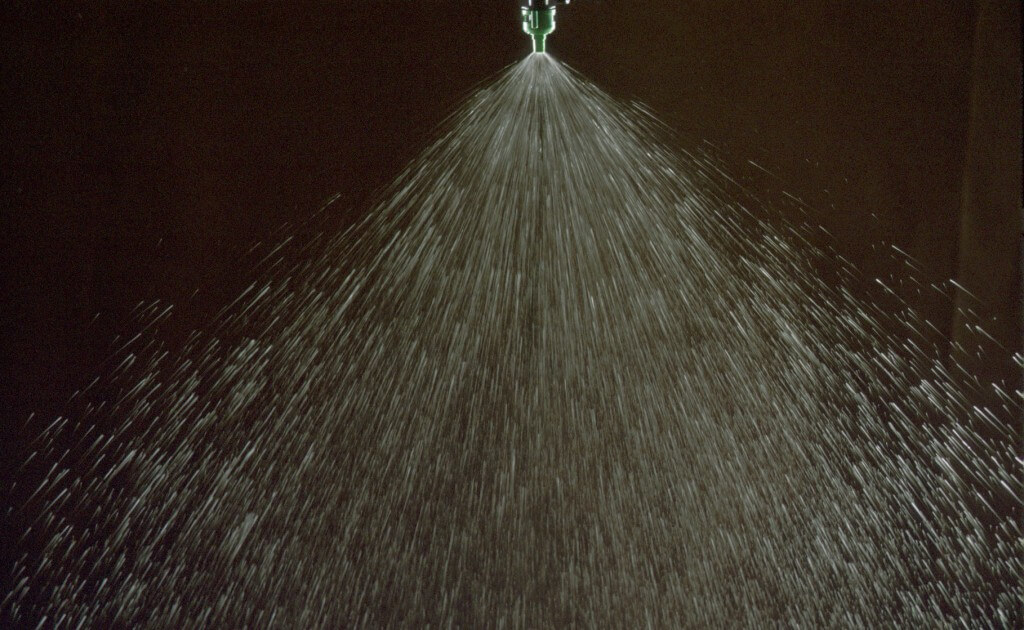
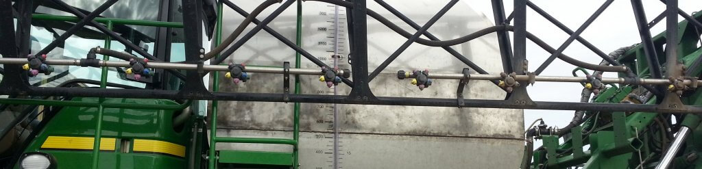
There’s a lot of talk about lowering the boom to reduce drift and make twin fan nozzles more effective. But how low can we actually go with a boom before striping becomes a problem?
We’ve done some calculating and have come up with answers.
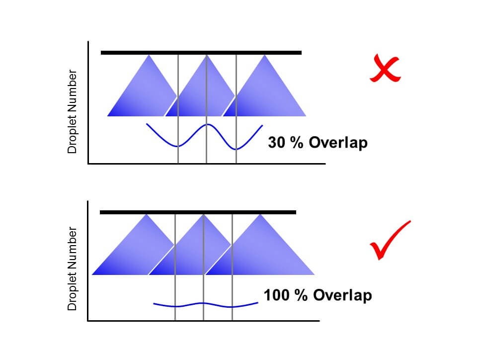
First, a few guidelines. Tapered flat fan nozzles require overlap to generate a uniform volume distribution under the boom. Traditionally, we’ve recommended 30 to 50% overlap with fine flat fan sprays. The small droplets tended to redistribute to fill in any gaps that might occur.
Overlap from fine sprays is less critical than from coarser sprays because the small droplets redistribute readily.
The advent of low-drift nozzles changed that advice. This nozzle type produces fewer droplets overall, and, like all fan-style nozzles, puts the coarser ones towards the outside edges of the fan. These don’t redistribute.
A typical flat fan spray places the coarser droplets at its periphery, and the smaller ones in the middle. When only the outed edges overlap, that can creates a band of poor coverage.
When we had 30% overlap and these two edges met, a region of relatively few, coarse droplets was formed, and this region contained almost no small droplets. On a patternator, the volume distribution was still good. But when we measured the droplet density, we saw a deficit in coverage at the overlap.
With low-drift nozzles, we need 100% overlap to distribute both small and large droplets uniformly under the spray swath. Too little overlap and we create bands of relatively few but large droplets that can cause striping.
Since then, we’ve been recommending 100% overlap for low-drift sprays. This means that the pattern width at the target will be twice the nozzle spacing, and all regions under the boom receive droplets from two adjacent nozzles.
With this adjustment, small droplets appeared throughout the spray swath, and striping was eliminated.
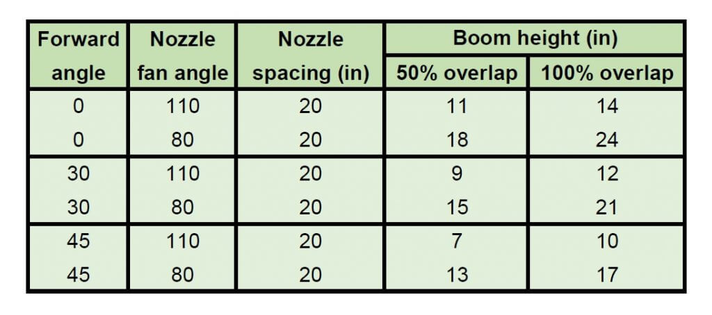
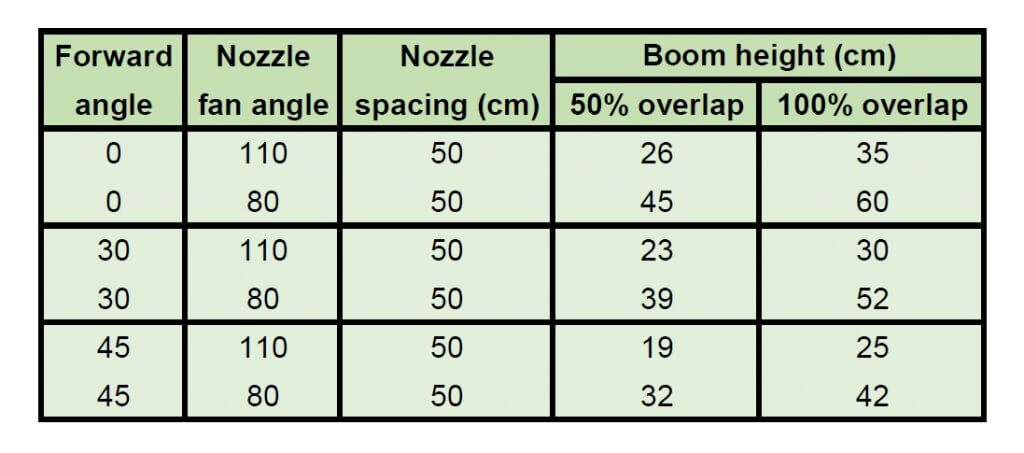
That leaves the question, just how low can a boom be set without creating this problem? The following tables provide some theoretical numbers.
Minimum boom heights for achieving 50% and 100% overlap of flat fan spray nozzles (US units) Minimum boom heights for achieving 50% and 100% overlap of flat fan spray nozzles (metric units)
A word of caution: The advertised fan angle on a sprayer nozzle often differs in practice. Not only will it be slightly different by design, it also depends on spray pressure and tank mix. As a result, it’s best to do a visual check. Set the spray pressure to the minimum you expect to use. Inspect the spray patterns and set the boom height so that the edge of each nozzle pattern reaches to the middle of the next nozzle. That means your pattern width is twice the spacing and will give 100% overlap. No tape measure required.
The tables were generated from a spreadsheet which can be downloaded here:
The values are theoretical and assume the fan angles are accurate. Some nozzles don’t produce the advertised fan angle. Enter your actual angle in the spreadsheet if you know it.
The theory assumes that the droplets at the edge of the fan always move in their projected direction. In fact, after some distance, say 50 to 75 cm, gravity pulls the droplets down and the pattern no longer widens at the same rate. The rate of pattern collapse depends on the droplet sizes.
Use the 0% overlap column to help with banding nozzle pattern width. Simply use the nozzle spacing column to enter your desired band width.
Note that angling the nozzles forward or backward decreases your minimum boom height, but depending on the deflection of the spray in the wind, this too has limits.
Too high a boom obviously increases drift. But patternation from overlap isn’t affected that much, largely because the pattern is now subject to aerodynamics and that becomes more important.
Pro Tip: Attach a length of plastic hose or a large zip tie to the boom, cut to your minimum boom height. This makes it easier to see what your boom height is, from the cab or the ground.
The bottom line is that a boom can be quite low and still allow excellent overlap and pattern uniformity from the nozzles. Yet we all know that most sprayer booms can’t reliably operate that low because they don’t control sway well enough. The ball’s in your court, sprayer manufacturers!
Use this spreadsheet to calculate the minimum boom heights needed for various applications.
Some caution:
The values are theoretical and assume the fan angles are accurate. Some nozzles don’t produce the advertised fan angle. Enter your actual angle in the spreadsheet
The theory assumes that the droplets at the edge of the fan always move in their projected direction. In fact, after some distance (say 50 to 75 cm, gravity pulls the droplets down and the pattern no longer widens at the same rate. The rate of pattern collapse depends on the droplet sizes.
Use the 0% overlap column to help with banding nozzle pattern width. Simply use the nozzle spacing column to enter your desired band width.
Note that angling the nozzles forward or backward decreases your minimum boom height, but depending on the deflection of the spray in the wind, this too has limits.
Too high a boom obviously increases drift. But patternation from overlap isn’t affected that much, largely because the pattern is now subject to aerodynamics.
Press play to listen to an audio version of this article
Agronomists help farmers manage their crop with advice on everything from crop cultivars to fertilizer rates to marketing. It’s challenging to be an expert on everything, but a few core competencies can go a long way to improving the level of service.
Agronomists are also responsible for communicating environmental
best practices. Along with fertilizer rates come messages of source, time, and
place, the 4R principles. The same is true for spraying, with messages of spray
drift, resistance management, and economic thresholds part of the consultation.
Let’s remember that we should not be indifferent to the potential consequences
of our recommendations.
Here are six skills that an agronomist should know about spray technology.
1. Recognizing major nozzle models and their spray quality and pressure requirements.
Application technologists are often asked to identify
nozzles and recommend spray pressures for clients. It’s a skill that anyone can
develop with just a bit of homework.
First, learn the colour-coding of nozzles – colours identify
flow rates and follow an international standard that all manufacturers have
adopted.
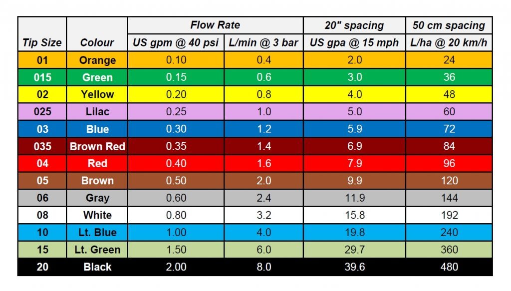
ISO Colour coding of major nozzle sizes, as well as application volumes at benchmark speeds.
Next, focus on the common nozzles on the major sprayers. John Deere sprayers will typically have three main air-induced nozzles, made for John Deere by Hypro, the Low-Drift Air (LDA), the Ultra Low-Drift (ULD), and the GuardianAIR Twin (GAT). Those with ExactApply, John Deere’s PWM system, will see the non air-induced 3D, the Guardian (LDX), and the Low-Drift Max (LDM). Recall that PWM flow control should not be used with air-induction tips.
Almost all Case sprayers have PWM, called AIM Command. Case uses Wilger ComboJet bodies and nozzles, with the ComboJet ER, SR, and MR most common, sometimes the DR or UR for dicamba.
New Holland/Miller with PWM (called IntelliSpray) are also likely to have these tips, but because these brands have TeeJet bodies on their booms, they require an adaptor for the proprietary ComboJet caps.
Otherwise, PWM units often use TeeJet’s TurboTeeJet (TT), Turbo
TwinJet (TTJ60), and Air-Induced TurboTwinJet (AITTJ60), the only air-induced
tip approved for PWM use by TeeJet.
Conventional spray systems (i.e., no PWM), will commonly
have (in alphabetical order) the Air Bubble Jet (ABJ, actually labelled BFS for
their manufacturer, Billericay Farm Systems), the Greenleaf AirMix (AM), the
Hypro GuardianAIR (GA), and the TeeJet AIXR.
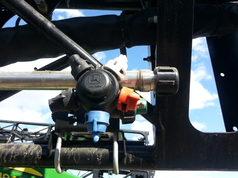
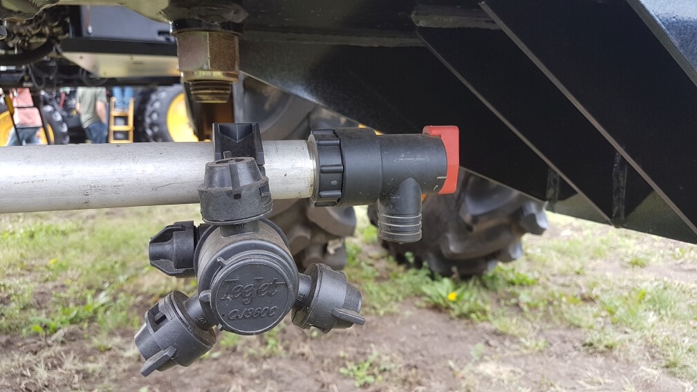
Many sprayers will have a twin fan for fungicides, primarily for fusarium headblight (FHB) management. The Greenleaf Turbo Asymmetric Dual Fan (TADF), the Hypro GuardianAIR Twin (GAT), and the TeeJet AI3070 dominate, as well as a number of custom configurations using splitters and twincaps.
Where dicamba is applied on Xtend trait soybeans, some special nozzles may be used to meet label requirements for coarseness. The TeeJet TTI is very common, but Greenleaf developed a special set of tips called the TurboDrop XL-D and the TADF-D. Wilger’s version, mentioned earlier, is the UR. John Deere has just announced their new ULDM.
That covers 95% of what you’ll encounter in the North American market. In Europe, add some Lechler nozzles (ID3, IDTA, IDK, IDKT) to the mix. In Australia, Arag is gaining ground.
Identifying the nozzles on sight is the prerequisite to
finding out their average droplet size, called spray quality. Often, the
inscriptions are worn off, so visual recognition is required to get there.
We’ve published a visual identification guide with pictures of the major nozzles here.
Knowing the relative spray qualities produced by these
various nozzles will get you bonus points, but you’ll need to do some extra
research to get there.
2. Using a spray calibration chart
This skill will make you popular on the farm and at the office. A very frequent question is “what size nozzle do I need for this new sprayer?”. The best way to approach the answer is to ask several questions.
Does the sprayer have 20” nozzle spacing? (90% of sprayers do).
What is the desired water volume?
What is the expected average travel speed?
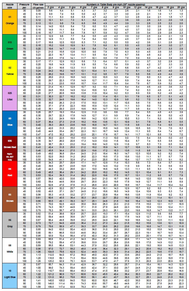
The first question guides you to the appropriate calibration chart, which can be downloaded here or can also be found in all sprayer catalogues. We explain how to use these charts here.
Calibration chart for 20: spacing, in US units.
If you don’t have a chart handy, use this shortcut: on a boom with 20” spacing, at 5 mph, every 0.1 US gpm capacity at 40 psi delivers 6 US gpa. So if you need to apply 12 gpa at 15 mph, an 06 size will get you there at 40 psi. That’s ballpark.
In metric, with 50 cm spacing, at 10 km/h every 400 mL/min (01 size) at 3 bar delivers about 50 L/ha. To deliver 200 L/ha at 20 km/h would require an 08 (white) tip.
Of course, if the tip is air-induced, make adjustments to speed or size to accommodate the higher pressure requirement of these types of nozzles.
Remember that spray pressure is key to performance, therefore the operator needs to drive at a speed, or use a volume, that results in the correct spray pressure.
3. Understanding Pulse Width Modulation
PWM technology has been on the North American and Australian market for two decades, but it remains poorly understood by those who do not use it. PWM will continue to gain popularity and has implications for nozzle selection and sizing.
Traditional rate control in the field involves the use of spray pressure to match liquid flow rates to travel speed. The rate controller knows the width of the boom (entered by the user), the travel speed (from gps), and the desired application volume (entered by the user). It does some math to identify the flow rate it needs, and compares that to the sprayer’s current flow meter reading. If the current flow is less than what’s needed, the sprayer increases pressure to increase flow. This happens continuously in the background.
When an operator speeds up, the pressure increases, and vice versa. As a result, the pressure (and therefore droplet size) will fluctuate with travel speed, and that can result in inconsistent spray patterns, coverage and drift.
PWM involves the installation of electronic solenoid valves at each nozzle body. These valves pulse on and off at 10, 15, 50, or 100 Hz, depending on the manufacturer. Each pulse contains a brief, complete shutoff of the flow. The proportion of the time the valve is open during a pulse is called the Duty Cycle (DC), and this is proportional to the flow through the nozzle.
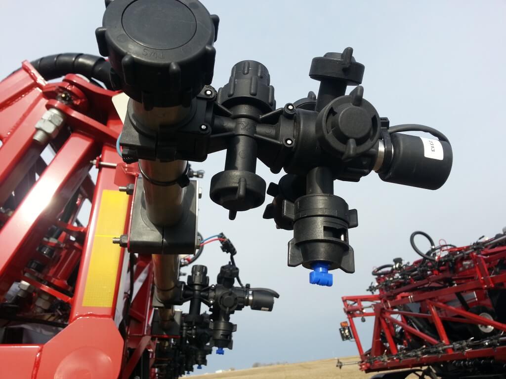
Capstan PWM solenoid on Case AIM Command
When the system requires more flow, it no longer increases pressure. Instead, it increases the DC. The advantage of this approach is that nozzle pressure can now stay constant, ensuring consistent coverage and drift.
There are other advantages of these systems. Each nozzle can be controlled independently, offering high resolution sectional control and turn compensation.
Nozzle selection and sizing are both affected by this technology. Nozzles need to be sized larger, with about 30 to 40% more flow capacity ideal. The DC will therefore run at 60 to 70%, optimal for speed fluctuations and turn compensation. Air-Induced tips are not usually recommended because their pattern deteriorates with pulsing.
We’ve written about PWM here, here and here to get you started.
4. Validating coverage of the target
A very useful indicator of the success of a spray operation is an assessment of “coverage”. This term refers to a qualitative combination of droplet density and percent area covered, and can be quickly assessed using water sensitive paper. We’ve explained the use of WSP here and here.
It’s very useful to have some of this paper on hand (available from any retailer that sells TeeJet or Hypro products, or on-line from Sprayer Parts Warehouse in Winnipeg or Nozzle Ninja in Stettler, AB). The coverage can be assessed in four different ways:
Water-sensitive paper being used to assess spray coverage.
using the “DropScope” scanner (gives a comprehensive assessment of coverage, density, size, plus image editing tools);
using a template of coverage examples;
using experience built on years of doing this.
Water-sensitive paper is also useful as a record, for
quality assurance. A spray application is conducted and part of the record is
an image of the deposit. Should a performance issue arise, this will help
settle it.
5. Understand basic sprayer plumbing
Often, a sprayer problem can be traced back to an issue with
its plumbing. There could be mysterious sources of contamination. The pump might
not be building pressure. The agitation isn’t running. Or you need to drain all
the remaining liquid from the tank.
Sprayer plumbing seems intimidating for a number of reasons.
It’s become complex on most modern sprayers. It’s hidden under the sprayer
belly. All the lines are the same black colour, so they’re hard to tell apart.
But it’s not as bad as it seems. Basic plumbing is the same
on all sprayers. The pump draws the spray mix from the bottom of the tank, the
sump. It may also have options to draw clean water from an external supply, or
from the clean water tank for wash-down.
The pressurized supply goes to three places:
to the booms, via sectional valves;
back to the tank, via a control valve that can be used to adjust the spray pressure;
to the wash-down nozzles.
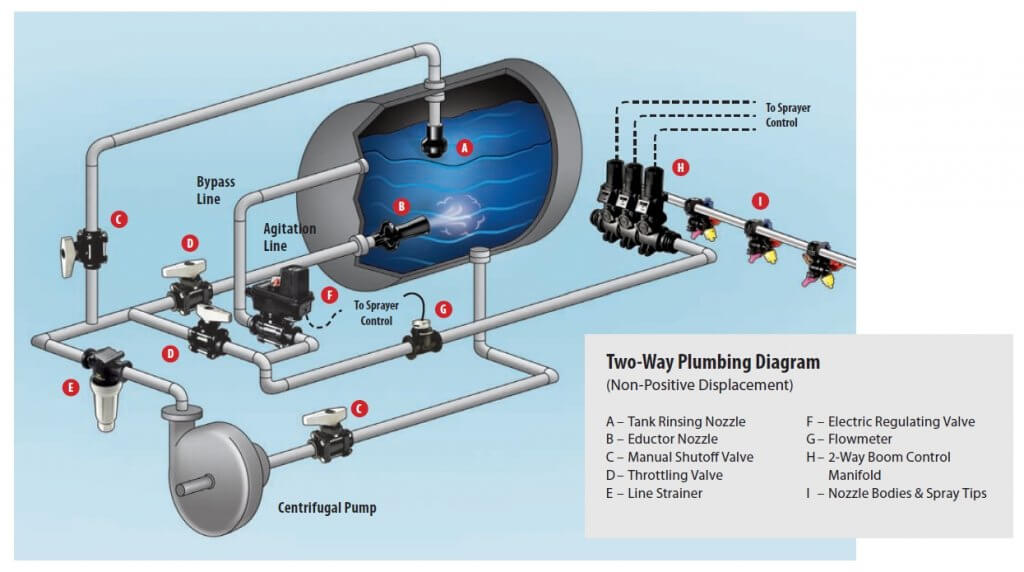
Typical sprayer plumbing for a centrifugal pump (Courtesy TeeJet).
When spraying, the less is returned to the tank, the higher the boom pressure. There may be several ways back to the tank, via agitation, via bypass (sparge), or via wash-down (used only when the pump draws water from the wash-down tank). Usually engineers can’t help themselves and introduce several what-if features that complicate the situation. But with a bit of know-how, and a flashlight, the plumbing system can be deciphered.
Pro tip: A centrifugal pump’s inlet (suction) is always the centre of the pump, its outlet (pressure) is at the periphery.
6. Matching a pesticide recommendation with application advice
It’s commonplace to recommend a specific crop protection product that matches the crop and pest situation. Recommending an ideal crop or pest stage improves the recommendation. But a truly successful outcome requires one additional step, advice on the application method. The customer may need to know if product performance depends on water volume and droplet size. Some products are more sensitive to this than others. Perhaps there is a specific nozzle type that may be helpful.
The classic example for application method is Fusarium headblight in wheat. The basics are straightforward. An agronomist recommends the fungicide, and guides the tight application window with a field visit to stage the crop, plus a look at the disease risk forecast map. But true application success requires an angled spray, with a coarser spray quality plus relatively low boom height to make it all worthwhile. That’s a full-featured recommendation.
Common herbicide applications also benefit from additional
information. Some tank mixes and weed spectra allow for coarser sprays than
others, and the ability to spray coarser means a wider application window and
therefore more accurate timing. Other tank mixes may pose a significant risk to
drift damage, requiring special measures to prevent a problem. Identifying
those opportunities adds value.
Water volume and spray quality recommendations for major herbicide mode of action groups.
Newer labels for dicamba (Xtendimax, Engenia, Fexapan) and 2,4-D
(Enlist Duo) have very specific instructions for drift prevention. This
information must be shared with customers to ensure that their drift liability
is covered.
Are there other skills that you feel agronomists should have?
Please share them with us by contacting us at the bottom of this page.
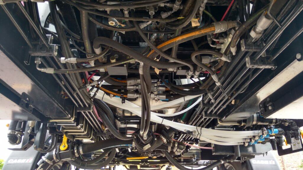
A lot of people are intimidated by sprayer plumbing. One look at the spaghetti bowl of spray mix and hydraulic hoses and valves, and they walk away. It hasn’t helped that much of it is concealed under the frame and all of it is in the same black colour, so figuring it out on your own is almost impossible.
Belly of a typical sprayer, showing black hydraulic and spray hoses.
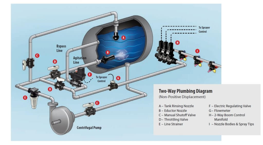
Let’s quickly review the basics. In all sprayers, the liquid in the tank is drawn out from the bottom and pressurized by a pump. The pressurized liquid is split into two main paths. One goes to the spray boom to hydraulic atomizers (nozzles). The other goes back to the tank to agitate the liquid and act as a pressure bypass when the booms are off. Bypass throttling changes pressure. That’s it.
Sprayer plumbing diagram (Source: TeeJet).
By the way, has anyone ever thought of some colour-coding or labelling the hoses and valves on a sprayer? We’d definitely appreciate that.
Conventional boom sections
Most North-American sprayers feed the pressurized liquid to the boom, where the flow is subdivided into physical sections that define the various portions of the boom that can spray at any one time. Older sprayers might only have two sections, the left and the right boom. Wide booms now have anywhere from 5 to 13 sections, each about two to four metres wide. Each section has a pressure feed to its middle, and each section terminates at two dead ends, at which we place caps or valves for flushing.
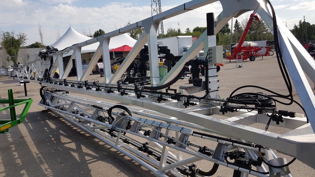
A conventional plumbed boom with two sections. Each section has two terminal ends that require cleaning. Boom can only be flushed or primed by spraying or by opening boom end caps.
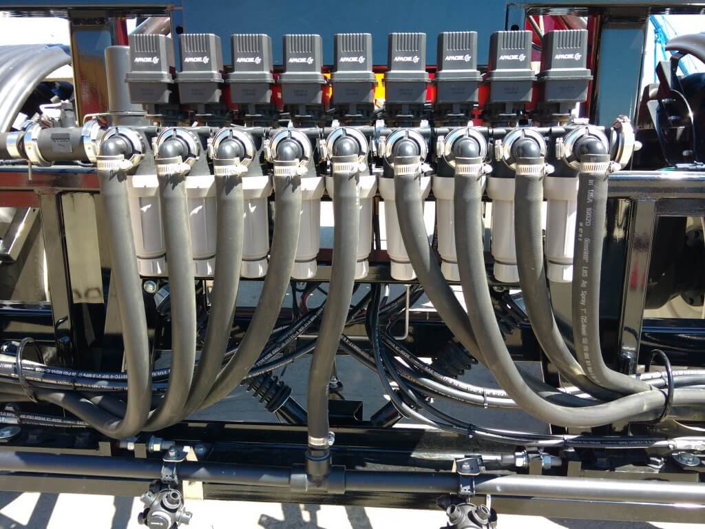
Sprayer with nine sections, each controlled by its own valve and each running a dedicated feed hose.
Two partial boom sections, each showing a central feed line and a capped boom end.
Sectional boom end showing 10 cm of capped pipe beyond last nozzle body.
Boom end with valve to facilitate draining and flushing.
Any liquid that enters this type of boom must exit at the nozzle or the boom end. It must be sprayed out or drained. This poses three distinct problems.
If the boom contains water or a previous spray mix, the boom needs to be primed with the new product before spraying. We need to spray or drain the existing product out.
If we want to clean the boom or flush it with water, again we need to push the existing liquid out.
If we have dead spots in the boom section, such as a boom end, we need to take special care to flush those out as well.
These characteristics complicate cleaning, create waste or contamination, and take time.
Recirculating booms
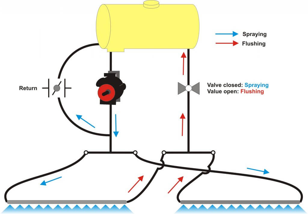
In a recirculating boom, the spray mixture enters the boom at one end and exits at the other, returning to the spray tank. In most cases, the left and right wing each has its own feed and return. Sectional control is achieved via individual valves (air or electric) placed on the nozzle bodies.
There are two main types of recirculating booms on the market.
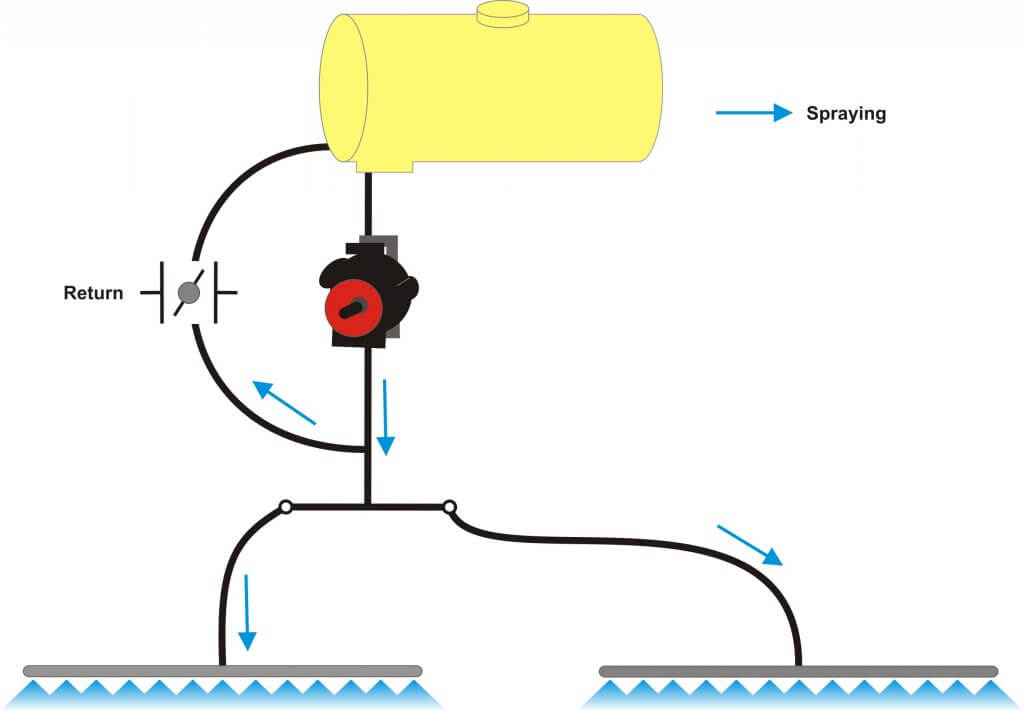
The first system routes the pressurized mixture into the boom and shuts off the return line during spraying. When the nozzles are shut off for a turn, the return line opens automatically and the boom flow is pushed past the nozzles back to the tank. When the nozzles spray again, the return line closes to pressurize the boom.
Recirculating boom system offered by Pommier. One end of boom is pressurized, the other end is return. Return flows when boom spraying is shut off. Boom can be primed or flushed without spraying.
This is the system used by Pommier, the French aluminum boom manufacturer who first introduced recirculating booms to North America.
Pommier recirculating boom.
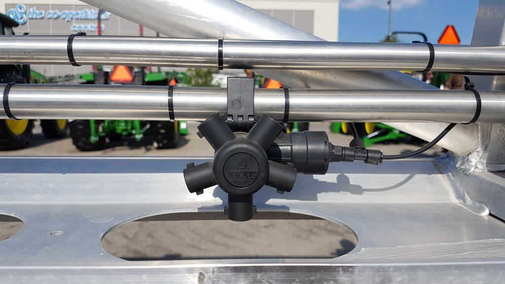
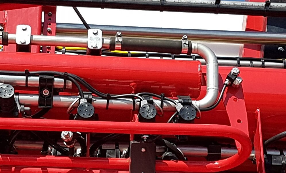
Pommier boom showing stainless steel supply and return lines, as well as air-activated shutoff valve on nozzle body.
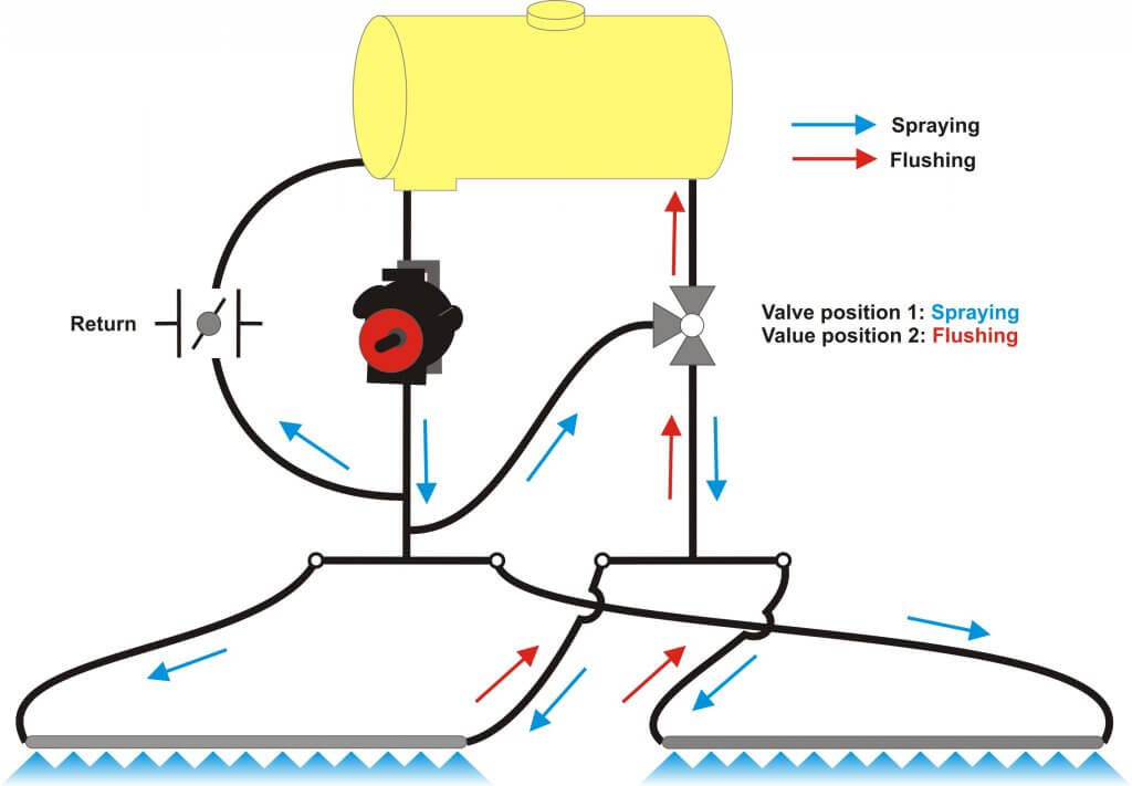
The second type of system contains a 3-way valve, connected to the return line and the pressure side of the pump. This valve provides the option of either allowing the return line to go back to the tank, as above, or to also allow pumped flow to the return side so that the boom is pressurized at both ends.
Recirculating boom that allows return line to be either pressurized by pump, or return to tank.
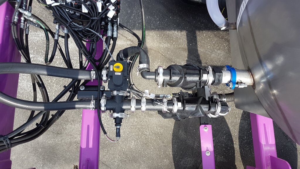
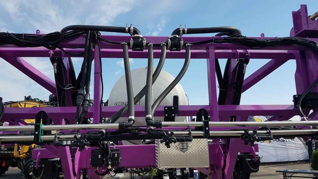
Top view of D.O.T. Connect sprayer recirculating boom setup. Lower line is pressurized by pump. Upper line is return. Three-way valve allows return line to either go back to tank, or be pressurized by pump.
Tidy setup of pressure and return lines on D.O.T. Connect system.
This feature may be useful with long booms along which pressure drop is more likely to occur, or when very high flows are required, and was introduced to North America by the Dutch manufacturer Agrifac, about which we wrote here and reprinted Mick Robert’s article from Pro Operator here. A similar system is available from Rogator (starting in 2018) via their C-Series featuring LiquidLogic. It has also been used on the Connect sprayer, developed by Pattison Liquid Systems, for the D.O.T. autonomous platform.
The main advantages of this design are that it provides the option of additional pressure to the spray boom to avoid pressure drop, and to allow any spray mix in the return line to be pushed and sprayed out to the boom for rinsing in the field. This lowers the remaining volume that needs to be diluted.
Agrifac recirculating boom showing return loop at boom end.
Boom end on Rogator Liquid Logic system. Note Hypro Pro-Stop E shutoff valve.
Features
Recirculating booms offer advantages in terms of preventing soil and water contamination and also in terms of simplifying the boom cleaning process. The design provides an opportunity to graduate to a better resolved sectional control as well due to the requirement for individual nozzle shutoff valves.
Due to shorter and less complex lengths of plumbing needed, stainless steel can be used for the return lines which decreases the potential for pesticide residue being adsorbed.
To rinse a boom with product mix still in the tank, simply draw water from the on-board clean water tank and push it to the boom without activating any nozzle bodies. The mix in the boom is returned to the tank and replaced with water, nothing is sprayed or drained. The tank contents may become slightly diluted depending on the duration of the rinse.
To rinse the tank as part of the sprayer cleanout, first spray the tank empty. Then introduce clean water into the product tank via the wash-down nozzles and spray that out. As always, either use several batches of small clean water volumes, or a continuous rinse system, to dilute the remainder most effectively. There may be additional volume to dilute from the return lines compared to a conventional system, depending on the type of recirculating system is used. However, boom ends no longer exist and this saves effort and ensures a more thorough rinsing.
To prime a boom that contains water, simply open the return lines back to the tank and allow the new mix to flow through the boom. Again, some dilution of the tank will occur due to the water in the boom.
The value of spray-free rinsing and priming adds up. Each prime, for example, consumes about 30 US gallons before the spray reaches the last nozzle of the longest section. Much of that product ends up on the ground, probably while the sprayer is stationary, and probably in a similar place on the field year after year.
Since a recirculating boom requires a powered individual nozzle shutoff, this adds some cost. However, the opportunity of improved sectional control via virtual sections is significant (most monitors offer 16 virtual sections that can be configured). Well-configured virtual sections can save several percent from overlaps.
Recirculating booms remove many of the contamination problems associated with conventional plumbed sections. They save time, money, and reduce environmental impact. We think they should be offered on sprayers.
Here’s a link to a nice article on recirculating booms written by Spencer Myers for the Manitoba Co-operator. A video that goes with the article can be found here.
Some pesticide labels require or prohibit certain droplet sizes to reduce the potential for drift. But, even when labels are silent about size restrictions, operators should be aware of the potential for droplet size to affect coverage. In the case of airblast, droplets should be:
large enough to survive evaporation between nozzle and target.
small enough to adhere without drifting off course.
plentiful enough to provide uniform coverage without compromising productivity (e.g. affecting refills and travel speed).
Once spray leaves the nozzle, the operator has no more control over the application, so it’s important to plan for as many contributing factors as possible. Deciding which nozzles to use (and yes, you have alternatives beyond disc-core), requires an understanding spray quality symbols and basic droplet behaviour.
Spray Quality
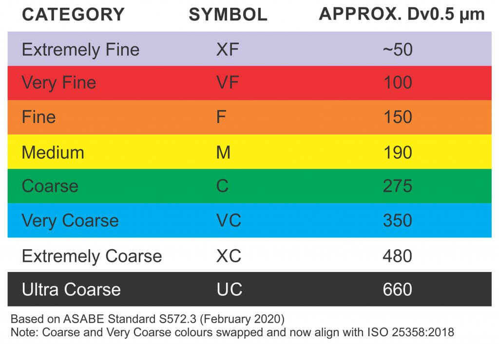
Droplet diameter is measured in microns (µm). For a given pressure, a nozzle creates a range of droplet sizes which are described by the American Society of Agricultural and Biological Engineers (ASABE) standard S572.3 (Feb. 2020) In North America, these spray quality ratings range from “Extremely Fine – XF” to “Ultra Coarse – UC”. For interest, the scale is based on the British Crop Protection Council (BCPC) system, which is slightly different.
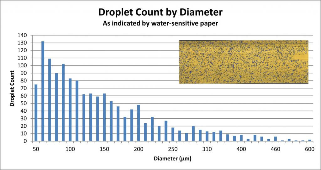
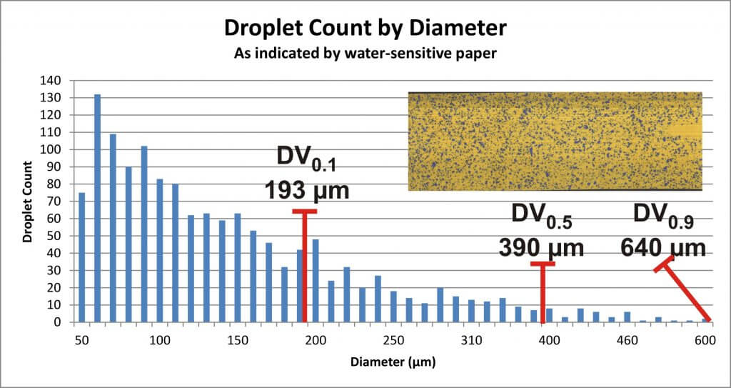
To make sense of the spray quality rating, we must first understand that not every droplet produced by a hydraulic nozzle is the same size. We noted that a single nozzle produces a range of droplet sizes. Spray quality captures that span using a few key metrics. The first is the Volume Median Diameter (VMD) or DV0.5. Think of it this way: Let’s say you have a hollow cone nozzle that breaks a volume of liquid up into droplets. Let’s arrange them from finest to coarsest as in the following graph.
The DV0.5 refers to the droplet size where half the spray volume is comprised droplets smaller than the DV0.5, and the other half is comprised of larger droplets. But we need more to understand the variation in the population. In other words, are they all the same size, or do they vary a great deal?
That’s why we also assign a DV0.1 which tells us the droplet size where 10% of the spray volume is comprised of smaller droplets, and a DV0.9 which indicates that 10% of the spray volume is comprised of larger droplets. Let’s add them to the graph:
With all three numbers, we can calculate the Relative Span (RS) by subtracting the DV0.1 from the DV0.9 and dividing by the DV0.5. The smaller the resulting number, the less variation there is in the spray quality. Two nozzles might produce a range of droplets with the same DV0.5, but the one with the larger RS is more variable, and is more likely to drift. Since we don’t typically have access to the RS of each nozzle, we rely on the spray quality symbols in nozzle catalogues to alert us to potential drift issues.
Relative Droplet Size
Did you notice in the graph that there are a lot of Fine droplets compared to Coarse? Disc-core (or disc-whirl) nozzles do not have spray quality ratings, and moulded hollow cones may or may not. This is, in part, because the standard was developed for flat fan nozzles, but mostly it arises from the nature of airblast spraying. No matter the original droplet diameter, the air shear from the sprayer and the distance-to-target reduce the DV0.5 considerably by the time spray reaches the target. It is safe to assume that the final spray quality will be much finer than the nozzle’s rating.
Incidentally, this is a big difference between boom sprayers and airblast: Where the boom sprayer operator should be aware of how pressure affects droplet size, it’s of little consequence to an airblast operator. On an airblast sprayer, pressure really only affects nozzle rate.
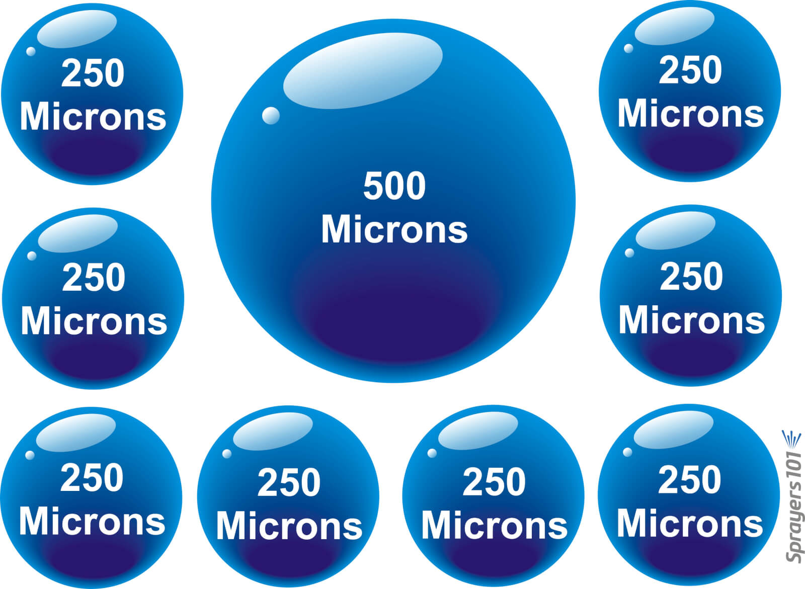
So, while shear and evaporation raise drift potential, shear also increases droplet count. Imagine the volume a nozzle emits as a cake. No matter how many slices you cut the cake into, you still have the same amount of cake. The finer the slices, the more people can have a slice, albeit not very much. Similarly, a single Coarse droplet can contain the same volume as many finer droplets. Mathematically, a droplet with diameter X represents the same volume as eight droplets with diameters of 1/2X. See the illustration below:
The eight to one rule: Every time the diameter of a droplet spray is doubled, there are eight times fewer droplets. Conversely, every time the diameter of a droplet is halved, there are eight times more.
Droplet Behaviour
The droplets that comprise the spray behave differently from one another. Finer droplets have a low settling velocity, which means they take a long time to fall out of the air. Conversely, coarser droplets fall out of the air more quickly. Think of how a ping pong ball (the finer droplet) has much less mass than a golf ball (the coarser droplet). When thrown into the wind, the golf ball follows a simple trajectory before falling. The ping-pong ball behaves erratically, like a soap bubble. Wind, thermals, humidity and many other factors will change where it goes because it is too light to resist them. It may even land behind the thrower, blown by the prevailing wind.
It is because of the behaviour of finer droplets, and the airblast sprayer’s inclination to create them, that we must be so diligent when we adjust the air settings.
We once explored this at a nursery workshop. The operator was spraying whips, which are young trees with very few lateral branches. He used a cannon sprayer to cover 30 rows (15 from each side) and felt he would incur less drift if he just used pressure, not air, to propel the spray. Water sensitive paper exposed the erratic coverage that resulted. Coverage uniformity was greatly improved when air was used, even when only spraying from one side of the 30 row block. Of course, this was only to demonstrate a principle; we don’t recommend alternate-row-middle-spraying.
Air-induction nozzles can be used to increase the median droplet size on an airblast sprayer. When used in the top nozzles positions, the coarser droplets that miss the top of tall targets will ultimately fall (reducing drift). They can also be used in positions that correspond to restricted airflow. In this case the operator relies on pressure to propel the coarser droplets where there is limited air to carry finer droplets.
Conclusion
The net result of all this is that the sprayer operator must choose a nozzle, pressure, and travel speed while considering the effect of distance-to-target and the weather. The resultant range of droplets should be fine enough to increase droplet count and be carried by sprayer air to deposit uniformly throughout the canopy. However, droplets should also be coarse enough to reduce drift if they miss.
Hey, if it was easy, anyone could do it!
Move ahead to 29:40 to watch a video describing how droplets behave an misbehave. Ahhhh Covid-hair. It was a thing.