All sprayers experience a drop in pressure as the solution moves further away from the pump. Here’s why that’s important, and how to measure it.
Optimal nozzle operation in terms of spray quality and fan angle is closely tied to spray pressure. As we try to maximize travel speed range with a modern sprayer, we often push spray pressure to its limits on the low and high side. For many air-induced nozzles, spray quality and fan angle become critical at about 30 psi. We need to be sure about the exact nozzle spray pressure to prevent problems.
Pressure drop is caused by the friction that the spray solution experiences as it moves from the pump to the spray nozzles. It’s caused by a number of factors, including length of tubing, elbows, valves, screens, and other flow obstructions.
Plumbing components add friction to liquid flow. If the pressure gauge is installed before these components, the nozzle pressure is unknown but will be lower than the gauge reading.
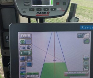
The pressure transducer that reports pressure to the cab is usually located between the pump and the manifold that divides the spray into the various boom sections. At this point, the spray liquid hasn’t experienced any significant flow restrictions. The transducer basically reports pump pressure.
Once the spray mixture starts moving through boom sections towards the nozzles, it encounters those restrictions, and pressure at the nozzle will therefore be lower than the cab reading indicates. The higher the liquid flow, the greater the friction, and therefore, pressure loss.
Even older sprayers with only two boom sections (left and right) and few elbows and reducers, will see pressure losses due to the narrow and long boom pipe that feeds up to 60′ on each side.
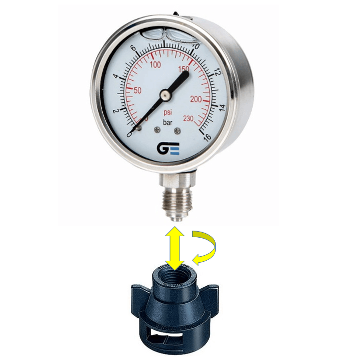
The nozzle pressure can be measured with a gauge placed on a nozzle body. Simply purchase a quality gauge and a threaded nozzle cap, combine the two and install in place of a nozzle.
A pressure gauge threaded into a nozzle cap can measure boom pressure.
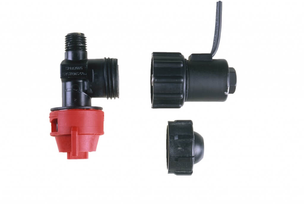
Operate the sprayer at your expected spray pressure (say, 60 psi) with all boom sections on. Install the portable pressure gauge on an open turret position and turn into place, noting its reading. If both gauges are accurate, the boom pressure will likely be below 60 psi.
The difference between the cab gauge pressure and the boom gauge pressure two is the pressure drop. Repeat the measurement for each boom section. Also repeat at your lowest, as well as your highest expected flow rates. Higher flow rates cause greater pressure drops.
Now, use this information to adjust your interpretation of the cab pressure reading. For example, if you want to spray at 60 psi and your pressure drop is 10 psi, then the cab pressure should read 70 psi.
If your boom pressure is higher than your cab pressure, and you’ve checked the accuracy of your new boom gauge, then don’t be too mystified. Your pressure transducer is malfunctioning.
This exercise is important if you’re trying to compare your nozzle flow to the expected nominal flow of the nozzle – perhaps you’re trying to determine nozzle wear. The nominal flow of agricultural nozzles is determined at 40 psi, so it will be important to measure the flow at exactly that pressure.
By measuring pressure drop on all your boom sections, you also get a good sense of the variability in pressure across your boom. Your measurements might reveal an obstruction or a hose kink somewhere along the line.
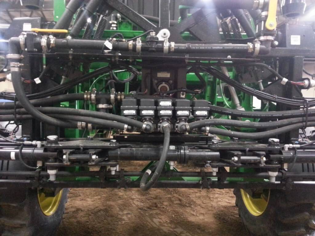
Note that the pulse-width modulated systems offered by Capstan, Case, and Raven use a solenoid at each valve. This solenoid adds a known, and significant, pressure drop to the spray system as can be seen here.
Pulse-Width-Modulation (PWM) solenoids typically have internal flow restrictions that can contribute to pressure drop.
Here’s a fun video filmed by the Ontario Pest Education Program during a break at Ontario’s Southwest Crop Diagnostic Days:
Automatic rate controllers are standard equipment on almost all new sprayers. They ensure consistent application volumes, but they don’t do all the thinking for you. We explore how to make them work properly.
A rate controller needs to know the boom width (entered by the user), the total spray liquid flow rate (from a flow meter), and the sprayer speed (gps, radar). It controls the spray liquid pressure by opening or closing a bypass valve. More pressure equals more flow to the boom.
The rate controller allows the applicator to enter a desired application volume and the controller sets the spray pressure that gives the necessary flow for the application volume and sprayer travel speed being used. In practice, this means that higher travel speeds result in higher spray pressure, and vice versa.
But it’s not that simple. Rate controllers aren’t smart enough to know how pressure affects nozzle performance. Some nozzles don’t work well at low pressures. Others do a poor job at high pressures. Some sprayer pumps may even have a problem generating some of the higher pressures a rate controller calls for. What does that mean for the available travel speed range that’s possible with any given nozzle? To answer that question, we first have to have a closer look at how pressure affects nozzle performance.
Spray Pressure and Nozzle Performance
Nozzle performance depends on a number of factors. Of these, the most critical is spray pressure. Pressure affects the flow rate of the nozzle, the spray pattern (fan angle) and the spray quality (droplet size range). The last two of these affect coverage, overlap, and spray drift, so it’s important to get them right. Each nozzle model has a unique spray pressure range and unique spray qualities within that range, so one must obtain information that is specific to the nozzles on the spray boom from the nozzle manufacturer.
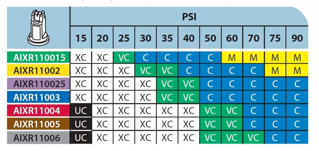
ASABE spray quality for the TeeJet AIXR nozzle.
Catalogues Contain Important Information
Nozzle manufacturer catalogues identify the pressure range over which the nozzle should be operated. At low pressures, engineers look for a uniform pattern that meets the advertised fan angle. The upper pressure limits are kept low enough to prevent the formation of excessively fine sprays. Manufacturers now publish tables containing “Spray Quality”, a broad categorization of droplet size, for their various nozzles and spray pressures in their product line. Common spray qualities for agricultural nozzles are Fine (orange), Medium (yellow), Coarse (blue), Very Coarse (green), and Extremely Coarse (white). An example table from a catalogue is shown in Figure 1. Note that for any given nozzle flow rate (left column), the spray quality changes with spray pressure. For example, the TT110025 nozzle can produce a Very Coarse or a Fine spray, depending on the pressure. Also note that for any given pressure, higher flow rate nozzles produce coarser sprays. At 40 psi, the TT nozzle can produce a Medium, Coarse, or Very Coarse spray, depending on its nominal flow. Both of these relationships depend on the nozzle model and manufacturer.
Speed-Pressure-Spray Quality Relationship
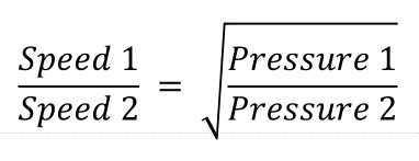
As we increase spray pressure, flow rate increases with a square-root relationship.
The square root relationship between travel speed (or flow rate) and spray pressure for hydraulic nozzles
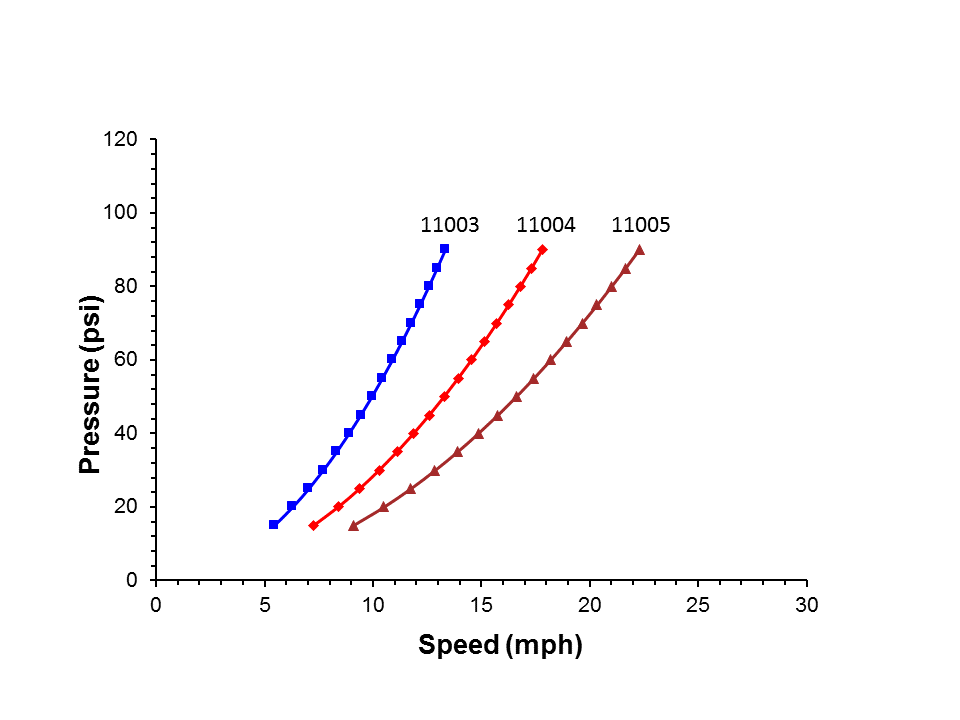
This means that in order to double the flow rate, we need to increase spray pressure by a factor of four. Figure 2 shows three different flow rate tips, each applying 10 US gpa at a range of travel speeds. Assume the operator uses a AIXR11004 to apply 10 US gpa at 12 mph. The nozzle would operate at about 40 psi, producing an Extremely Coarse spray quality. If the sprayer slows down to 7 mph to initiate a turn, spray pressure will drop to 15 psi, producing an Ultra Coarse spray. The spray pattern would likely become noticeably narrower, and poor pest control performance is likely in this situation due to the coarseness of the spray.
Relationship between travel speed and spray pressure for three nozzles applying 10 US gpa
It would have been better to use the AIXR11003 nozzle. At 12 mph, this nozzle would have operated at about 70 psi, producing a Coarse spray. Slowing down to 7 mph would drop the pressure to 25 psi, producing an Extremely Coarse spray. If the pesticide being used is sensitive to spray quality, then perhaps such slow speeds should be avoided in order to maintain a higher pressure and finer spray.
The lesson from this exercise is three-fold: (a) size the nozzle to operate at a higher pressure at your target speed to avoid dropping the pressure too low when you slow down, (b) avoid going as slow as 7 mph to prevent the pressure from dropping too low (c) compromise by setting a minimum spray pressure on the rate controller, in which case you’d over-apply product somewhat when their speed dropped too low.
Spray Pattern Overlap
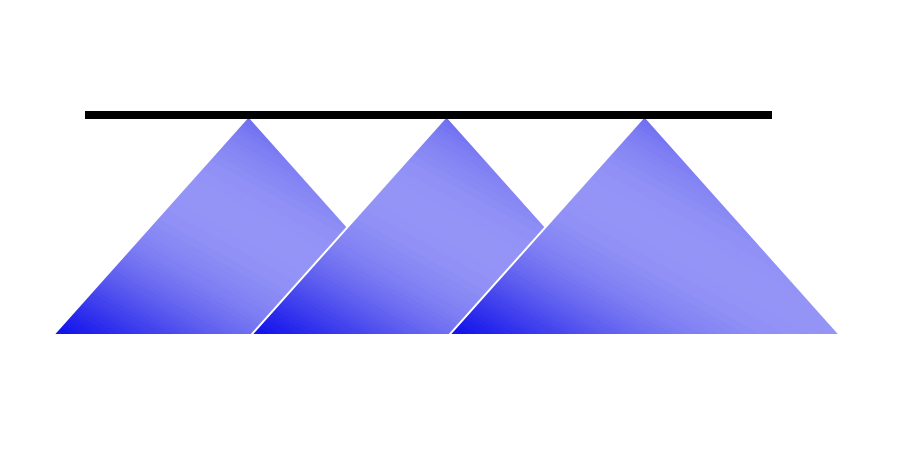
Flat fan nozzle patterns need the correct overlap in order to achieve a uniform spray pattern under the boom. Research has shown that the amount of overlap for low-drift nozzles needs to be at least 100% to achieve optimum nozzle performance. In other words, the edge of a fan should reach into the centre of the adjacent fan (Figure 3), with each fan covering twice the nozzle spacing at target height. This amount of overlap assures that not only the spray volume is uniformly distributed, but that the droplet density is equally uniform. Less overlap may result in fewer droplets depositing in the overlap region, resulting in poor coverage and reduced pesticide performance.
100% overlap means that all areas under the boom receive spray from two adjacent nozzles.
Adjust the boom height so that at the lowest expected spray pressure (slowest planned travel speed), the nozzles still achieve 100% overlap. There is no disadvantage with greater than 100% overlap, but higher booms will lead to greater drift. When a choice exists, choose 110º fan angle nozzles. Most air-induced nozzles are produced at one (usually wide) fan angle only, but actual angles often differ from those advertised. It is important to visually check the overlap before spraying.
Recommendations
What does this mean in practice? Spray operators need to know the right spray quality for the job, and should consult with the pesticide product manufacturer. They also need to use nozzle manufacturers’ charts to identify the spray quality their nozzle will likely produce at their expected application volume and travel speed. If it’s a poor match, a different nozzle may need to be found. Here are some rules of thumb:
Choose a nozzle that produces a Coarse spray over most of the operating pressures you expect to use. Although Very Coarse sprays can work in most situations, avoid them when using lower water volumes, controlling grassy weeds, or using contact modes of action.
Minimize spray drift by avoiding nozzles or pressures that produce Medium or Fine spray qualities.
Make your pressure gauge your speedometer. First, choose a pressure that is in the middle of the nozzle’s recommended operating range. If the range is 15 to 90 psi, select 50 psi. If it’s 40 to 100 psi, select 70 psi. This allows you slow down or speed up somewhat without breaching the nozzle’s capabilities.
Identify the travel speeds that are possible without creating spray qualities that could compromise your application goals.
Visually inspect the spray pattern at the pressure extremes you expect to spray at. At the lowest pressure, your nozzle should still produce 100% overlap (the edge of the spray fan should come to the middle of the next nozzle at target height). If it doesn’t, choose a wider fan angle nozzle, increase spray pressure or elevate the boom.
Make sure your pump can produce the higher spray pressures you expect to need. Pressure limitations are greatest at high flow rates (fast travel speeds applying large water volumes).
Be prepared to compromise. It’s rarely possible to travel at the exact speed, obtain the perfect pressure, and apply the desired water volume that’s been worked out in the office or using manufacturer’s charts. If in doubt, choose slower speeds or higher water volumes to make things work out.
Nozzle manufacturers are getting much better at producing information that helps applicators produce good spraying outcomes. Learning how to use this information is the first step.