In North America, winter is agriculture conference and lecture season. Growers are inundated with graphs and charts and left to make sense of what they’re seeing. It might be an agrichemical rep promoting a new pesticide or a seed dealer comparing yields. Maybe an equipment dealer is illustrating return on investment. Even university researchers and government extension specialists have been known to flash the occasional graph from time to time.
Without a basic understanding of how data can be abused, we are at the mercy of those presenting the data. So, in 2012, I was asked to develop a talk that would give growers a basic grounding in descriptive statistics. More to the point, it would empower a grower to raise their hand and ask questions if they felt a presenter was talking out of their… *ahem*.
Did the researcher do their stats correctly?
Is the data clear and easy to understand?
Is the presenter skewing something to make us see what they want?
Since writing it, I’ve been asked to deliver this talk to several grower groups, which is surprising because very few people love statistics. Now that we’re all webinar-savvy, I took the opportunity to update the presentation and record it.
The video is only 15 minutes. When you’re done I hope you’ll appreciate that it’s OK to be skeptical of data. Ask questions and dig deeper.
It was Saturday morning in April, 2016 when I received an email from Steven Bierlink, an orchardist in Washington State. He was curious about the impact of air induction nozzles on lime-sulphur applications (intended to thin apple blossoms). Work-life balance notwithstanding, I happily grabbed a hot cup of coffee and we got on the phone. It was a great conversation.
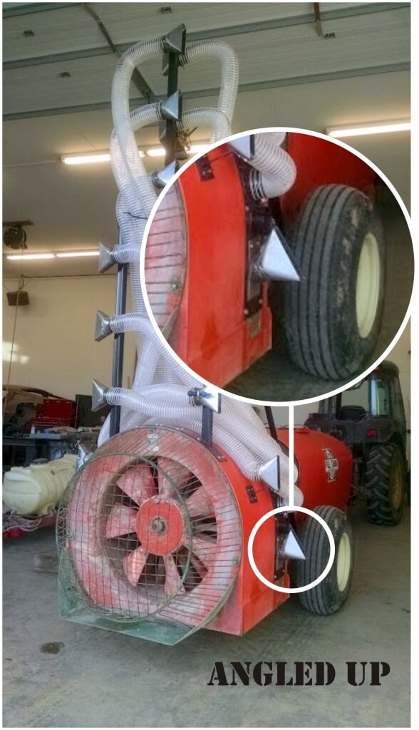
The top two nozzles are capped in this orchard (targeting 10′ and below). It’s very evident that the top two nozzles are not in use.
It turned out Steve, like many growers, also had a knack for metal working. Displeased with his Rears sprayer’s performance, he told me he’d replaced his classic radial air outlet and curved boom with a ducted tower assembly, very much like the H.S.S. sprayer had just been introduced to North America.
I asked if he would share his story and a few photos of how he did it and he didn’t disappoint! What follows is a photo journal of how he designed and built his new sprayer. He wrote:
“Sorry it’s taken me so long to get back to you. Spring is like a tornado and there’s just no time to get things done! Here’s a quick/not so quick rundown of the process:“
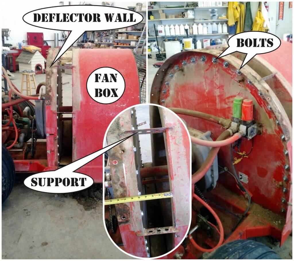
1 – I started by cutting the horizontal supports that attach the fan box to the front deflector wall. I plugged all the old holes with nuts and bolts to keep the air going where I wanted it.
Fan box cut away from deflector wall. Holes filled with bolts.
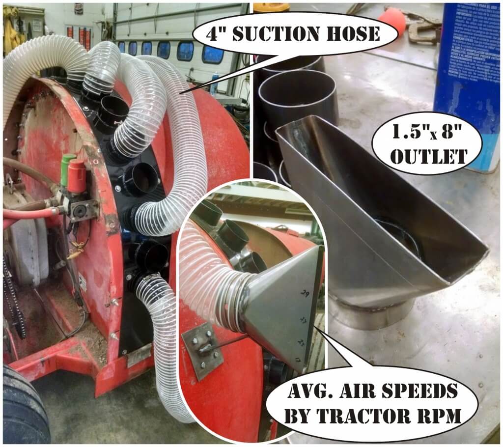
2- I then got a 10″ wide sheet of 16 ga cold-rolled steel from a local HVAC guy. I marked out where I wanted to attach it, drilled and tapped the holes, and attached using only stainless hardware. I marked out for a total of 8 holes per side evenly spaced, and drilled them out with a 4” hole saw. I then cut 3″ long sections of 4″ diameter thin-wall pipe (about 0.125” thick) and welded them flush with the inside.
Welded pipe outlets for air.
3 – I had several conversations with the local HVAC guy about turning vanes, nozzles, cubic feet/min. and wind speeds. The reason I decided to use hose after all these conversations is because there are no 90° angle turns. Those turns during testing severely decreased wind speeds because of the turbulence it caused. The hose is standard 4″ suction hose for woodworking chip/dust collection. Together, we came up with a 1.5” x 8” outlet to use. The numbers written on the outlet are average wind speed with 10 feet of hose attached at the desired tractor rpm’s.
Commercial woodshop hose and air outlets.
4 – Initially I was set on having the same distance of hose for each outlet, like headers for an internal combustion engine. I let that go since volume matters so much more in this situation and there is no “real” back pressure pressure to be concerned about. This was the initial drawing:
Early sketch of equal hose lengths and positions.
5 – My measured dimensions showed the rectangular tower frame would fit through my tightest V-trellis, but only if I drove 0.5 mph and who is going to do that!? So, I needed to rethink it, break it down, and redo it. I decided on a partial, center-mast design.
Original tower frame would not clear the V-trellis. A center-mast solved the issue.The top of the mast can be removed and the hoses disconnected and just left to hang. This allows me to hit 12′ tall V-trellis easily, as well as 14′ vertical trees all the way to the top.
6 – After putting everything together I realized the air volume wasn’t always balanced across the each outlet. This was because the bend in the hose was too sharp and too close to the outlet. This REALLY MATTERS because if the air volume is too “heavy” on one side of the outlet, it doesn’t capture and carry the spray consistently. I corrected it by attaching support rods to increase distance between bends and outlets to about 18”.
Gradual angles on hose prevented uneven air from the outlets.
7 – On the painted, final design, you might notice lowest nozzle is angled. This is because I’ve noticed that foliar applications don’t often hit the lowest branches. I angled one outlet upwards to correct this. I notice in your article on the H.S.S. sprayer that the Woolly Apple Aphid nozzle does the same thing. I feel like I need to meet these people; we have incredibly similar ideas!
Lowest nozzle and air outlet angled up to better hit lowest branches.
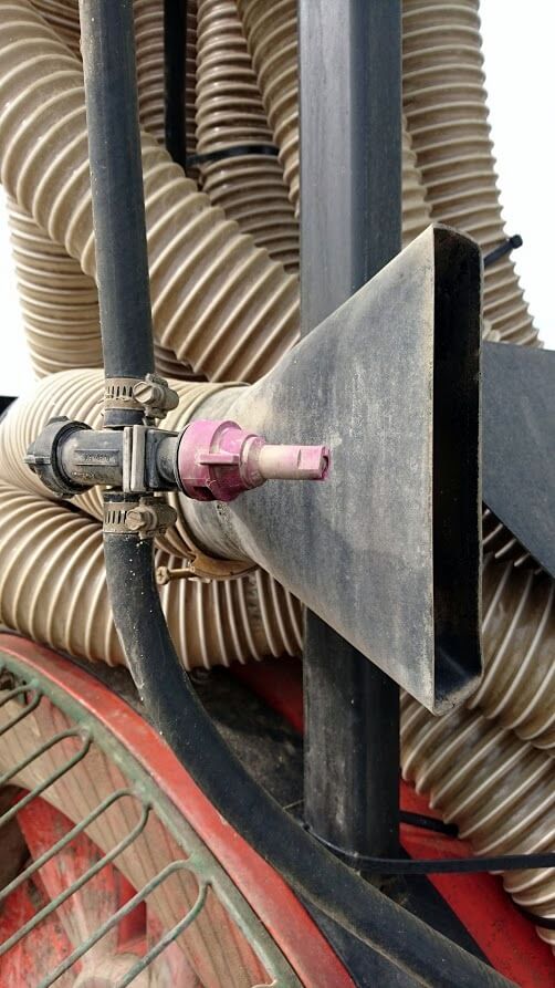
8 – I used TeeJet’s ¼ turn AIC air-induction flat fan nozzles. They’re molded into the cap, so they are always oriented the right way. I set the nozzle bodies outside the air outlets to reduce turbulence in the airflow. It also makes servicing cleaner and easier. I also ended up adding some shielding around the lower nozzles just in case someone loses focus and runs into something.
Shields prevent physical impacts to AIC (air induction) nozzles. Coverage map was created for 55 gpa in a 6’x14′ vertical planting.Close up of nozzle location versus air outlet.
I asked Steve to stay in touch and let me know how his spraying season goes with the new sprayer. I’ll add to this article as he checks in and lets us know how the sprayer holds up and what changes, if any, he wants to make in the future.
July 2016 Update
As promised, I checked in with Steve to see how the sprayer was holding up. Here’s what he had to say:
“It’s awesome. Works fantastic. Very effective in windy weather without having to worry about drift. Also, it works perfectly for sunburn protectants because of how directed the application can be. It has held up well considering how many acres its gone through this year.”
Of course, there are always a few hiccups. I’ll interject here to suggest that what Steve is about to note about thinning is not a reflection of his design. I believe many orchardists experience the same difficulties with their conventional towers, too. Steve continued:
“A few downsides I’ve noticed throughout the season: For blossom thinning (lime sulfur), gallonage is critical to get the stamen of the flower burned sufficiently to prevent fertilization. Even when spraying ~100 gallons per acre with this sprayer, it wasn’t enough to effectively blossom-thin the fruit. Part of this may be because I’m now distributing the spray evenly through the entire canopy, rather than spraying up through the canopy below. Another downside is the droplets’ tendency to accumulate in the lower portions of the tree (since every droplet doesn’t hit foliage), and over-apply in those areas. My Sevin/NAA application this year definitely prove this theory as my lower branches were over-thinned.”
So, what’s the final word on this cool sprayer mod?
“Overall, it’s great, and with a few tweaks this winter will be even better.“
When I had to replace a pump on a small scale sprayer, I had a lot of questions about how they worked, their capacities, hose sizes, mounting solutions and fittings. I turned to the Pentair Hypro Shurflo catalog and found a very helpful guide on pages 2 – 10. This article summarizes the steps recommended in the catalog.
Select Pump Style
Sprayer pumps can be divided into two categories: Positive Displacement Pumps and Non-Positive Displacement Pumps.
Positive Displacement Pumps
These include Roller, Diaphragm and Piston pumps. They are self-priming and traditionally operate at high pressures. Flow from these pumps is directly proportional to the pump speed, which is why they require a relief valve and bypass line between the pump outlet and the nozzle shut-off valve.
Roller pumps : This is the most popular pump with farmers world-wide. The seal and roller materials should be selected based on their compatibilities with the pesticides.
Diaphragm pumps : These compact pumps are popular for use with abrasive and corrosive pesticides. Their oil-filled piston chambers protect the pump materials.
Piston pumps : Similar to car engines, these pumps are relatively low-flow and high-pressure and suited for use with handguns sprayers. The piston cup materials should be selected based on their compatibilities with the pesticides.
Non-Positive Displacement Pumps
These include Turbine (or Transfer) and Centrifugal pumps. They must be primed and traditionally operate at low to medium pressures, although there are models available that can go up to 190 psi. Flow from these durable pumps comes from a rotating impeller that feeds liquid through the lines instead of pumping “per stroke”. Therefore, if the outlet is closed for brief periods, the impeller spins harmlessly, so a relief valve is not needed.
Determine PTO Pump Drive
When selecting a pump, you must specify the shaft rotation. Hypro suggests two steps for determining the required rotation:
Eyes on the End: Face the rotating Power Take-Off (PTO) and determine if it is spinning clockwise (CW) or counter-clockwise (CCW).
Opposites Attract: The pump must rotate opposite to the PTO. For example, if the PTO rotates CW, then the pump must rotate CCW and vice versa.
You should also be aware of your tractors’ horse power, and in order to determine the size of pump shaft, you should know the spline dimensions (e.g. 1-3/8″ (6 spline) pto shaft or 1-3/8″ 21-spline pto shaft).
Determine Pressure and Flow Requirements
In order to size the pump, you have to know the sprayer settings, such as intended application rate, average ground speed, agitation requirements, etc. Most can be calculated form the following formulae (provided in US and Metric units):
Calculating Agitation Requirements
Liquids :
Tank Volume (US gal.) × 0.05 = Agitation Requirement (gpm) Tank Volume (L) × 0.05 = Agitation Requirement (L/min.)
Wettable Powders and Flowables
Tank Volume (US gal.) × 0.125 = Agitation Requirement (gpm) Tank Volume (L) × 0.125 = Agitation Requirement (L/min.)
If the sprayer has a hydraulic agitation system equipped with a jet, it multiplies the agitation output without the need for additional flow. For example, it might have a 1 gpm input flow and boost it to a 10 gpm output. This savings should be accounted for:
Therefore, if you calculate a 60 gpm requirement for agitation, and have a jet that boosts the output 3:1:
60 gpm x (1 / 3) = 20 (gpm)
Calculating Nozzle Requirements
Once the agitation requirements are accounted for, you have to account for nozzles. The calculations are a little different for each sprayer, but they amount to the same thing – Total flow in US Gallons per minute or Litres per minute. Here is the calculation for a boom sprayer. For an airblast sprayer, assuming you are spraying every row, substitute “Row Spacing” for “Boom width”.
Total Flow Requirement (gpm) = [Output (gpa) x Ground Speed (mph) × Boom width (ft)] ÷ 495
Total Flow Requirement (L/min.) = [Output (L/ha) x Ground Speed (km/h) × Boom width (m)] ÷ 600
When the flow requirement for agitation and the flow requirement for the nozzles have been calculated, they are added together. It is important not to under-size the pump, so always factor in an extra 20% to compensate for changes in performance (such as pump wear and slower ground speeds) and restrictions in the plumbing systems that can cause pressure drops between the pump and nozzles, as follows:
Finally, be sure to account for any other flow requirements, such as tank rinsing nozzles and hose length/diameter (which causes pressure drops), and have some idea how you want to place the pump relative to the tractor and sprayer. If you prepare all this information, you can quickly and easily discuss your options with the retailer and select the pump that best suits your needs.
For more information on various types of pumps, check out this article by Dr. Bob Wolf:
A properly-sized pump should produce more flow than is needed and work in conjunction with the atomizers to regulate that flow. Typical to high pressure pumps, a piston relief valve (aka regulator) should maintain the desired system pressure through the normal speed range of the sprayer, regardless of the number of booms (or boom-sections) that are on or off. This is achieved by balancing the sprayer pressure against the relief valve spring, which must move freely across a range of flows.
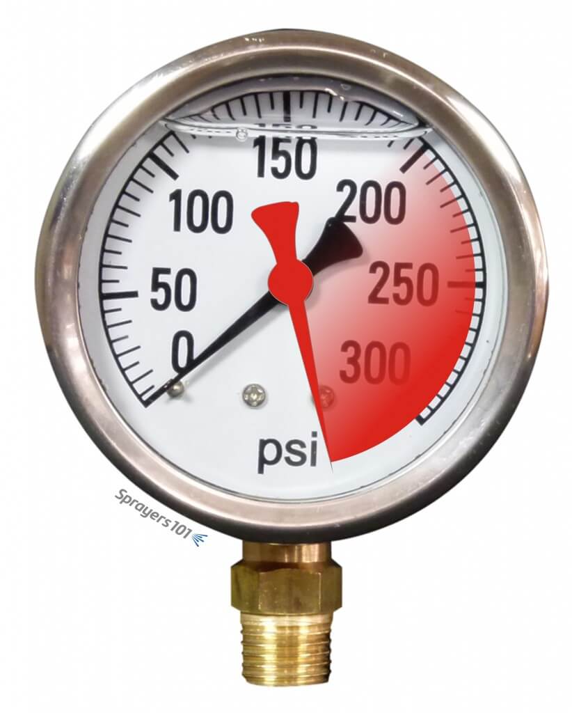
But what does it mean when the pressure gauge briefly spikes off-scale when boom are turned on or off? This is bad for the gauge and will eventually cause it to fail. Quite often, pressure spikes are an indication of one of two things:
A dirty or stuck valve
An inappropriate spring size
A pressure gauge spiking beyond its range.
Relief valve maintenance
Sometimes, pressure spikes indicate a need for valve cleaning and maintenance.
The regulator spring cavity may be packed with dirt, which limits valve travel. Clean the housing and spring, and then lubricate and adjust.
The regulator may be partially seized or sticky. If the regulator piston and cylinder bores are caked with spray they will ‘hold’ the valve until the pressure/spring balance overcomes the friction.
Sometimes valve, and/or the valve guide pin are seized. Disassemble them, clean all sliding surfaces, then lubricate and adjust.
Valve/seat wear may have created a leak. You may have already tightened the spring to compensate, but this loads the spring past the pressure balance point you want to spray at. This means that when the booms are shut off, the pressure increases until it reaches the ‘new’ spring balance point. Repair (or replace) the regulator, then lubricate and adjust. Be aware that any leak (external or internal) can contribute to this condition and tightening the spring isn’t the solution.
The spring may be damaged (e.g. bent, corroded, etc.). Replace the spring, lubricate and adjust.
Note: Be sure to read the operator’s manual before you do anything. You should understand your sprayer’s design before you perform any maintenance, adjustments or calibration.
Spring size
Sometimes, the relief valve may be mechanically sound, but the spring may not be sized to match a reduced operating pressure. Relief valve springs match the maximum pressure range of the pump. Sprayers operated at lower pressure may be unable to compress the spring. This is common when people switch from disc-core nozzles operated at higher pressure to molded nozzles operated at lower pressure.
This would manifest when one boom is shut off for single-boom operation; there may not be enough pressure to open the bypass. As a result, flow increases over the remaining boom.
Recognizing this problem, some operators have teed-in a second relief valve capable of finer adjustments at lower pressures. Make sure you know what you’re doing if you’re considering this option.
Technically, a spring can either be too weak, or too heavy:
The spring may be too weak for the pressure being used (i.e. any adjustment bottoms out). In order to obtain sufficient pressure the operator tightens the spring until it is virtually collapsed, essentially creating a fixed orifice. When the booms are closed the ‘fixed orifice’ doesn’t compensate and pressure rises to force the increased flow through that small orifice.
If the spring is too heavy for the pressure being used (any adjustment barely touches the spring when pump is turned off). In this case, the pressure being used will not deflect the spring, so the operator closes the regulator until the ‘fixed orifice’ creates sufficient restriction to flow to achieve the desired pressure. When the booms are closed the ‘fixed orifice’ doesn’t compensate and pressure rises to force the increased flow through, or until the spring begins to deflect.
In either situation the spring must be sized so it is in the centre-third of its flex range (i.e. rest state > fully collapsed) at the desired pressure. You can buy springs from the sprayer dealer or hardware supply. Try to maintain original length and diameter of the coil, while varying the diameter of the wire.
Engineering
In some cases, it is not a matter of valve maintenance, or spring size, but poor engineering. Consider the following:
The valve supply and return may be too small for the pump flow. Consult hose and fitting catalogs for flow capacities and lengths. Re-size the hoses and fittings appropriately, and then adjust the regulator.
There may be kinks or sharp bends in in the supply and return lines. Re-route the hoses and/or fittings to avoid kinks and sharp bends, and then adjust the regulator.
The relief valve may be too small for the pump flow. Consult a regulator catalog for flow capacities and replace the regulator with an appropriate size. Calibrate the regulator spring and adjust.
Relief valves have a ‘cracking’ pressure (that’s when the valve just starts to open). Well-designed regulators have small pressure changes from ‘cracking’ to full flow. That information is in their catalogs. Poorly designed regulators have large pressure changes between these two ratings and these regulators should be avoided.
The pump may be too big for system. This often happens when sprayers are upgraded and pumps are replaced. Consult the catalogs and reduce pump size or speed, or increase the sizes of the hoses, fittings and regulator.
There may be a hydraulic agitator jet on the regulator ‘tank’ line. An agitator jet applies considerable back pressure to a system, and when booms are closed the increased flow causes more than a linear increase in pressure.
Broadly, the sprayer system as a whole may be poorly engineered. Inspect and draw a flow path of the sprayer system. Examine where everything is going (or not going). Is it possible someone made changes that the manufacturer did not intend? Consult the manufacturer if you are uncertain. Sometimes, it will have to be re-engineered, which may require expert consultation.
Note: Your pressure gauge can tell you a lot more than your operating pressure – it can indicate a problem with your regulator, pump, lines or overall sprayer engineering. Don’t ignore it – address it.
Thanks to Murray Thiessen, Consulting Agricultural Mechanic, for his contribution to this article.
This article was co-written with Murray Thiessen, Consulting Agricultural Mechanic.
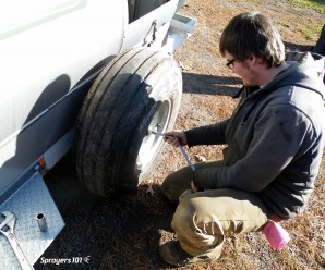
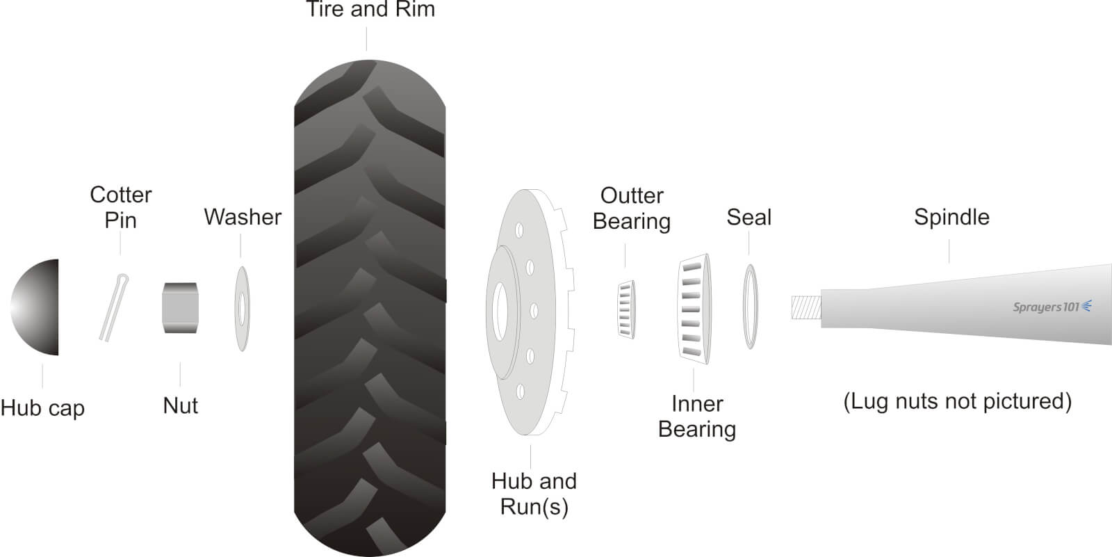
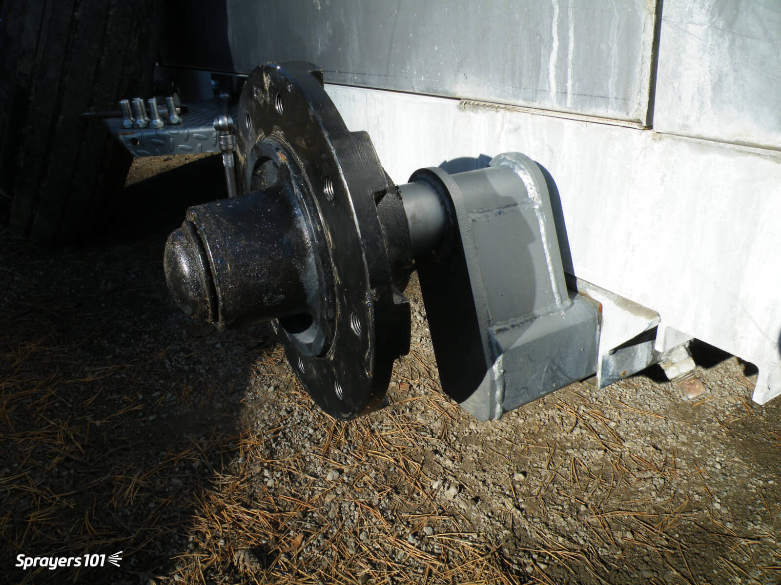
Sprayer wheel assemblies should be cleaned and inspected as part of regular annual maintenance. Wheel bearing maintenance before long-term storage may prevent water from corroding the bearings. The exploded diagram details the parts found in a typical trailed air-assist sprayer wheel assembly.
Exploded diagram of typical airblast sprayer wheel assembly.
The following procedure was performed on a 2012 Durand-Wayland sprayer by Mr. Murray Thiessen, Consulting Agricultural Mechanic and renowned “Sprayer Whisperer”. The steps are applicable to most sprayer makes and models. The entire process should take approximately half-an-hour per wheel.
Step 1
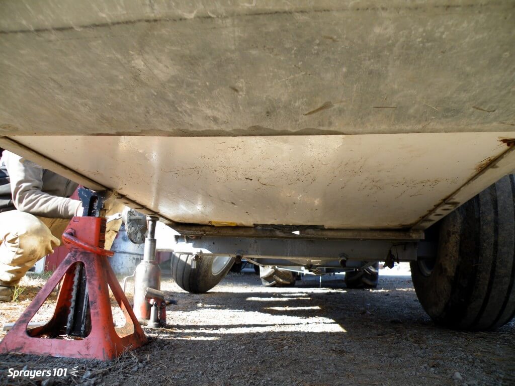
Empty the sprayer and park it in a well-lit, level spot. Un-hitch the tractor and raise one side of the sprayer using a bottle or floor jack to clear the wheel. Secure the sprayer with a jack stand.
Raise with one jack, secure with another.
Step 2
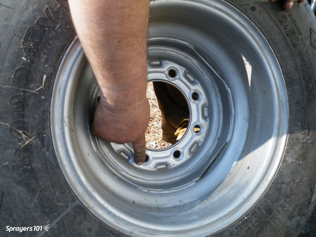
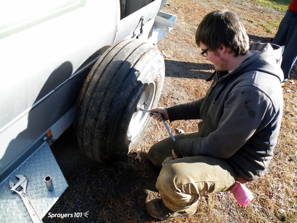
Remove the lug nuts and take the wheel off the hub. Do not remove the wheel and hub together because it is heavy and you might bang the delicate seal on the spindle. Check the wheel rim for signs of corrosion or distortion (often caused by either loose or over-tightened lug nuts). Check the tread for wear or cuts and check the tire pressure.
Remove the lug nuts and take the wheel off the hub.
Step 3
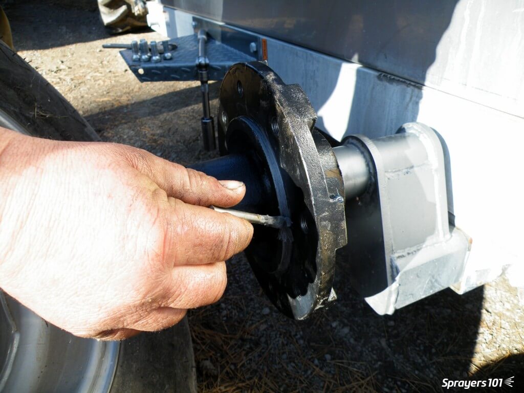
Remove the hub cap and pull out the cotter pin. Then remove the nut and washer that hold the hub on the spindle. Put all the small parts in a plastic container with some de-greaser (e.g. Varsol) to clean the parts and keep them from getting lost.
Remove the nut and washer that hold the hub on the spindle.
Step 4
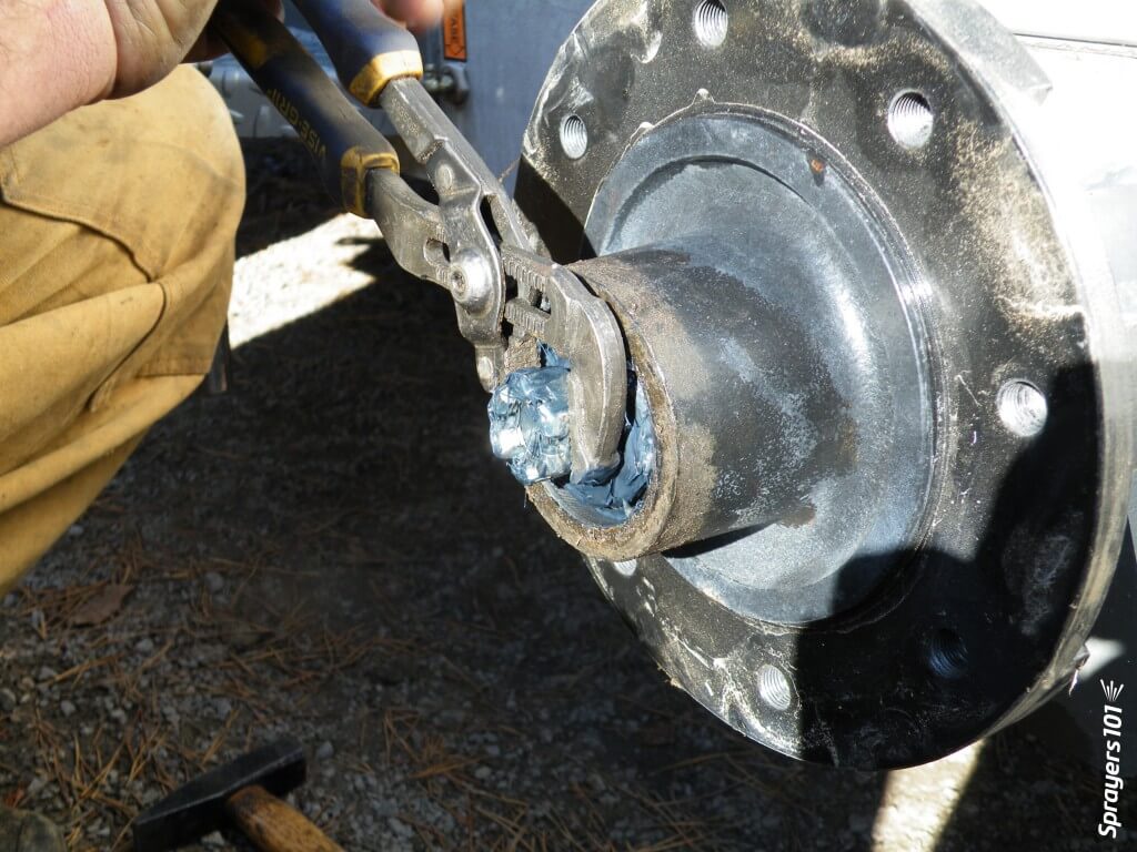
Knock out the seal and hub bearing and put them in the plastic container. Unless it is damaged, there should be no need to remove the bearing cup (or race) from the hub. The seal is designed to keep dirt out of the assembly, not to keep grease from escaping. Be sure to note which way it is facing. The seal is often ruined during disassembly; have a replacement on hand.
Knock out the seal and hub bearing.
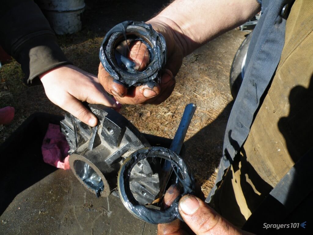
Step 5
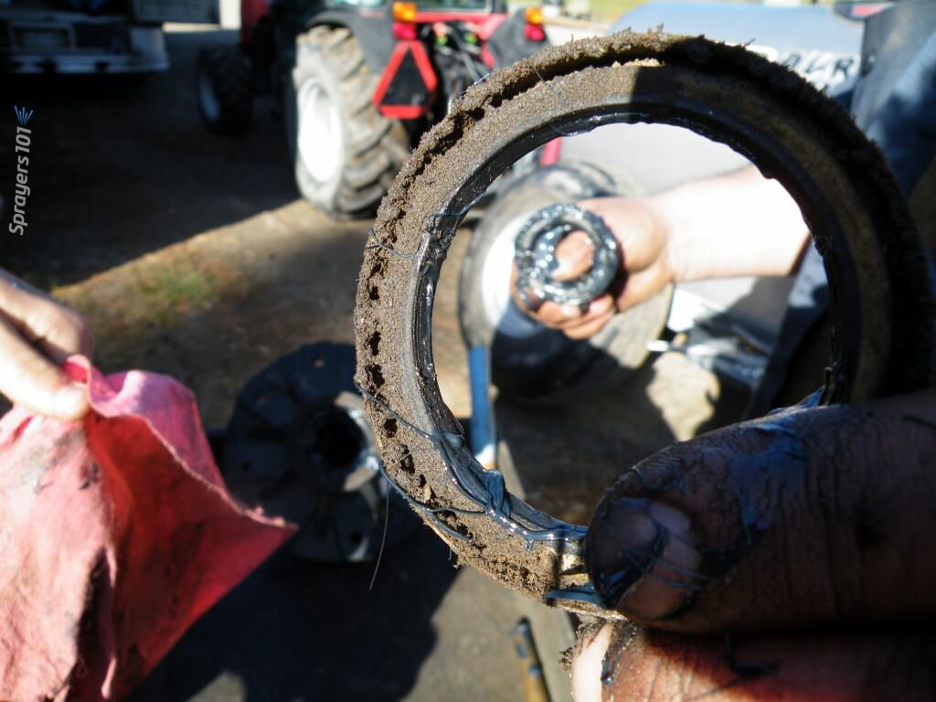
Clean the old grease out of the hub. This hub has too much and it has filled much of the air space (or cavity) within the hub. That air space is provided so grease is not forced out as the hub heats up, and so dirt is not pulled in as the hub cools. Note the colour of the grease – if it is black and stains your hands, it has burned because too much grease has caused overheating. Look for evidence of dirt or water in the bearing, which indicates seal failure.
Clean the old grease out of the hub.
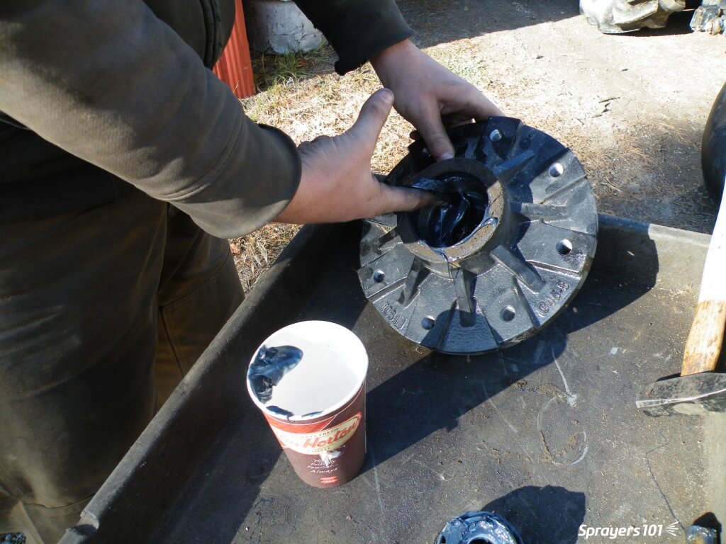
Step 6
Wipe dirt from the spindle. Never pressure-wash wheels when they are on the spindles because the spray drives dirt and water past the seal and into the hub. Inspect the sealing surface of the spindle for damage or wear.
Wipe dirt from the spindle.
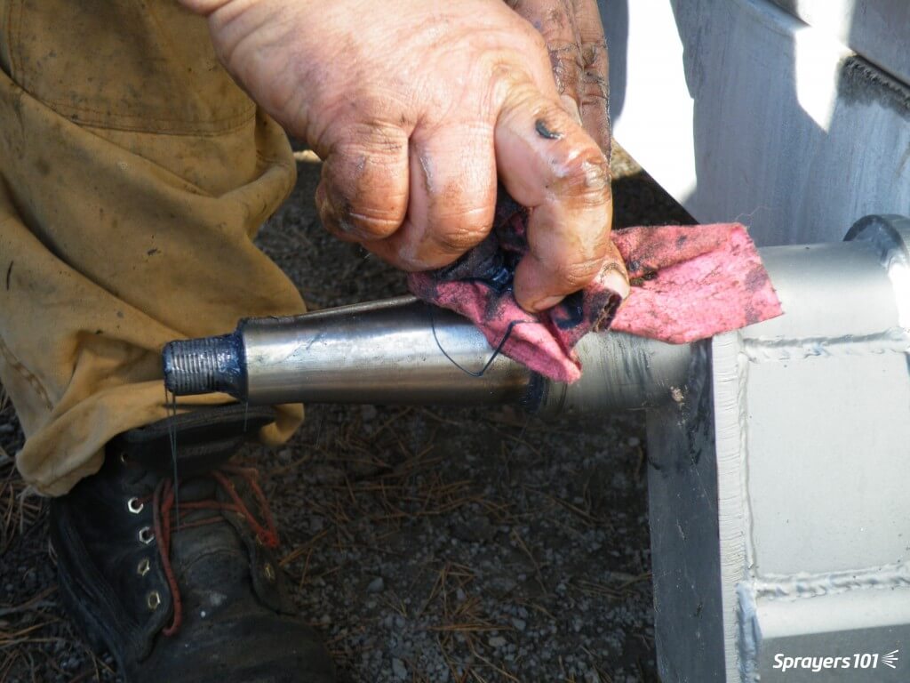
Step 7
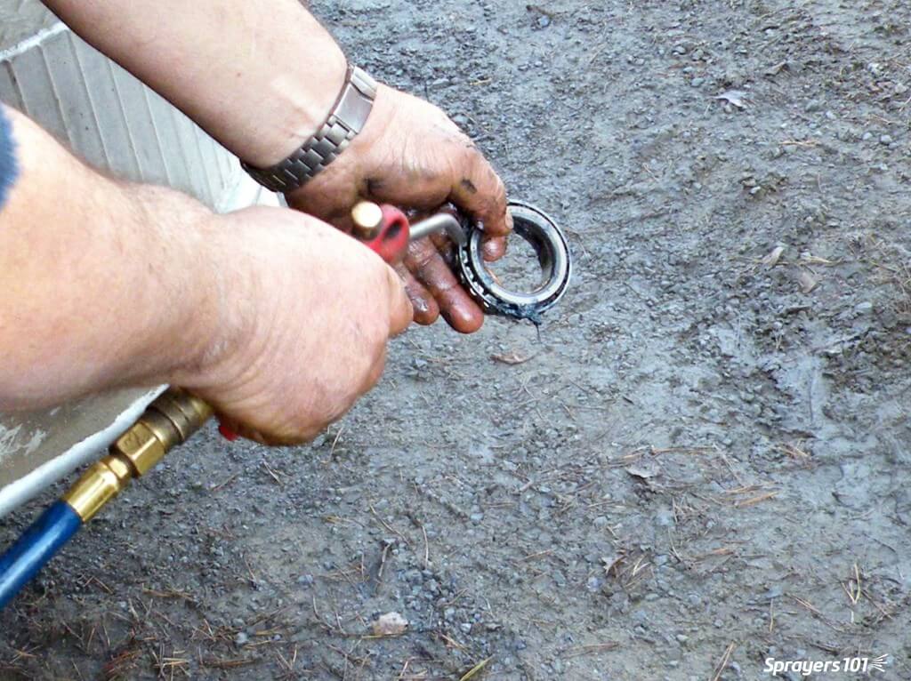
Clean the seal thoroughly. Seals are easily damaged and may need replacement.
Clean the seal thoroughly.
Step 8
Clean the hub bearing. Compressed air is a good way to get all the old grease out, but do not spin the bearing with the air.
Clean the hub bearing.
Step 9
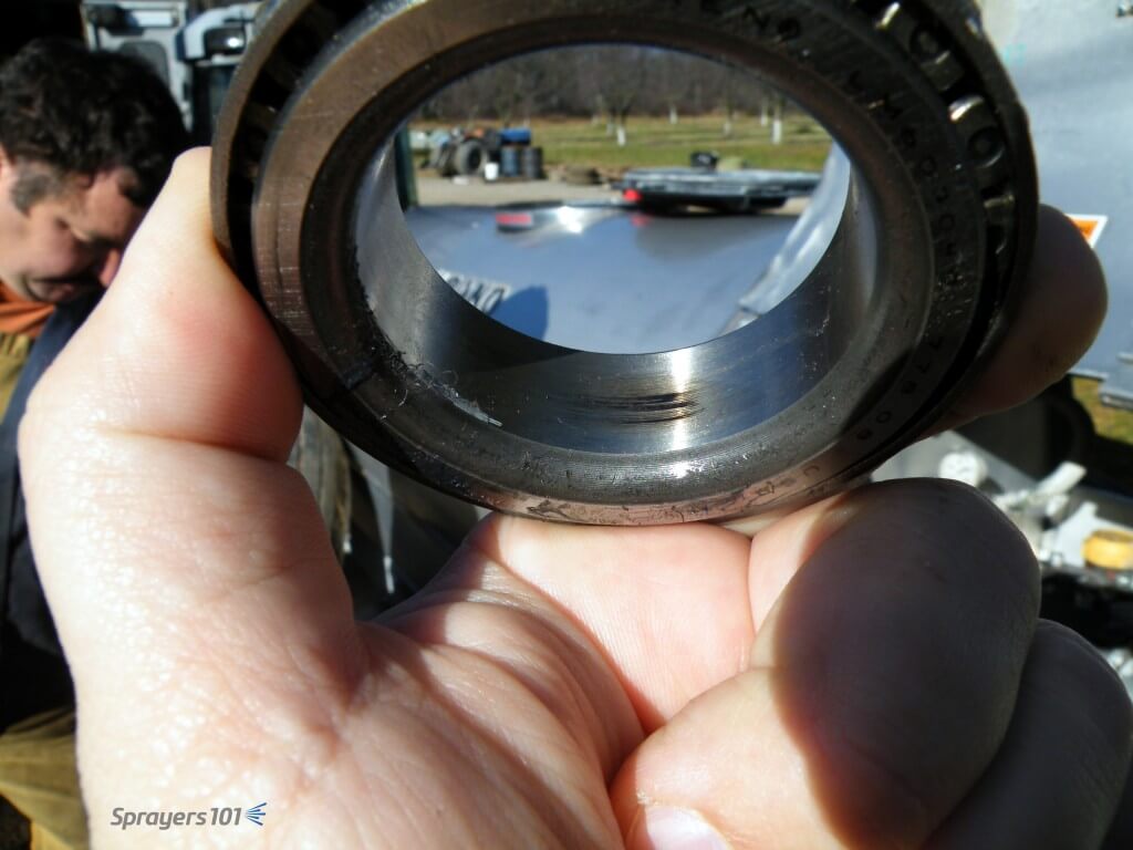
Look for scratching, pitting or blue metal (indicating heat). This scorch mark indicates the bearing was moving on the spindle, and the friction created heat. Agricultural wheel bearings do not fit tight to the spindles. If there is too much clearance, the bearing race will turn on the spindle where it is not supposed to.
Look for scratching, pitting or blue metal (indicating heat).
Step 10
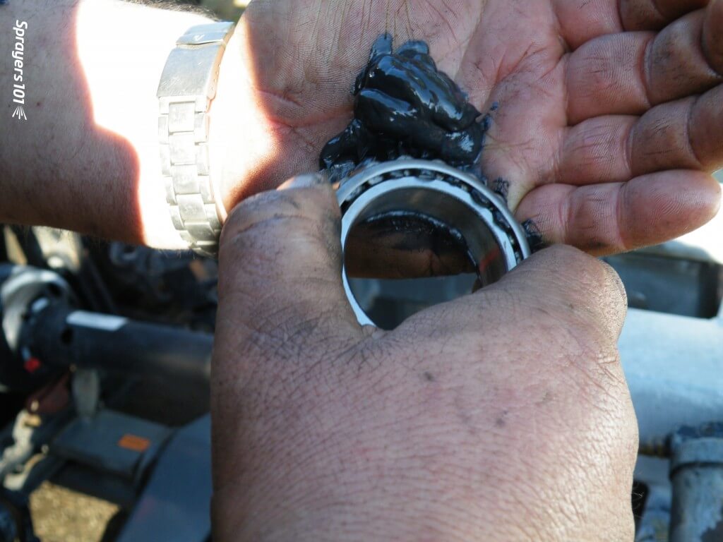
Repack the bearings, reassemble the hub and re-grease the hub. Bearings should only be ~40% full. Too much grease creates heat and does not let the bearing roll properly. Too little increases friction. No matter which grease you choose to use, never combine greases; they may not be chemically compatible.
Re-pack and reassemble.
Step 11
Mount the hub tightly on the spindle. Replace the washer, cotter pin, nut and cap. There is no need to bend the arms of a cotter pin all the way back – it weakens the metal. Just bend one arm to 90° and cut off the excess. Use anti-seize on the wheel pilot to make the rim easier to remove next time.
Mount the hub tightly on the spindle.Some airblast sprayers (such as this Durand-Wayland) have wheel assemblies that can be rotated to four different positions in the chassis. This will raise or lower the sprayer to better align it with the tractor hitch and PTO shaft.
Step 12
Replace the wheel and rim. Do not grease the lug nuts or they might loosen. Over- or under-torqueing lug nuts can cause damage. Look in the manual for your correct torque and consider using a torque wrench. Tighten the nuts in a star-shaped pattern – not sequentially.