- Measure canopy and planting layout to calculate application rates and position booms for complete coverage.
- View targets from the droplet perspective; choose droplet size and pressure to reach abaxial leaf surfaces without excessive run-off.
- Calibrate sprayer: verify pressure gauge, nozzle condition and orientation, boom check valves, and actual travel speed.
- Test and iterate with water sensitive paper, adjust nozzles or twinjet configurations, then recalculate tank mixes and monitor crop response.
This text was generated by OpenAI GPT 5 Mini
In April 2025 we visited Cedarline Greenhouses to assess their spraying methods. Our hosts invited us to examine their practices and then graciously agreed to let us share the process (and the results) so others could learn from the experience. Every greenhouse is different, but with a little imagination the process we used should translate to most operations. I want to be clear that this operation was already doing a good job before we showed up. It’s just easier for someone from the outside to scrutinize and find little things that might need tweaking. Let’s go through the steps we took that day.
1. Measure the crop canopy and the planting architecture
The objective of any spray application is to achieve sufficient coverage of the target with as little waste as possible. Achieving this goal means understanding the interaction between the sprayer, the spray droplets, and the crop canopy.
Start by measuring the the planting architecture. These values allow us to calculate application rates and to calibrate the sprayer. Cedarline is a 16-acre pepper operation. The crops are strung vertically in double rows for a total canopy depth of about 1 m, leaving roughly 0.5 m clearance in the alleys. Spraying takes place while the crop is between 1.5 and 3.5 m high. Each row is 102 m long.

2. Consider the target from the droplet’s perspective
Stand between the rows and face the canopy. Where is your spray target relative to the nozzle? Is it in line-of-sight, or are there parts of the canopy in the way? In this case, our primary targets are sucking insects found predominately on the under-side (abaxial) surface of the leaves, and not the waxier, above-side (adaxial) faces.
As we look through the double row, we see the adaxial sides face out towards the alleys, and the abaxial sides face the canopy interior. Bad luck. But, as we peer through that first row to the second row, we can see the abaxial sides of those leaves. So, perhaps enough of the spray can penetrate past the first row to deposit on the abaxial surfaces of the far row? This is a tricky plan because of the physics of droplet behaviour.

We know that coarser droplets move ballistically (e.g. like cannon balls), so perhaps they could span the distance from the first row to the next. But they are prone to bouncing and running off surfaces, which means they’d likely drench the waxy adaxial side of the first row before any get to the abaxial side of the far row… and those that do might not stick to the target.
On the other hand, finer droplets are less prone to run off, so they’re much better at sticking to hard-to-wet surfaces like peppers and waxy leaves. Additionally, thanks to the cubic relationship between droplet size and volume, the smaller the average droplet size, the more droplets we have working for us. However, finer droplets don’t have a lot of mass, so they move erratically, and they are prone to evaporation. Maybe they won’t reach deeply enough into the row.
Fortunately, greenhouses are humid places, so finer droplets don’t evaporate quickly. Plus, greenhouses tend to spray at relatively high pressure (200 psi or more), which imparts momentum to finer droplets. Also, when enough tiny particles move in a single direction, they create air currents – essentially a light wind. This side-effect is sometimes enough to move leaves, creating holes in the canopy and exposing the abaxial sides of leaves as they twist. So, there’s hope. Now let’s look at the sprayer.
3. Examine the sprayer and the nozzles
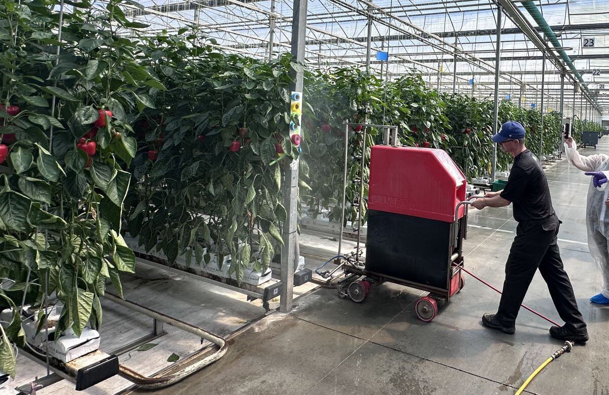
Cedarline uses semi-automatic “robot trees” (Wanjet model S55). This sprayer has a vertical, 2 m high boom with nozzle bodies spaced every 25 cm. When the crop grows higher than the boom, an extension is added to bring it to 4 m. Flange wheels allow the sprayer to ride the hot water pipes between the rows like a train on rails at a rate of 60 m/min.

The sprayer is manually placed in the row. Then it trundles along, spraying one side, until it reaches the end of the row. Then the vertical boom turns to spray the other side on the return trip, where it is retrieved and placed in the next row. The sprayer is fed from a portable tender unit via a 180 m auto-reeled hose at 200 psi. The question is, does this all work the way we assume?

4. Calibrating the sprayer
4a. Pressure
We started with pressure. If pressure is the force that causes a specific volume of spray mix to exit the nozzles at a specific rate and produces a specific droplet size and spray geometry (e.g. a cone or a fan), then it’s very important to know that it’s accurate.
Remove the gauge with a wrench (never turn it by the face) and test it against a known gauge. You can build a test apparatus very easily. Alternately if the gauge is showing wear, such as the needle not sitting on the zero pin, or it’s opaque, or leaking, maybe just replace it without testing.
In our case, we discovered the gauge was off by 20%. Where the standard gauge read 150 psi, the working gauge read ~120 psi. Plus, the scale of the gauge was far too high. Best practice is to use a gauge rated to about double the operating pressure. This gives better resolution, and a quick glance shows if the needle is pointing straight up.

I prefer a tender system like this over a central spray tank in a header house. In systems where there is a central tank and the sprayer hoses plug in at intervals, the degree of pressure-drop increases with distance from the source. If this is you, install a regulator on your sprayer and adjust it accordingly to hold the pressure constant. In this case, the distance the spray solution travels is always constant, so the pressure doesn’t change. Best practice in either case is to install a pressure gauge on the sprayer at the end (or top) of the boom so you can confirm the operating pressure is correct.
4b. Sprayer speed
We were told the sprayer was set to travel 60 m/minute, but is that true? Certain chemistries will deposit a slick coat on the hot water pipes and the flanged wheels can slip (especially as they wear). There was obvious damage to the rubber surface of two of the flanged wheels that might have affected travel speed. We should have checked, but we didn’t. Use a timer and confirm how long it takes for the sprayer to travel to the end of the row. Don’t include turn time. If it doesn’t match your expectation, then adjust the speed until you get what you want.
4c. Boom and nozzles
Next, we explored the boom and the nozzles. The first thing we saw was that their alignment was wrong. Flat fans in ¼ turn nozzle caps will self-align on the lug to ensure each spray fan does not physically impact it’s neighbours. However, the nozzle bodies themselves can sometimes turn on the threaded boom, and they need to be realigned. We did that before removing a few tips for inspection.

I asked when the nozzles were last replaced and was told the sprayer arrived pre-nozzled with TeeJet visiflo 8002’s. They had never been inspected, other than when they plugged, and their rates had never been confirmed. Upon inspection we found some were physically damaged. This doesn’t mean the nozzle orifice was compromised, but it instilled doubt. You don’t always see obvious damage but know that the orifice is delicate and very precise. As it wears it gets larger (increasing flow), but more insidiously it also changes shape, altering the size of the spray droplets, which we’ve established are critical to our spray strategy.

Best practice is to test nozzle outputs at a known pressure and replace them when they are 5% off the expected rate. Unless a nozzle gets physically damaged, replace them as a set so they wear as a set. When do they wear out? It depends on the nozzle material, the nature of what you’re spraying, the pressure and the amount of time they spend spraying. Here’s a link to an article that suggests several methods for testing nozzle output. Some are cheap and slow, others are fast and expensive, but they all work.
If that’s not appealing, you can mark your tank and see how many rows you should be spraying versus how many you’re actually spraying. Ultimately, given the relatively minor expense of new tips versus the trouble of calibrating them annually, it’s often simpler to replace them at intervals. In this case it’s worth noting that the first 2 m of boom operates all season, while the extension is only added later, so they won’t all wear at the same time.
We examined and then returned the original tips to the boom for the next part of the calibration. We noticed that the gaskets were stretched (crushed). This made it hard to put the nozzles back on, so they would also need replacing.
We turned on the boom to ensure we had everything back in the right place, and noticed that when we stopped spraying, the boom slowly emptied through the lowest nozzles. That meant expensive products were left to dribble out every time the boom stopped spraying, which is wasteful. It hinted that the check valves, which are built into the nozzle bodies, were no longer working. Ideally, once the boom pressure drops below ~15 psi, each check valve diaphragm closes to prevent leaks. It also ensures the boom remains primed for the next pass. We advised that they should be replaced and to ensure the new bodies have the correct thread size. European sprayers rarely have the same thread as North American, so compatibility can sometimes be an issue.
5. Evaluating spray coverage
This is an iterative process, which means we test, evaluate, make a single corrective change, and repeat until we (hopefully) see what we want. Water sensitive paper (WSP) is a terrific tool for this process, but it has a few caveats:
- It will react to any moisture, including a humid atmosphere, so handle it with gloves and don’t let it sit for too long.
- The WSP surface is only a surrogate for a plant surface. Deposits tend to spread more on leaves, vegetables and fruits, but will always be smaller on the papers. So, only compare papers to other papers and infer that the actual crop coverage is better.
- We really don’t know how much coverage is enough. It depends on pest pressure, product concentration and mode-of-action (e.g. contact or systemic). Generally, we like 10-15% of the surface covered with 85 deposits per cm2 on 80% of the targets. Sometimes it’s easier to imagine the pest on the paper – can it fit between the deposits?
5a. TeeJet visiflo 8002 at 200 psi
We started by establishing a baseline using their current nozzles and pressure. WSP was folded and clipped at the petiole so we could assess adaxial and abaxial surfaces. We placed them deep in the canopy so we were looking at the worst-case scenario, and then noted where we left them (use a ribbon or part of the greenhouse as a frame of reference or you’ll never find them again). We sprayed from one side, then examined them in situ, then sprayed from the other side so we could see the impact of cumulative coverage.

After spraying from both sides, we saw excessive coverage on adaxial surfaces and marginal coverage on abaxial. For those that have tools to digitally scan and assess WSP, it worked out to 31% coverage and 225 deposits/cm2 on the adaxial side, and 2% and 16 deposits/cm2 on the abaxial. In fact, the adaxial side was so saturated (>25% coverage) that I don’t trust the deposit counts because of overlaps, but there it is. This is when we brought out the nozzle manufacturer’s catalogue (which you can also find online). We found their nozzle and looked up the flow table, which shows the relationship between pressure, output rate and droplet size.

Those in greenhouses might find that their operating pressures are far higher than what is listed, but that’s no problem. Find the highest pressure and output rate listed in the table and call those “Known Output Rate” and “Known Pressure”. Now use the following calculation to extrapolate flow for a new pressure. It’s also worth knowing that higher pressure tends to mean a wider fan angle and finer spray droplets than are listed in the table:
Unknown Output Rate (gpm) = Known Output Rate (gpm) × (square root of New Pressure (psi) ÷ square root of Known Pressure (psi))
In this case, at 200 psi this nozzle should produce 0.45 gpm. If we go up one size from the yellow 02 tip to a larger blue 03 tip, we can produce a similar flow but using only 100 psi. This would put less strain on the system, but it would also make droplets larger, fewer and perhaps slower.
5b. TeeJet visiflo 8003 at 100 psi
We tried the 8003 at a lower pressure and saw that the deposits were obviously larger on the adaxial side, and not saturating, which is good. However, we saw insufficient deposit density on abaxial, which was a deal breaker.
5c. TeeJet visiflo 8003 at 200 psi
We left the blue 8003s and brought the pressure back up to 200 psi. Now the flow was increased to 0.67 gpm, and the droplets were finer, more plentiful and moved a lot faster. The adaxial surface went back to excessive coverage, but perhaps not as bad as with the 02s. The abaxial deposit density was improved, but still not sufficient. You can see the results of the three trials in the photo below. Go counter-clockwise from 1 (at bottom right) to 3 (at top).

5d. TeeJet twinjet TJ6011003 at 200 psi
It was time for a radical change. We replaced the single flat fan geometry with twinjet flat spray nozzles (TJ60-8003). We tried this because we’ve tried it in the past and it worked well. We retained a blue 03 rate, so we still produced 0.67 gpm at 200 psi. This nozzle also retained the 80° fan angle, but created two of them at 60° to one an other. This would change the spray trajectory, creating new opportunities for droplets to align with the targets. Perhaps most importantly, the twin fan nozzles would produce finer droplets than their single fan cousins, increasing the odds and perhaps and creating more “wind”.

We saw far less differential between abaxial and adaxial surfaces, with deposit density greatly improved on both surfaces. While the adaxial face showed larger deposit diameters, they were close enough to require close inspection to determine which side was which; Coverage was more uniform, with no drenches and no misses. By the numbers we saw 34% and 523 deposits/cm2 on the adaxial side (again, hard to trust the counts here because of overlaps arising from >25% coverage) and 19.5% and 400 deposits/cm2 on the abaxial. We had a winner.

It’s also worth noting that every time we sprayed, we observed the deposit on the fruit and leaves. None of the sprayer configurations caused run-off (e.g. drip points on the bottom of the fruit or tips of the leaves), which would suggest we were not using an excessive volume. Look closely at the following two pictures to see the beads of water and how they deposit. They look great.


We also watched to see if spray passed through the row into the next alley. A little puff here and there is fine, because it meant the spray was reaching the far side of the row. However, spray that blows through the row excessively is wasted becuase it misses the target row and ends up on the greenhouse floor.
Epilogue
We were pleased with the result of half-a-day’s effort. We left our hosts with some homework:
- Change the pressure gauge to one that is accurate and spans to 400 psi.
- Replace all nozzles and gaskets and ensure they are properly oriented.
- Time the sprayer to confirm travel speed is what they assumed.
- Using the known speed, pressure, and boom output, do the math to account for the fact that they would now be spraying a higher volume than they were. This will change how much product they put in the tank.
- Watch the crop closely to ensure these changes do not compromise crop protection.
Everyone learned a lot from our day together. Cedarline said they would calibrate their other sprayers using this process. They are even going to try a set of yellow 02 TwinJets to see if they can achieve sufficient coverage at their current pressure, which would mean they can continue to mix product at the same concentration. Those are pretty small orifices, guys, so watch out for plugged tips and good luck!
Hopefully this inspired you to look critically at your own operation and to follow these steps to calibrate and optimize your crop protection practices. Happy Spraying.
