Tag: field sprayer feature

  • Green-on-Green in Ontario: A Custom Operator’s Experience with See & Spray Premium

    Green-on-Green in Ontario: A Custom Operator’s Experience with See & Spray Premium

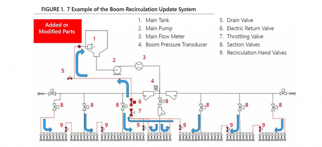
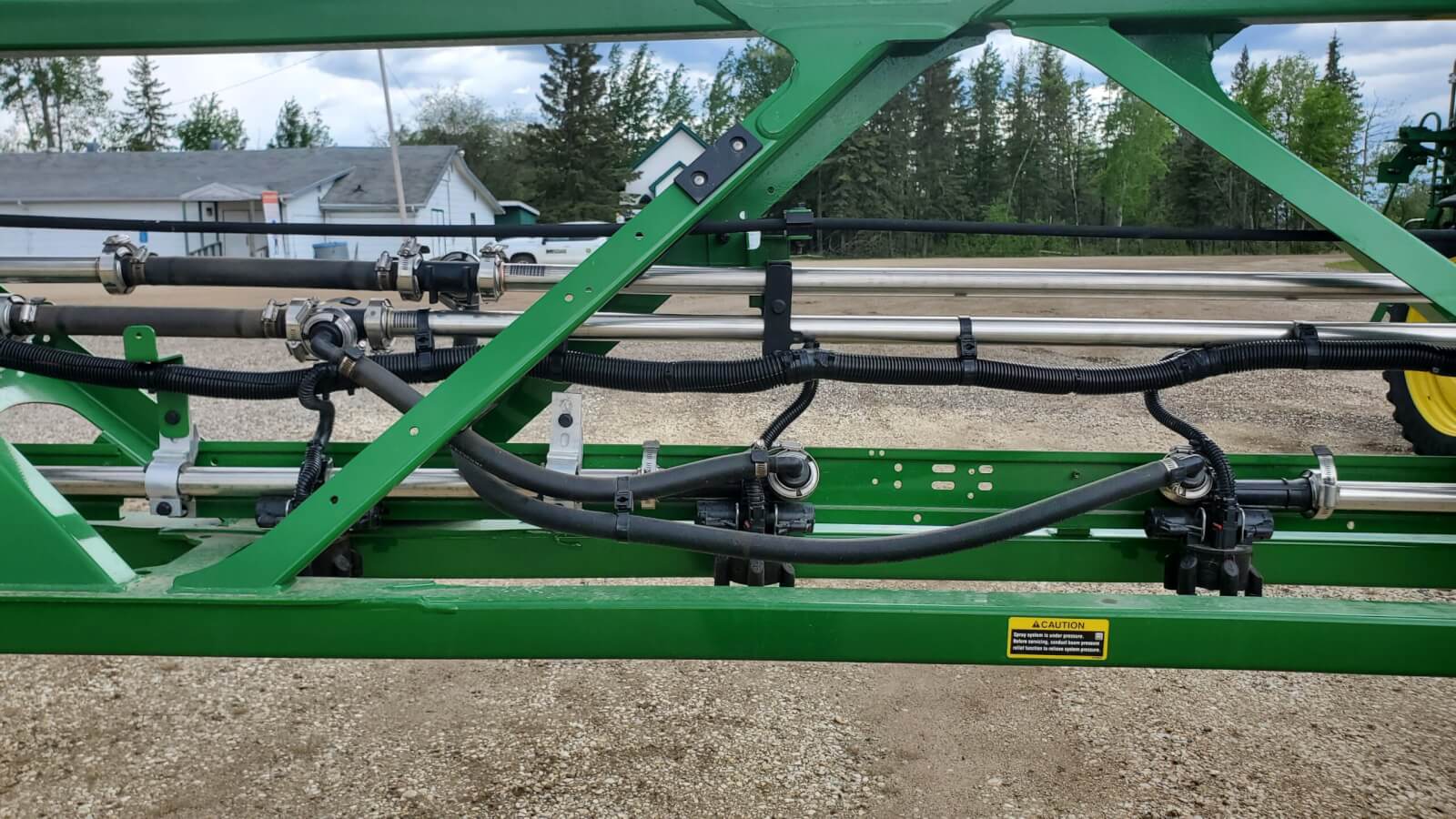
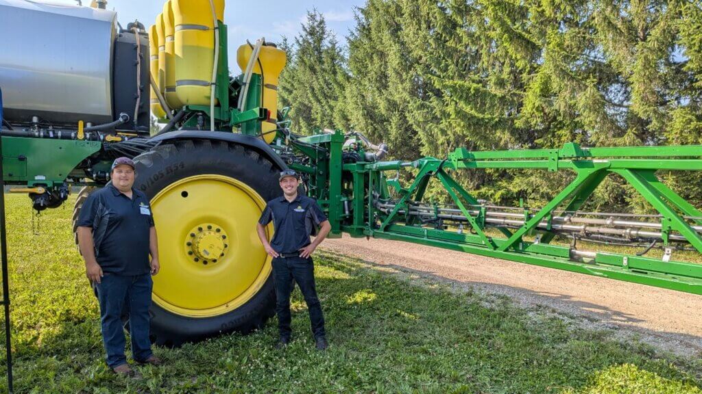
    In the summer of 2025, Todd Frey of Clean Field Services (Drayton, Ontario) and I participated in the Elora Weeds Tour. We discussed his new John Deere See & Spray Premium and the practical considerations for implementing green‑on‑green spraying in Ontario (Figure 1). With that first season squarely in the rearview mirror, I reached out to Todd to ask about his experience.

    To be clear, we had a lot of questions then and we still have questions now… but we’re optimistic. This article summarizes the original topics from the Weeds Tour, Todd’s 2025 learnings, and considerations for the year ahead.

    Figure 1 – JD See and Spray Premium at the 2025 Elora Weed Tour. Todd Frey (left) and Brendan Bishop

    Challenges Identified in 2025

    Label Language and MRL Constraints

    Optical spraying introduces uncertainties when interpreting pesticide labels written for broadcast applications. For example, an operator might elect to concentrate a herbicide beyond the common broadacre rate while technically adhering to the label. Depending on the active, this risks excessive residue levels that can cause crop replant issues. A few Canadian labels already address this grey area by specifying water-to-product ratios in addition to per‑hectare limits. Most do not.

    Australia’s experience offers a possible way forward: optical systems in Australia are commonly calibrated at 100 L/ha (~10 gal/ac), and labels specify whether they permit higher concentrations for spot and patch spraying. Additionally, most labels state the operator must revert to a conventional broadcast application when fields have more than 30% weed cover.

    Tendering and Mixing Logistics

    Estimating product and water needs is, perhaps, one of the most difficult operational challenges. Traditional field scouting cannot accurately predict how much spray solution an optical sprayer will apply. This leads to logistics issues, increased risk of unnecessary leftovers, and subsequent disposal/clean out problems.

    Nozzle Availability and Performance

    Nozzle choice is central to realizing the full benefit of precision application. Ideally, operators require low‑drift, narrow‑angle nozzles with an appropriate dynamic range (i.e. travel speed vs. flow rate) to spray small weeds efficiently. Perhaps it goes without saying that a stable boom is critical in this equation, but we’ll say it anyway. Nozzle options are currently limited and we’ve written about this subject in a previous article.

    Cost–Benefit Realities

    While herbicide savings are an obvious appeal, the actual economics are more nuanced. The See & Spray Premium model adds a $6/acre CDN fee for unsprayed acres, which can diminish savings in very clean fields. A fall broadcast herbicide application improves the success of spring green‑on‑green passes, but this added cost must be figured in. Of course, there are many other benefits to a fall burndown that shouldn’t be dismissed, and you can read about them here.

    On the other hand, perhaps good agronomy should be the motivating factor. Any savings from reduced broadcast spraying may allow operators to upgrade to more effective, higher‑value tank mixes, improving weed control and contributing to long‑term seedbank reduction. Regarding the later point, there have been recent studies that suggest using low sensitivity may adversely affect the seedbank.

    New Chemistry Possibilities

    It’s a stretch, but there could be a silver lining to increasing herbicide costs and resistance pressures: chemistries once considered too expensive for broadcast use could become economically viable for spot or patch applications. This would expand chemical options.

    The 2025 Experience

    Cost savings

    To evaluate performance under Ontario conditions, Todd conducted a structured trial on his own 125‑acre corn field. In 2024 the field received a fall application targeting annual grasses and broadleaf weeds. Todd’s intention was to leave perennial sow-thistle and Canada thistle for targeted control in the spring.

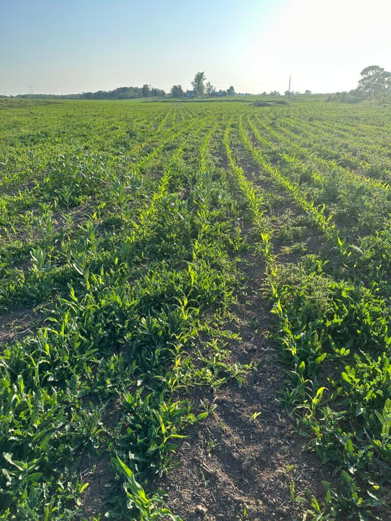
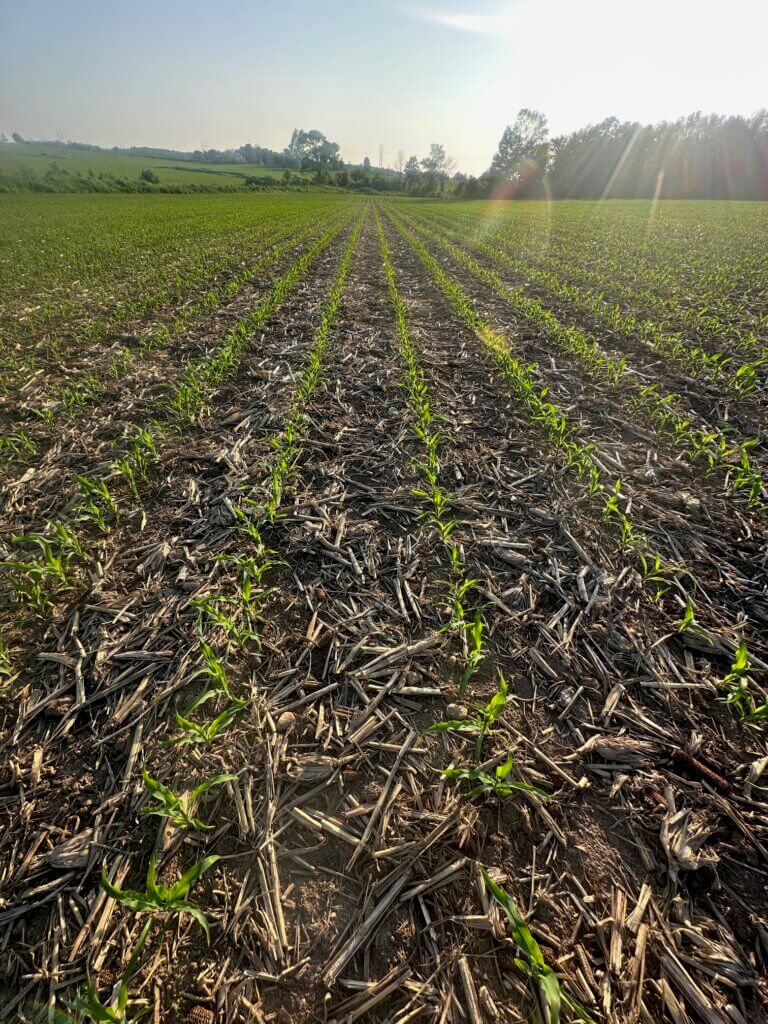
    He used the See & Spray Premium to apply Lontrel + glyphosate at 13 GPA. The John Deere Operations Center map (Figure 2) shows a distinct high‑pressure zone in red. This corresponds to 2–3 acres recently reclaimed for production —significantly weedier (Figure 3) than the remaining acreage (Figure 4). This work was performed using the Deere TSL8005 nozzle, with sensitivity set to 3 (medium) and buffers set to medium in both directions.

    Figure 2 – John Deere Operations Center weed pressure map
    Figure 3 – High weed pressure in the reclaimed section of the field
    Figure 4 – Low weed pressure in the majority of the field

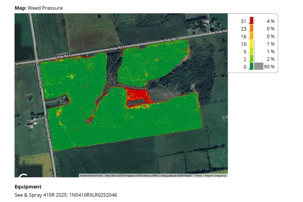
    Download a copy of the as‑applied data. You’ll see the See & Spray treated only 25.8% of the field. If Todd had broadcasted Lontrel at 65 mL/ac and charged his typical $14.50/ac it would have cost $4,139.36. However, even with his premium spot-spray rate of $17/ac and passing on the $6/ unsprayed acre, the total cost was $3,507.96. This represents a net savings of $631.40, and the surprise twist: he used the 100 mL rate of Lontrel and still saved money.

    So, in fields with moderate but uneven perennial pressure, See & Spray Premium can produce meaningful savings while enabling more robust chemistry.

    Scouting Limitations

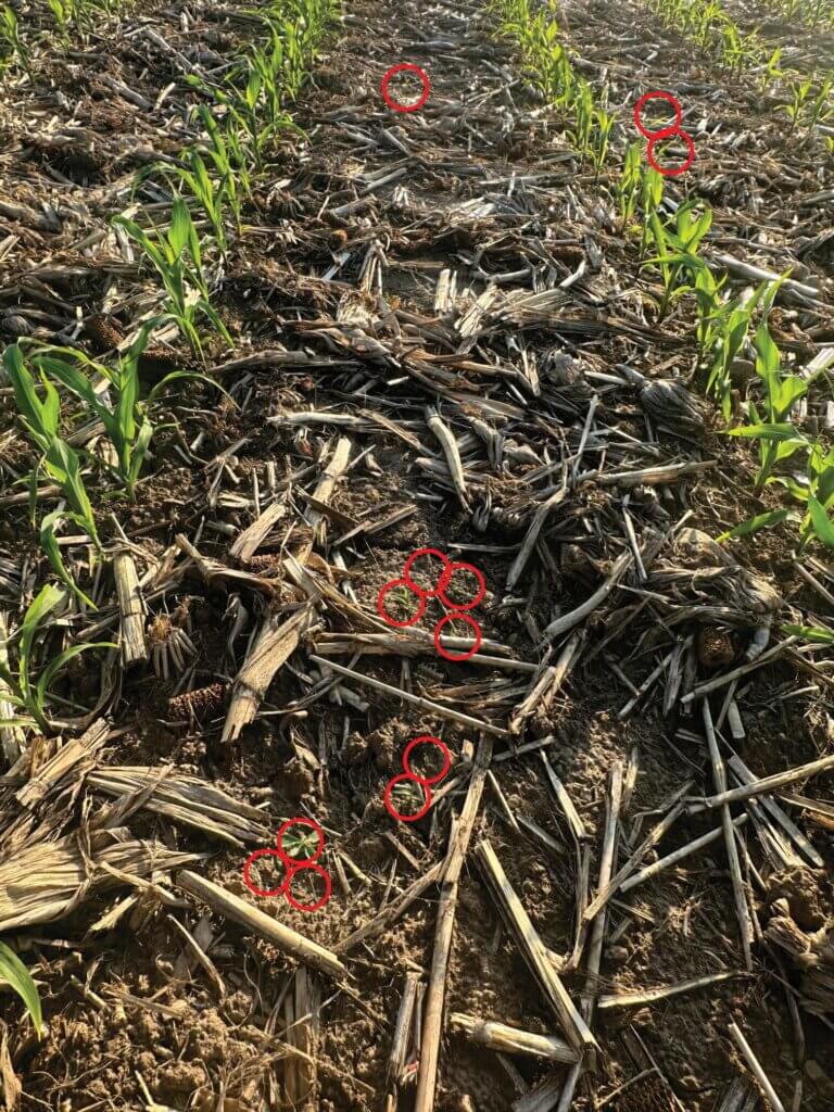
    As expected, visual scouting underestimated real weed density. Figure 4 might seem clean at first blush, but the cameras see a different story hidden in the stover (Figure 5). This is why predictive tank‑mix planning is unreliable.

    Figure 5 – Weeds may hide from a scout, but not from clever optics.

    Optimizing Tendering Through Job Planning

    Todd found that the best approach to minimizing leftovers was to group farms with similar pre‑emerge programs and weed spectra. He would then book them from the smallest to the largest fields, allowing leftover spray mix from smaller jobs to feed into larger ones. His goal was to finish with <5 acres worth and broadcast it at the end of the last job.

    This kind of planning starts with the fall burndown and should be firmly in place by March. It’s already challenging to accommodate last-minute requests during spring spraying, but this approach makes it particularly difficult.

    Customer Scheduling Challenges

    There was some frustration along the learning curve. A few customers experienced delays waiting on sprayer availability and then paid the premium on a field that ended up requiring a broadcast application. Experience will help refine expectations and scheduling.

    Looking Ahead: 2026 and Beyond

    In 2025, the See & Spray machines in Ontario sprayed mostly soybean, but in Todd’s region it was predominantly corn. One reason was that most of his soybean customers weren’t quite sold on the fall application. Todd has plans to get into soybeans in 2026, but his strategy involves IP beans.

    Traditionally, IP beans get a spring application timed to catch as many weeds as possible, perhaps too late for some and too early for others. Then Todd takes his phone off the hook as customers fret over burned beans while they inevitably grow out of the visual injury. But this time, Todd will make two targeted passes with a more expensive tank mix to do a better job of controlling weeds at the right stage, while avoiding burning the IP beans. If his projections are correct, he believes he can accomplish this more economically than a single broadcast pass.

    We’ll update this article with the outcome. Be sure to check back and see if he succeeds 🙂

    Conclusion

    Ontario’s early experience with green‑on‑green optical spraying suggests that while the technology is promising, it requires substantial logistical planning, label awareness, and nozzle optimization. Under the right conditions—particularly where weed pressure is irregular but significant—operators can achieve both economic savings and precise weed control.

    As adoption increases and equipment evolves, we’ll learn more about where spot and patch spraying technology fits in changing weed management programs.

    Thanks to Todd for sharing his experience and insights.

  • Recirculating Boom Options

    Recirculating Boom Options

    If you read this site, you know we’re fans of recirculating booms. We love them for three reasons:

    1. They save money and waste by recovering spray back to the tank during priming and rinsing
    2. They make boom cleaning easier by eliminating boom-ends
    3. Most require individual nozzle shutoff, which makes for better sectional control

    If you’re new to the concept of recirculating booms, read more here.

    Until recently, these booms were only available on sprayers imported from outside North America (Horsch, Amazone, Agrifac to mention three), or via France’s Pommier booms that have been available as retrofits for many years. In 2018, Agco introduced their Liquid Logic system on the Rogator line, becoming the first North American manufacturer to offer a recirculating boom at the factory. Pattison Liquid also offers Recirculating booms as standard equipment on their Connect Sniper pull-type sprayer.

    In the meantime, three boom retrofit kits and one sectional conversion kit have become available.

    Arag Australia‘s BRS (Boom Recirculation System)

    The first was developed by Arag Australia, and is available there via Nozzles Online, and in Canada through Nozzle Ninja. Designed for John Deere R-Series and Case Patriot sprayers, the kit uses the existing line that feeds liquid to the outermost section and simply extend that line to the end where it enters the boom via two installed elbows. The liquid returns to the centre via the installed boom sections which are connected together by removing the boom end cap (or “aspirator” for John Deere) and replacing the gap with a section of hose. Back at the centre rack, the liquid from both booms meet in the middle. At this point, a three-way valve gives the choice to return the spray to the tank, or to receive pressure from the pump. There is also a manual valve that allows the return to be dumped for safe disposal.

    Arag Boom Recirculation System (Spray Mode)
    Arag Boom Recirculation System (Recirculation Mode)

    The system does not tie into the sprayer’s electronics. instead, it adds a switch in the cab that the operator uses to switch from spray mode to recirculation mode. The switch is not activated at the end of each swath, but instead to prime or flush the boom.

    A switch is added so the user chooses recirculation or spray mode. The boom would recirculate to prime or flush, and remain in spray mode during the spray operation.

    Raven

    Raven offers a recirculation kit for 3000, 4000, and 5000 series Case Patriot sprayers with Aim Command HD and an ISOBUS terminal. The approach is slightly different, as they retain the pressure feed through individual sections but also tie the sections together so the spray is returned to the tank. By including a shutoff valve between each section, the system retains the option to use conventional sectional control for high flow situations, or to isolate a section should a leak occur. The system can be configured and controlled from the sprayer monitor, either a Viper 4+, CR7, or CR12.

    Raven Boom Recircualtion System schematic (from Raven manual). Note the retention of section valves and the addition of manual valves between sections.

    John Deere

    On March 2, 2021, John Deere announced a 2022 factory option called Pressure Recirculation and Product Reclaim. The system keeps several existing sections and adds two steel lines the flull length of each boom wing. One is for supply, the other return. As these lines approach a section, the supply is fed to one end of the section and the return is connected to the other end. On a 120′ boom, there are five recirculating sections, two on each wing and the centre.

    This approach adds one more line than the other designs, and this line will hold materials that ultimately need to be cleaned, flushed, and possibly dumped or sprayed out for cleanout. A possible reason for the extra line is the ability to deliver 220 gpm to the boom, an advertised feature of John Deere high flow booms that may come in handy for topdressing liquid fertilizer. These levels of volume are not needed for pesticides.

    John Deere Boom Recirculation and Reclaim. Top two lines are supply and return and extend the length of each boom wing. These connect to the existing sections on each wing, creating several smaller recirculating sections.

    Latitude Ag

    This Wisconsin company has developed an innovative product that converts any existing plumbed section that contains boom ends into a recirculating section. It does this by incorporating a boom recirculation valve” (the “Merlin IC System“) into the original section feed line. Boom end caps are removed and replaced with sweeps and hoses that return flow to these boom valves. The flow from the boom ends is incorporated back into the sectional feed thanks to a venturi design in the recirculation valve.

    A prototype of the Merlin IC System valve made by Latitude Ag

    Advantages of this design include simplicity. No moving parts are required, the valve simply recirculates the flow from the boom ends automatically whenever that section operates. Existing sectional control, whether it’s by plumbed section or individual nozzle bodies, is unaffected. Flushing the boom with water is done with normal spraying. It takes some extra time to incorporate and dilute the contents of the boom end return lines but results in a clean boom and no section end residue. We’ve seen the results of testing and agree that it works.

    This product does not allow boom priming without spraying. However, a key advantage is that it can be used with direct injection since no product is returned to the tank. Latitude Ag says it will provide the necessary flow sensor and software to make this possible. As of 2025, this system may no longer be commercially available.

    Precision Planting ReClaim

    ReClaim is capable of operating on a sprayer with or without individual nozzle shutoff. For conventional nozzle bodies containing the original spring-loaded diaphragm check valves, the concept is to drop the liquid pressure below the cracking point of the check valves so flow continues through the sections and back to the tank without engaging the nozzles.

    Recirculation fittings are added to the end of each boom section. These feed into 3/4″ lines are installed on section ends, which in turn feed increasing diameter collector lines that eventually return all flow to the tank. Flow reaches the sections as before. When recirculation is turned on, flow exits the boom section through the new fittings and returns through 3/4″ lines to the centre of each section, where it enters 1” lines that take the flow to the center of each boom wing. There the flow in the 1” lines is combined moves to the center of the sprayer on 1.5” lines where it meets the flow from the other wing.  From there, the flow returns to the tank through an electronic ball valve and 2” line. This system ensures no back-pressure and balanced flow from each section.

    For some sprayer rate control systems such as John Deere, the pump won’t operate below about 20 psi despite operator settings. This means the priming or flushing procedure would trigger nozzles to spray if the bodies were fitted with spring-loaded diaphragm check valves. A pressure reduction kit (a second restrictor valve) is required to reduce the pressure sufficiently for ReClaim to work in these instances. More here.

    ReClaim operates independently of any electronic control systems, relying on a toggle switch to initiate recirculation. When flow back to the tank is detected, a light indicates that recirculation is working, and the operator waits approximately 60 sections for a 120’ boom to circulate all volume back to the tank. Download the operator’s guide, here.

    This system requires a lot of additional lines. A 120’ boom would require 120’ of additional 1” line and 60’ of 1.5” line. The manufacturer states that ReClaim adds about 14 gallons of volume that would need to be displaced back to the tank, adding to the standing volume. This volume can be circulated using solution from the main solution tank, or displaced back to the tank using flow from an existing clean water tank, or displaced using compressed air via an optional pneumatic port. It is not clear how spray mix in the ReClaim system can be removed from lines without returning it to the tank and draining it from there. Users should consider the additional surface area and volume that will have to be addressed during cleanout.

    Do It Yourself

    If none of the available options work for your sprayer, consider building your own system. Sprayer plumbing parts are available from the major manufacturers Banjo, Hypro, TeeJet, and Wilger. Wilger, in particular, has developed a nice suite of parts well suited to recirculating booms, including flanged sweeps and thin gauge steel booms, punched for nozzle bodies or unpunched to move product. See their support for DIY projects on this dedicated page: Wilger Retrofit.

    Take Home

    All these recirculation options improve the status quo of plumbed boom sections with boom ends. They should be considered essential equipment on sprayers.

  • Broadcast Boom Nozzle Spacing

    Broadcast Boom Nozzle Spacing

    North American built boom sprayers have nozzle spacings of 20” (50 cm in the rest of the world), but other spacings such as 15” (37 cm) and 10” (25 cm) also exist. What are the reasons for these alternative spacings and do they offer any inherent advantages?

    Why spacing matters

    Nozzles are spaced along a boom to allow their fans (patterns) to overlap sufficiently at the target. In broadcast spraying, a uniform distribution of spray volume gives us the best chance for consistent coverage along the boom. Since flat fan nozzles produce a tapered pattern (i.e. the volume is highest in the centre and diminishes towards the edges), approximately 100% overlap (i.e. 50% from each neighbour) will produce a uniform swath.

    Figure 1: Tapered flat fans that require some overlap are the default pattern type for agricultural boom nozzles. This is true of conventional and low-drift styles. Note that the flat fans are turned 15° to prevent the spray patterns from interfering with one another.

    The 100% overlap isn’t just for volumetric distribution. Flat fan spray patterns tend to have more and finer droplets in the centre and fewer and coarser droplets at the edges. All droplet sizes contribute to coverage in different ways, so the overlap ensures both number and sizes are evenly distributed along the entire boom.

    Figure 2: 30% overlap may achieve volumetric uniformity. But because the centre of the pattern contains the majority of the smaller droplets, low overlap may result in low coverage in the overlap regions, resulting in striping.
    Figure 3: Consistent droplet number distribution along the boom requires at minimum 100% overlap (50% from each neighbouring nozzle). This blends those regions of the patterns with high and low droplet densities.

    The generic 20” spacing arose from long-held conventions about boom height, fan angle, and travel speed. Specifically, this spacing required a boom height of 20” to obtain good overlap of the once-dominant 80° fan angle. Combined with 0.15 to 0.3 US gallon per minute (gpm) nozzles and travel speeds of 6 to 8 mph, operators were able to apply 5 to 15 US gallons per acre (gpa) volumes. Using nozzles with smaller flow rates would generally result in nozzle blockages.

    But what if we want to change any of those variables? How does this affect nozzle spacing? Figuring out the pros and cons of an alternate spacing requires a little math and some contingency management.

    Boom Height Math

    First the math. If the boom has 20” nozzle spacing and we need 100% overlap, the width of the spray pattern at target height must be two times the nozzle spacing, which is 40″. You must calculate the required fan angle and boom height to achieve this. Most nozzle catalogues have tables to help with this, or you can download a handy spreadsheet to calculate your own scenarios here.

    For today’s standard 110° fans, a minimum boom height of 14” is needed to achieve 100% overlap. For 15” spacing, the height is reduced to 11”. For 10” spacing, we drop to a mere 7”. However, consider that most modern suspended booms are not operated at heights less than 24” to allow for sway. At that height, there’s plenty of overlap to go around for 20″ nozzle spacing. For those booms that are able to operate at a consistent height, narrower spacings permit lower heights that will reduce drift potential significantly. Every time we halve boom height, we also halve drift potential.

    Figure 4: Using 110° tips with 20″ spacing, the theoretical height at which we achieve 50% overlap is 11″ above target.

    By tilting the nozzles forward or backward from the vertical, we can reduce the boom height somewhat further and still get the same overlap. For example, for 20 and 15” spacings, angling nozzles forward or backwards by 30° allows us to drop the boom another 2” closer to the target.

    Contingencies

    A suspended boom hardly ever stays at a uniform height; It sways up and down with field conditions, topography, etc. This is why many operators set their booms above the minimum height – to prevent striping when the boom sways low. The penalty is that this increases the distance droplets need to travel, increasing drift potential and any turbulent displacement problems arising from the moving boom.

    Assuming a 110° flat fan at 24” boom height, each nozzle achieves a theoretical pattern width of about 70”, which is an overlap of 70÷20=3.4-fold or 240% on 20” nozzle spacing. Given a minimally-acceptable overlap of 50% (25% from each neighbouring nozzle), the boom could be as low as 11”. For 15” spacing, the minimum height for 50% overlap is 8”, and for 10” spacing it’s 5”. This means the narrower spray patterns gain 3” to 6” in allowed downward boom movement.

    Figure 5: Using 110° tips on 15″ spacing, the height for 50% overlap is 8″ above target.

    A second contingency is that spray patterns are rarely the exact value that the nozzle catalogues specify. A so-called 110° nozzle may operate at only 90°, or up to 150°, depending on the nozzle model, the spray pressure, and the tank mix. Learn more here and here. Patterns also don’t continue to grow at their rated fan angle, as droplets slow due to air-resistance and fall more vertically due to gravity. For that reason, a visual check is recommended to ensure the expected overlap is achieved.

    Figure 6: Fan angles indicate initial trajectories of droplets at the edge. With distance, gravity pulls these droplets downward, narrowing the pattern width from that achieved theoretically (figure adapted from image in TeeJet catalogue).

    A third issue to consider is less related to boom height but nonetheless affects spray distribution. Small droplets move with air currents, and the turbulence created by large, fast sprayers creates enough turbulence to move these droplets significantly. A perfect pattern under static conditions can look quite different at a fast travel speed with a modest side wind. Low booms may help prevent some of this displacement because droplets spend less time in flight, and their average velocity is faster.

    Figure 7: Spray deposition onto a 2 mm string to measure deposit uniformity for a fast travel speed and high boom and a slow speed, low boom configuration.

    Flow Rate Math

    Flow rate requirements per nozzle change whenever we equip a boom at an alternate spacing. The basic formulae are shown below.

    Moving from a 20″ to a 15″ spacing would require a nozzle with 0.75 of the flow rate, approximately from a 02 to 015 size, or 03 to a 025 size, or 04 to 03 size, etc.

    Pulse Width Modulation

    The use of Pulse Width Modulation (PWM) has increased the overlap requirement. With PWM, alternate nozzles are on a 180° timing offset from their neighbours. This means that when running >50% duty cycle, when one nozzle is temporarily off, its neighbours are on. These neighbours’ patterns must now span the gap, and 100% overlap is the absolute minimum to achieve this. PWM users therefore select the wider pattern angles and some opt for >100% overlap.

    Figure 8: Pulse Width Modulated booms require 200% overlap so that the entire boom receives proper coverage when the alternate set of nozzles is off. For 110° fans at 20″ spacing, the minimum boom height would be 21″

    PWM Considerations

    • High flows (greater than 1 US gpm at the nozzle) that are common for fertilizer top-dressing may require higher-flow PWM valves.
    • Narrow spacings reduce the individual nozzle flow rates and can therefore support higher application rates before triggering a larger valve requirement.
    • PWM valves aren’t cheap and for example 15″ spacing compared to 20″ spacing adds 24 valves on a 120′ boom.

    Banding

    We noted that 20” nozzle spacing is a standard because it corresponds to what has traditionally been achievable with available boom heights and spray pattern angles. But things can change.

    Narrower spacings such as 15” originate with row crops and planter row spacings of 15” or 30”. These spacings exist so the spray pattern can be placed either over the top of a crop row, or in between the rows for banding. Using narrower fan angles and/or lower boom heights, together with “even” (as opposed to “tapered”) fans, banding sprays can be applied over the top of, or between crop rows. Or drop hoses can reach between the rows for top-dressing or directed sprays into the canopy.

    Canopy Penetration

    With narrower spacing, it can be argued that a greater proportion of the boom length has spray directed directly downward (corresponding to the centre of the pattern). Whether or not this translates into better penetration of a canopy is a fair question. In laboratory trials, use of 10” or 20” spacing did not improve penetration into a broadleaf canopy. But if the lower boom height afforded by the narrower spacing was utilized, some improvements in the deposit of angled sprays onto vertical targets was observed.

    Adjusting to Narrower Spacings

    As we showed earlier, use of 15” or 10” spacing booms for broadcast sprays requires a smaller nozzle size to achieve the same spray volumes as the 20” spacing. If boom height remains constant, narrower spacings result in greater pattern overlap which provides more latitude for sway. Alternately, lower boom heights can be used.

    Using smaller nozzles on narrower spacing presents some challenges. Generally, smaller nozzle size means finer spray quality. If an operator wants to retain the spray quality they had on a 20″ spacing, they may opt to use lower pressure (not advisable for non-PWM systems) or swap to different nozzle design that can produce the desired spray quality at the lower flow rate.

    Smaller nozzles are more prone to plugging, so that needs to be managed with filtration, filling practices and water sourcing. Be aware of the the product formulations and their requirements for filter mesh size. Most dry products specify a 50 mesh filter (or coarser). Also, check size options for nozzles. The smallest size for most nozzle models is 015, but certain PWM-specific nozzles are only available in 03 or larger.

    The marriage of narrow spacings with individual nozzle shutoff can result in a versatile system capable of producing high resolution banded sprays in narrow seeded crops. For example, consider a boom with a 10” nozzle spacing spacing that matches the seeder row spacing. The operator can shift from 10” to 20” or 30” from the cab if the valve control software allows it. With accurate guidance and good boom levelling, topdressing foliar products (e.g. nutrients, fungicides) can follow the crop row precisely.

    Spot Sprays

    Spot sprays present a situation where compromises are needed. Some, such as WEEDit, utilize narrower nozzle spacings to allow better treatment resolution and increase product savings. Any one nozzle or sets of adjacent nozzles may be triggered by the sensor. For single nozzle activation, to preserve the value of the better resolution a uniform, narrow band of spray needs to be created. This means a 30° or 40° fan angle from a banding nozzle will be necessary. For example, a 24” boom height will result in a 13” band with a 30° fan, and an 18” band with a 40° fan. In the latter case, the dose would be diluted by 80%, wasting much of the potential savings.

    Figure 10: Boom height is critical for banded sprays and for spot sprays. Too wide a pattern on a single nozzle reduces dose, too narrow creates misses.

    Frequently, a patch of weeds will trigger several adjacent nozzles. Now these individual bands need to work together to create a uniform swath. This will inevitably require some overlap to avoid gaps, but too much overlap will result in bands where twice the dose will be applied. A tapered fan may suit this situation better. As a result of these varying needs, tolerances for spot spray boom height are even more strict than for broadcast spraying. More thoughts on spot spray nozzle selection are here.

    Conclusions

    Narrower nozzle spacings on a broadcast boom allow somewhat lower boom heights and these can in turn reduce drift and improve deposition of sprays. Lower flow nozzles will be needed with narrower spacings, requiring management of plugging and potentially a more drift-prone spray quality. The value of narrower spacings depends on the availability of booms that control sway, allowing them to operate at uniform, low heights.