Tag: PWM

  • What do European Sprayers Bring to the North American Market?

    What do European Sprayers Bring to the North American Market?

    For many years, European agricultural machinery was considered too small to be relevant for North American conditions. That started to change when Claas and New Holland began introducing large harvesting equipment 20 yrs ago. Larger tractors from the likes of Fendt, and seeding and tillage equipment (e.g. Horsch) followed soon after. Now, European sprayers are knocking on our doors. What do they bring to the party?

    Overall capacity

    The typical large self-propelled European sprayer of 2020 has all the capacity of the largest North American models, and sometimes more. Boom widths of 36 m (120 ft) are common, and wider booms extending to 40 and even 50 m (~131 and 164 ft) are available. Tank sizes of 5,000 and 6,000 L (~1,300 and 1,600 US gal) are not uncommon, and 8,000 to 12,000 L (~2,000 to 3,000 US gallons) are featured on some. On those specs alone, they qualify.

    European sprayers can be significantly larger than their North American counterparts (Dammann DT 3500 H S4).

    Dimensions

    The first thing people notice about European sprayers is their more compact design. In order to comply with the 3 m maximum transport width allowed by law, everything is narrower. That doesn’t prevent the wheel track from widening in the field, of course, where stability is needed or where tramlines need to be matched.

    More efficient use of space in a European sprayer allows a smaller sprayer footprint with equal capacity (Amazone Pantera).

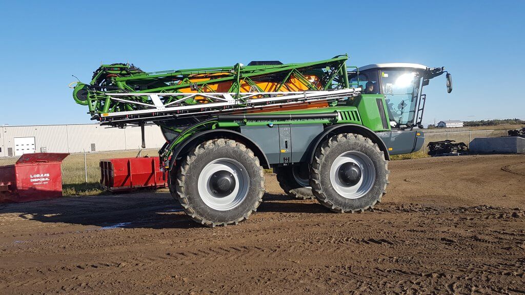
    The more compact design does come at a cost. There’s no room for large ladders with handrails to enter the cab, and catwalks are usually gone, too. Access to service points can be more cramped. But the upside is that most of these sprayers are lighter than their North American siblings, with dry weights between 9,000 to 12,000 kg (20 – 25,000 lbs) not uncommon even for the larger capacities.

    Compact, efficient designs featured in Bateman sprayer, one of UK’s top makes.

    Frame and Cab

    Less space has provided some frame innovations. A central channel frame is sometimes featured, creating room for a sophisticated swingarm suspension, or a walking beam. The cabs typically sit in front of the chassis, with a centrally mounted engine. This offers superior visibility, although it does take some getting used to. Overall, the cabs on these more compact sprayers are every bit as spacious and comfortable as North American types, with better rearward views possible due to the narrow chassis.

    Wishbone swingarm from central tube frame in Fendt Rogator.

    Monitor systems vary, but due to the majority of sprayers being made by smaller firms, third-party controllers will be more likely. Ag Leader, Topcon, and others can be seen in place of the proprietary systems of the larger manufacturers.

    There are no shortcuts with European cabs.

    Tank design

    Again, the compact real-estate requires some unique solutions. The barrel-shaped tank resting on a cradle that we’re used to in North America is replaced by a more complex-shaped tank that needs to utilize every possible available space. Although this is done with steel on many units, molded plastic is once again more common. Access to the tank lid is also more difficult due to the general absence of walking platforms. However, attention is paid to sump design and minimizing the remaining volume, making cleaning easier.

    Less room on narrow frames requires more complex tank shapes. Will cleanout be as effective?

    Booms

    European sprayers have well-engineered booms with better height control and contour-following capabilities than North American units. Usually triple-fold, they are compact and many offer Norac (Topcon) height sensors. Steel remains the most common material, with aluminum deployed as necessary on outer sections. Wet booms have 25 mm outside diameters and as such are slightly smaller than North American types. However, flow and pressure drop are measured to ensure a quality distribution. If these systems are used at faster travel speeds, flow limitations may become an issue and that will require closer evaluation.

    Large tanks and wide booms are commonplace in Europe (Sands sprayer)

    Plumbing

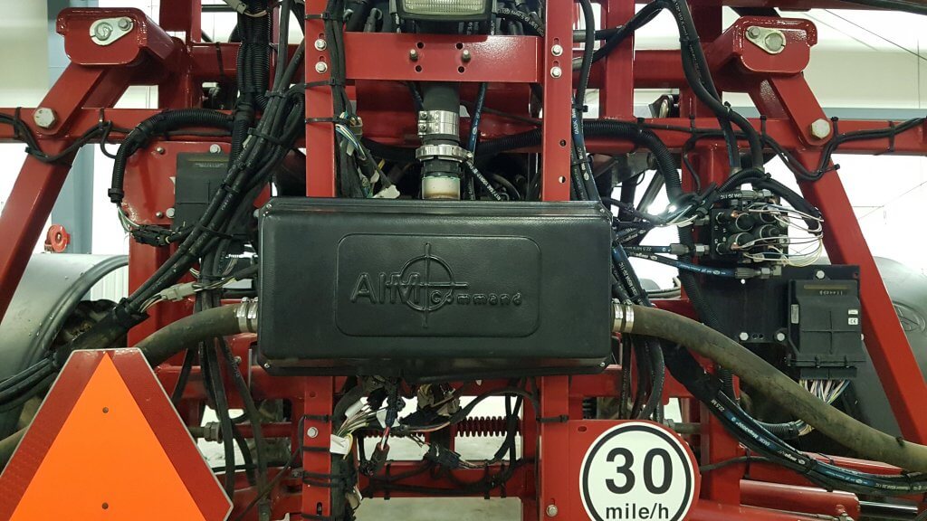
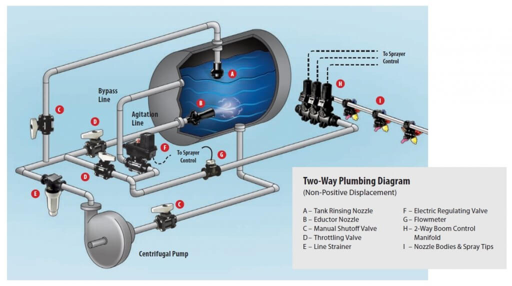
    An aspect where the European sprayers excel is plumbing design. Most have recirculating booms; some offer continuous rinsing. Both designs minimize waste generation and simplify rinsing and cleaning, saving time. More sophisticated tank level gauge systems that offer cab readouts, better resolution at low volumes and less dependence on having the sprayer resting on a level surface, can also be seen.

    Recirculating booms are common on European sprayers (Bateman sprayers).

    Pumps tend to be diaphragm, with only a few brands offering centrifugal types. The reasons are both technical and traditional. On the one hand, diaphragm pumps can run dry, don’t need to be primed and can be located beside the tank, for example, and can push air into a boom. On the other, they are bulkier and more expensive, noisier, need a pulsation damper and require maintenance. Some manufacturers, notably the Fendt Challenger and the Chafer, ship with centrifugal pumps. These are now equipped with wet seals, and the Challenger has employed an auto-prime system that prevents air-locks.
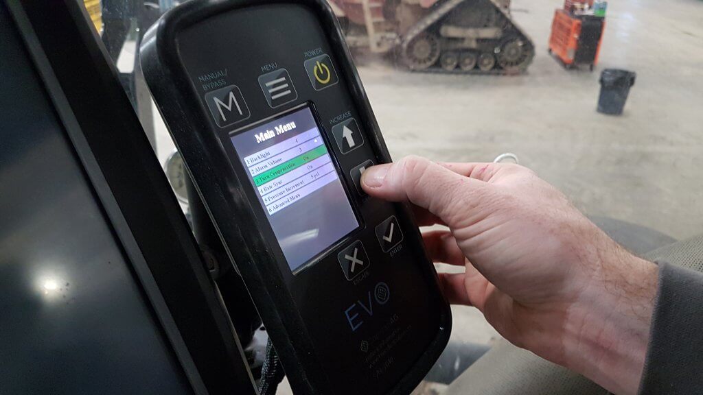
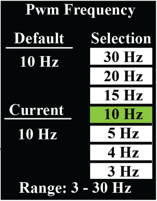
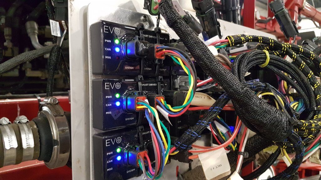
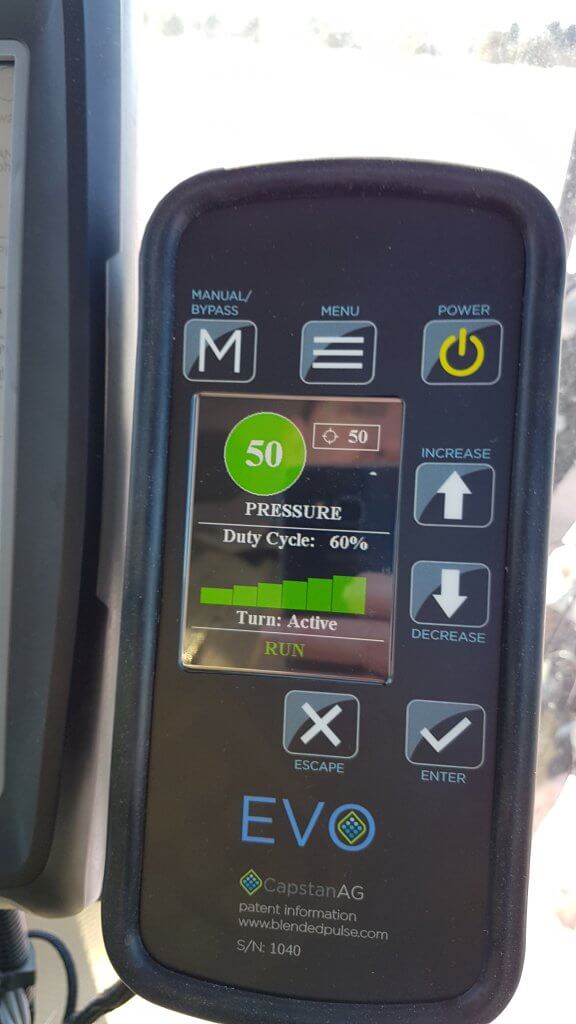
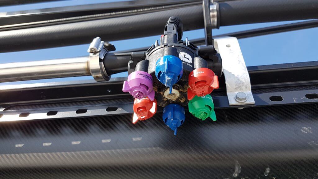
    Diaphragm pump on Amazone Pantera (top of picture)

    Flow Control

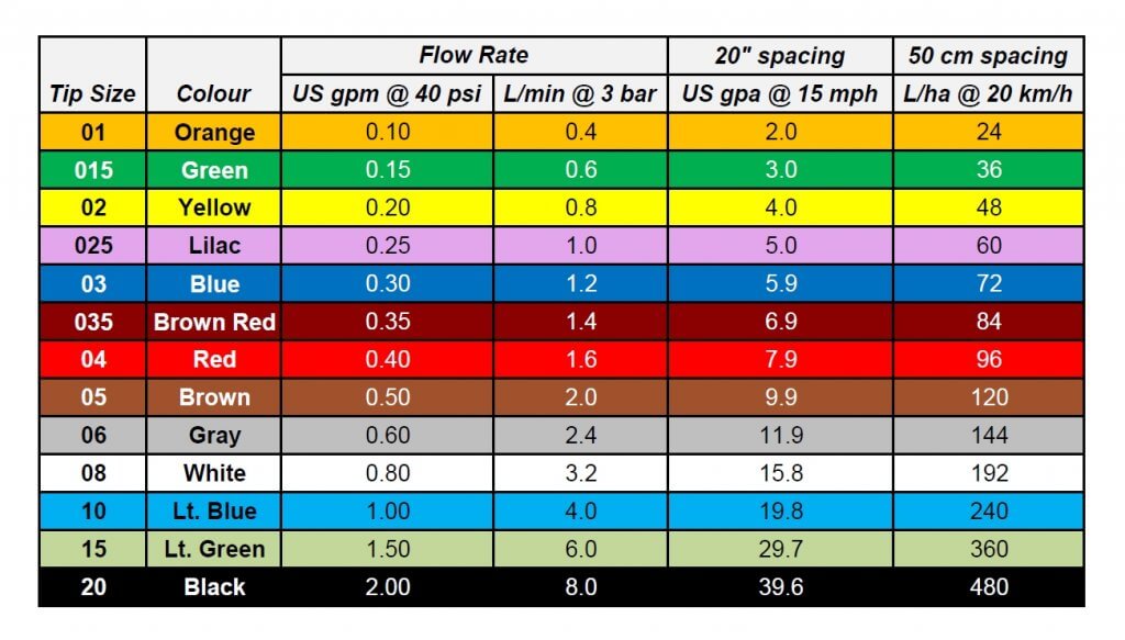
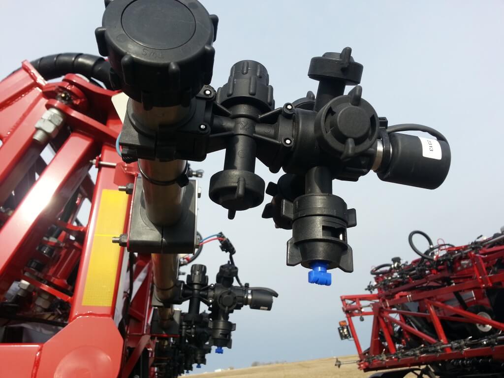
    Whereas all North American manufacturers offer a pulse-width-modulation (PWM) option which now comprises an estimated 30% of new sales, the European sprayers are only beginning to consider this flow management approach. The majority still offer multiple nozzle bodies that permit automatic switching between various sized nozzles to achieve extended travel speed ranges or changes in spray quality. One of the reasons for the delayed adoption of PWM is the European regulatory system, which have yet to approve some aspects of the PWM system.  Low-drift performance, for which most air-induction nozzles have been approved, must still be validated for nozzles that must be used with PWM (recall that air-induced nozzles are not generally recommended for PWM).

    Multiple nozzle bodies are favoured over PWM in Europe, but PWM is gaining acceptance.

    Many UK sprayers also use an interesting means of managing bypass, via a so-called Ramsay Valve. This type of valve uses an air-filled diaphragm to divert flow, and air-pressure change is used to alter the bypass. Such a system was an answer to early butterfly valves which had slow, uneven response, but is bulkier than the modern mechanical bypass valves now available, and may require maintenance.

    Drivetrain

    Like North American sprayers, wheels are driven by hydraulic motors. Hybrid Continuously Variable Transmission (CVT) systems are also available, and these offer superior torque characteristics at slower speeds. Engines are like those offered in North America, supplied by major manufacturers such as John Deere, Deutz, Fiat, etc. We are seeing smaller engines on European sprayers owing to the slower travel speeds. Slower speeds don’t just save cost, weight, and fuel consumption, they also provide the advantage of better boom height control and lower spray drift, as long as productivity can be maintained.

    Wheels

    European sprayers generally use the same wheel sizes as North America, with 46” wheels being common. A unique feature of UK sprayers is their use of 28 to 38” wheels. Although native ground clearance is sacrificed, it is enough for most crops except for corn, for which many sprayers require a lift kit anyway. These smaller wheels allow booms and other components to be cradled lower, improving the centre of gravity and safety.

    Wheel sizes vary, but are sometimes significantly smaller, particularly in the UK.

    Summary

    There is very active competition between European sprayer brands. Many dozens of manufacturers are in the market, and customers have high expectations. Although some of the features on European sprayers will appear strange at first sight, they should be evaluated purely on performance criteria, not aesthetics.  Does the sprayer improve efficiency by reducing downtime?  Does it make drift control easier? Does it waste less product that one would otherwise dump on the ground? Is it more fuel efficient? In this regard, customers will benefit from the competition introduced by other sprayer brands. A rising tide lifts all boats.

  • The Capstan EVO: PWM for the masses

    The Capstan EVO: PWM for the masses

    Capstan Ag brought Pulse Width Modulation (PWM) to spraying in the mid 1990s. Over the past 20 years, it has become commonplace on Case sprayers as AIM Command and AIM Command Pro, and as an aftermarket product, called Sharpshooter or PinPoint, on any brand sprayer. If you’re new to the concept, read about it here and here.

    A sprayer turn, without turn compensation. Note the darker dye on the innermost nozzles and lighter deposits on the outer wing.

    The latest versions (AIM Command Pro and PinPoint) offer turn compensation and individual nozzle sectional control. But there remains a large base of older AIM Command units that lack turn compensation. And of course, sprayers that lack PWM alltogether, possibly because of cost.

    The Capstan EVO addresses both issues. Introduced in January of 2019, it gives older AIM Command units affordable turn compensation. As a bonus, a complete new EVO install on non-PWM sprayers is available at a significant discount compared to most other PWM products.

    EVO features many of the same basic PWM capabilities as its bigger cousins, but with a shortcut, explain Capstan representatives.

    As always, a change in travel speed changes the duty cycle of the pulsing solenoid, adjusting flow rate of the nozzle without a change in pressure. This provides the consistency in performance that we love about PWM. Drift or coverage are controlled by the operator who makes changes to spray pressure from the cab, with a commensurate background adjustment in duty cycle so that travel speed is unaffected.

    With the EVO, the shortcut is that sectional control is by plumbed section. Technically it’s possible to add sections, but the rate controller and the sprayer wiring would have to allow it.

    Spray dosage for sectional turn compensation for six sections of equal size, with the centre of each section applying the target dose. As always, some lateral movement of spray from adjacent nozzles will occur.

    Turn compensation is part of EVO, and this is an important benefit that was previously only available in more expensive versions of a PWM product. Each section will have a fixed turn compensation based on the speed of the centre of the section. Its performance will depend on the size of the sections.

    For a 100′ boom with six 10-nozzle sections turning around an object with a 60′ diameter, our modelling shows that the deviation from perfect turn compensation is least on the outer wings (where it’s most important) and grows towards the inside of the turn. In this example, the outer section’s end nozzle under-applies by 6% relative to the ideal, and the innermost nozzle on this section over-applies by 7%.

    On the next section, these deviations are 7% under and 8% over, then 8% under and 9% over.

    Moving from the centre of the sprayer to the inner wing, deviations are 9% under and 12% over, then 12% under and 16% over, and finally 16% under and 24% over.

    Spray deposition on an un-compensated turn.

    On an uncompensated boom with the same dimensions, the outermost nozzle would be under-dosing 38% and the innermost nozzle would be over-dosing by 267%.

    Recall that it’s more important to be accurate on the outer wing than on the inner, for the purpose of delivering the full spray dose in a turn.

    Repeated year-after-year under-dosing at the periphery of a turn such as field corners, or around permanent features such as sloughs, trees, or stone piles results in weed problems.

    EVO is intended for users with an original SharpShooter or AIM Command who would like turn compensation but don’t want to a whole new PWM system. EVO provides new modules and a new screen, but users save money because they can keep their existing solenoids, says Capstan.

    Capstan says that EVO is for every brand of sprayer ordered without pwm control from new to 15 years old. It’s an easy upgrade for owners of AIM Command & SharpShooter systems because these already have most of the components, and install times are therefore lower for these machines. Existing solenoids and wiring harnesses can be retained.

    Owners of high clearance pull type sprayers will also see the advantage of turn compensation and pressure control at an attractive price point.

    EVO modules and tools needed for installation

    I was present during an installation of these new modules on an existing Case 3330 sprayer with AIM Command. It took one person, with occasional assistance from a second, less than 1 h to do the conversion.

    Removal of AIM Command modules
    Installation of EVO board containing all modules and replacement plugins

    A new installation would require an additional several hours to install wiring harnesses and solenoids. Times will vary with sprayer model and technical experience of the installers.

    The EVO electronics run in parallel to the existing sprayer monitor. It allows the existing monitor to control sections and determine the flow requirements. It does not control pump speed, it simply reads the flow, pressure, and gps signal from the sprayer’s systems and uses them to determine the duty cycle (DC) that ensures the spray pressure remains constant. On AIM Command units, the pressure control module remains installed and pressure adjustment remains possible through AIM Command in cab controls.

    Entering system settings into new EVO monitor

    It’s possible to set the pulsing frequency between 3 and 30 Hz in EVO, an industry first. The lower the frequency, the wider the dynamic flow rate. Capstan advises to maintain a frequency above 10 Hz for spray operations. Lower frequencies may be used for fertilizer applications, where prescription maps require a higher rate range and where uniformity requirements are more relaxed.

    EVO Monitor contains an option in which to select pulsing frequency
    Testing of completed EVO Installation

    The monitor has an intuitive readout of average DC and a bar graph showing the DC across sections in a turn. If this bar maxes out on the outer sections during a turn, simply slow down to lower average DC and provide extra capacity to those sections.

    EVO monitor during operation. Readout includes current spray pressure, duty cycle, and turn compensation status.

    Lowering the cost of PWM makes it attractive to a new group of users. It also offers a more affordable upgrade path for owners of AIM Command or SharpShooter systems that currently do not have turn compensation.

    The cover says AIM Command, but the guts are EVO
  • Six Spray Technology Skills for Agronomists

    Six Spray Technology Skills for Agronomists

    Press play to listen to an audio version of this article

    Agronomists help farmers manage their crop with advice on everything from crop cultivars to fertilizer rates to marketing. It’s challenging to be an expert on everything, but a few core competencies can go a long way to improving the level of service.

    Agronomists are also responsible for communicating environmental best practices. Along with fertilizer rates come messages of source, time, and place, the 4R principles. The same is true for spraying, with messages of spray drift, resistance management, and economic thresholds part of the consultation. Let’s remember that we should not be indifferent to the potential consequences of our recommendations.

    Here are six skills that an agronomist should know about spray technology.

    1. Recognizing major nozzle models and their spray quality and pressure requirements.

    Application technologists are often asked to identify nozzles and recommend spray pressures for clients. It’s a skill that anyone can develop with just a bit of homework.

    First, learn the colour-coding of nozzles – colours identify flow rates and follow an international standard that all manufacturers have adopted.

    ISO Colour coding of major nozzle sizes, as well as application volumes at benchmark speeds.

    Next, focus on the common nozzles on the major sprayers. John Deere sprayers will typically have three main air-induced nozzles, made for John Deere by Hypro, the Low-Drift Air (LDA), the Ultra Low-Drift (ULD), and the GuardianAIR Twin (GAT). Those with ExactApply, John Deere’s PWM system, will see the non air-induced 3D, the Guardian (LDX), and the Low-Drift Max (LDM). Recall that PWM flow control should not be used with air-induction tips.

    Almost all Case sprayers have PWM, called AIM Command. Case uses Wilger ComboJet bodies and nozzles, with the ComboJet ER, SR, and MR most common, sometimes the DR or UR for dicamba.

    New Holland/Miller with PWM (called IntelliSpray) are also likely to have these tips, but because these brands have TeeJet bodies on their booms, they require an adaptor for the proprietary ComboJet caps.

    Otherwise, PWM units often use TeeJet’s TurboTeeJet (TT), Turbo TwinJet (TTJ60), and Air-Induced TurboTwinJet (AITTJ60), the only air-induced tip approved for PWM use by TeeJet.

    Conventional spray systems (i.e., no PWM), will commonly have (in alphabetical order) the Air Bubble Jet (ABJ, actually labelled BFS for their manufacturer, Billericay Farm Systems), the Greenleaf AirMix (AM), the Hypro GuardianAIR (GA), and the TeeJet AIXR.

    Many sprayers will have a twin fan for fungicides, primarily for fusarium headblight (FHB) management. The Greenleaf Turbo Asymmetric Dual Fan (TADF), the Hypro GuardianAIR Twin (GAT), and the TeeJet AI3070 dominate, as well as a number of custom configurations using splitters and twincaps.

    Where dicamba is applied on Xtend trait soybeans, some special nozzles may be used to meet label requirements for coarseness. The TeeJet TTI is very common, but Greenleaf developed a special set of tips called the TurboDrop XL-D and the TADF-D. Wilger’s version, mentioned earlier, is the UR. John Deere has just announced their new ULDM.

    That covers 95% of what you’ll encounter in the North American market. In Europe, add some Lechler nozzles (ID3, IDTA, IDK, IDKT) to the mix. In Australia, Arag is gaining ground.

    Identifying the nozzles on sight is the prerequisite to finding out their average droplet size, called spray quality. Often, the inscriptions are worn off, so visual recognition is required to get there.

    We’ve published a visual identification guide with pictures of the major nozzles here.

    Knowing the relative spray qualities produced by these various nozzles will get you bonus points, but you’ll need to do some extra research to get there.

    2. Using a spray calibration chart

    This skill will make you popular on the farm and at the office. A very frequent question is “what size nozzle do I need for this new sprayer?”. The best way to approach the answer is to ask several questions.

    • Does the sprayer have 20” nozzle spacing? (90% of sprayers do).
    • What is the desired water volume?
    • What is the expected average travel speed?

    The first question guides you to the appropriate calibration chart, which can be downloaded here or can also be found in all sprayer catalogues.  We explain how to use these charts here. 

    Calibration chart for 20: spacing, in US units.

    If you don’t have a chart handy, use this shortcut: on a boom with 20” spacing, at 5 mph, every 0.1 US gpm capacity at 40 psi delivers 6 US gpa. So if you need to apply 12 gpa at 15 mph, an 06 size will get you there at 40 psi. That’s ballpark.

    In metric, with 50 cm spacing, at 10 km/h every 400 mL/min (01 size) at 3 bar delivers about 50 L/ha. To deliver 200 L/ha at 20 km/h would require an 08 (white) tip.

    Of course, if the tip is air-induced, make adjustments to speed or size to accommodate the higher pressure requirement of these types of nozzles.

    Remember that spray pressure is key to performance, therefore the operator needs to drive at a speed, or use a volume, that results in the correct spray pressure.

    3. Understanding Pulse Width Modulation

    PWM technology has been on the North American and Australian market for two decades, but it remains poorly understood by those who do not use it. PWM will continue to gain popularity and has implications for nozzle selection and sizing.

    Traditional rate control in the field involves the use of spray pressure to match liquid flow rates to travel speed. The rate controller knows the width of the boom (entered by the user), the travel speed (from gps), and the desired application volume (entered by the user). It does some math to identify the flow rate it needs, and compares that to the sprayer’s current flow meter reading. If the current flow is less than what’s needed, the sprayer increases pressure to increase flow. This happens continuously in the background.

    When an operator speeds up, the pressure increases, and vice versa. As a result, the pressure (and therefore droplet size) will fluctuate with travel speed, and that can result in inconsistent spray patterns, coverage and drift.

    PWM involves the installation of electronic solenoid valves at each nozzle body. These valves pulse on and off at 10, 15, 50, or 100 Hz, depending on the manufacturer. Each pulse contains a brief, complete shutoff of the flow. The proportion of the time the valve is open during a pulse is called the Duty Cycle (DC), and this is proportional to the flow through the nozzle.

    Capstan PWM solenoid on Case AIM Command

    When the system requires more flow, it no longer increases pressure. Instead, it increases the DC. The advantage of this approach is that nozzle pressure can now stay constant, ensuring consistent coverage and drift.

    There are other advantages of these systems. Each nozzle can be controlled independently, offering high resolution sectional control and turn compensation.

    Nozzle selection and sizing are both affected by this technology. Nozzles need to be sized larger, with about 30 to 40% more flow capacity ideal. The DC will therefore run at 60 to 70%, optimal for speed fluctuations and turn compensation. Air-Induced tips are not usually recommended because their pattern deteriorates with pulsing.

    We’ve written about PWM here, here and here to get you started.

    4. Validating coverage of the target

    A very useful indicator of the success of a spray operation is an assessment of “coverage”. This term refers to a qualitative combination of droplet density and percent area covered, and can be quickly assessed using water sensitive paper. We’ve explained the use of WSP here and here.

    It’s very useful to have some of this paper on hand (available from any retailer that sells TeeJet or Hypro products, or on-line from Sprayer Parts Warehouse in Winnipeg or Nozzle Ninja in Stettler, AB). The coverage can be assessed in four different ways:

    Water-sensitive paper being used to assess spray coverage.
    • using the “SnapCard” app (gives % coverage only);
    • using the “DropScope” scanner (gives a comprehensive assessment of coverage, density, size, plus image editing tools);
    • using a template of coverage examples;
    • using experience built on years of doing this.

    Water-sensitive paper is also useful as a record, for quality assurance. A spray application is conducted and part of the record is an image of the deposit. Should a performance issue arise, this will help settle it.

    5. Understand basic sprayer plumbing

    Often, a sprayer problem can be traced back to an issue with its plumbing. There could be mysterious sources of contamination. The pump might not be building pressure. The agitation isn’t running. Or you need to drain all the remaining liquid from the tank.

    Sprayer plumbing seems intimidating for a number of reasons. It’s become complex on most modern sprayers. It’s hidden under the sprayer belly. All the lines are the same black colour, so they’re hard to tell apart.

    But it’s not as bad as it seems. Basic plumbing is the same on all sprayers. The pump draws the spray mix from the bottom of the tank, the sump. It may also have options to draw clean water from an external supply, or from the clean water tank for wash-down.

    The pressurized supply goes to three places:

    • to the booms, via sectional valves;
    • back to the tank, via a control valve that can be used to adjust the spray pressure;
    • to the wash-down nozzles.
    Typical sprayer plumbing for a centrifugal pump (Courtesy TeeJet).

    When spraying, the less is returned to the tank, the higher the boom pressure. There may be several ways back to the tank, via agitation, via bypass (sparge), or via wash-down (used only when the pump draws water from the wash-down tank). Usually engineers can’t help themselves and introduce several what-if features that complicate the situation. But with a bit of know-how, and a flashlight, the plumbing system can be deciphered.

    Pro tip: A centrifugal pump’s inlet (suction) is always the centre of the pump, its outlet (pressure) is at the periphery.

    6. Matching a pesticide recommendation with application advice

    It’s commonplace to recommend a specific crop protection product that matches the crop and pest situation. Recommending an ideal crop or pest stage improves the recommendation. But a truly successful outcome requires one additional step, advice on the application method. The customer may need to know if product performance depends on water volume and droplet size. Some products are more sensitive to this than others. Perhaps there is a specific nozzle type that may be helpful.

    The classic example for application method is Fusarium headblight in wheat. The basics are straightforward. An agronomist recommends the fungicide, and guides the tight application window with a field visit to stage the crop, plus a look at the disease risk forecast map. But true application success requires an angled spray, with a coarser spray quality plus relatively low boom height to make it all worthwhile. That’s a full-featured recommendation. 

    Common herbicide applications also benefit from additional information. Some tank mixes and weed spectra allow for coarser sprays than others, and the ability to spray coarser means a wider application window and therefore more accurate timing. Other tank mixes may pose a significant risk to drift damage, requiring special measures to prevent a problem. Identifying those opportunities adds value.

    Water volume and spray quality recommendations for major herbicide mode of action groups.

    Newer labels for dicamba (Xtendimax, Engenia, Fexapan) and 2,4-D (Enlist Duo) have very specific instructions for drift prevention. This information must be shared with customers to ensure that their drift liability is covered.

    Are there other skills that you feel agronomists should have? Please share them with us by contacting us at the bottom of this page.

  • ExactApply Primer

    ExactApply Primer

    ExactApply is an application system capable of PWM, introduced by John Deere in August, 2017, with its first customer field season in 2018. ExactApply offers several unique features that differentiate it from the existing systems. Here is a brief description of its major components and capabilities:

    Nozzle Body Design:

    • The body contains a turret with six numbered nozzle locations, all pointed down, and two solenoids, one on either side of the body. Three nozzle locations are on short feeds (locations 1, 2, and 3), whereas the remainder are on long feeds (4, 5, and 6). The front locations and left solenoid is called “A”, whereas the right solenoid and rear location is “B”.
    ExactyApply nozzle body
    • Nozzles are paired so that A or B or both are capable of spraying at a time, depending on the selected mode. Pairs are 1 & 4, 2 & 5, and 3 & 6. The operator manually rotates the desired nozzle pair into position.
    • When a short feed (1, 2, or 3) is placed at the front of the body, the system is in Separated Mode. In this mode, the left solenoid controls the front nozzle and the right solenoid control the rear nozzle. Either or both can be used, in pulsing (PWM) or conventional mode, selected through the monitor.
    • When a long feed (4, 5, or 6) is placed at the front, the body is in Combined Mode. Now, all flow from the right and left solenoid can only exit the front nozzle. Very high flows are achievable in Combined Mode, making it suitable for liquid fertilizer application. It may not have other practical applications in Western Canada.
    View from left side of body (solenoids removed). Turret position #4 (tall feed) is in front, and #1 (short feed) is in back, placing the body in Combined Mode.
    • In Pulsing Mode, each solenoid pulses at 15 Hz, meaning it completes 15 open-and-close-cycles per second. The A and B solenoid timing is offset by 180 degrees, so that the B nozzle is in the middle of its on-cycle when the A nozzle is in the middle of its off cycle. In combined mode, this means that the system operates at 30 Hz.
    • Adjacent bodies are also 180 degrees out of sync with each other, similar to Capstan, Raven, and TeeJet bodies, so that whenever a nozzle is off, its adjacent partners are on (when operating at 50% DC and above). Another way of saying this is that all even-numbered bodies act together, and all odd-numbered bodies act together but half a cycle later. This results in a blended pulse that prevents skips.
    Plunger assembly inside solenoid. Black plastic portion can be removed, exposing poppet and spring.
    • The proportion of each cycle that the solenoids are open is known as the duty cycle (DC). At 100% DC, the valves are always open. At 50% DC, the valves are open 50% of the time. The minimum DC allowed by the system in default is 25%. This can be lowered to a smaller value within the monitor.
    Opened plunger assembly showing tip of poppet (right) and seat (left)
    Poppet inside plunger assembly is pulled back by magnet inside solenoid 15 times per second
    • DC is closely related to the flow rate of the nozzle. There are two ways of looking at this. An 08 sized tip operating at 40 psi will have a flow rate of 0.8 US gpm at 100% DC, about 0.4 US gpm at 50% DC, and close to 0.2 US gpm at 25% DC. This feature is primarily useful when sprayer speed is changed, requiring new flow rates without a change in spray pressure.
    • Pulsing Mode is not available for nozzles sized smaller than 02, or for air-induced tips.
    • Pulsing can be disabled to allow the use of air-induced or other tip technologies that may not function well when pulsed. This is called AutoSelect Mode.

    AutoSelect Mode:

    • AutoSelect Mode (“Auto Mode” in 4600 monitor) can be used to achieve three unique flow rates. “A” alone, “B” alone, or “A” & “B”. When properly staggered, a travel speed range similar to Pulsing Mode can be achieved, although pressure will rise within each nozzle as travel speeds increase, as in a conventional system.
    • In AutoSelect Mode, the user selects a tip for position A, and an incrementally larger tip for position B. The monitor requires that the user inputs minimum and maximum pressures for A, B, and A&B. Travels speeds corresponding to these tip and pressure choices are calculated, and the monitor warns the user when speeds don’t overlap. The user either changes minimum and maximum spray pressures, or selects a different sized tip to eliminate the gap.
    • AutoSelect Mode is useful when a certain specific tip is required which is not compatible with Pulsing Mode, for example drift protection with air-induced tips.

    Pulsing Mode Nozzle Selection

    At this time, John Deere nozzles best suited to the ExactApply’s Pulsing Mode are the LDM, LD, LDX, and 3D. Of these, the LDM most closely represents the spray quality of the LDA and ULD that John Deere operators are accustomed to. The remainder are considerably finer.

    ASABE spray qualities for Low-Drift Max (LDM) tips. Being Very Coarse at lower pressures, applicators are advised to use higher spray pressures (50 to 70 psi) when coverage is important.
    ASABE spray qualities for Guardian (LDX) tips. Note that the smaller sizes (03, 04, 05) produce finer sprays and will require pressures below 40 psi to have any reasonable drift reduction.
    ASABE spray qualities for 3D tips. As with LDX, the smaller sizes (03, 04, 05) produce finer sprays and will require pressures below 30 psi to have any reasonable drift reduction. Such low pressures may narrow the spray pattern.
    ASABE spray qualities for Low-Drift (LD) tips. As with LDX, the smaller sizes (03, 04) produce finer sprays and will require pressures below 40 psi to have any reasonable drift reduction.
    ASABE spray qualities for the Low-Drift Twin (LDT). Comprised of two same-sized LD tips assembled in a TwinCap.

    Proper sizing for PWM requires that tips be sized for about 20 to 40% extra capacity. In other words, at expected average travel speeds, the pulsing duty cycle should be approximately 60 to 80%. The following chart has a highlighted column at 70% duty cycle for that reason. Assuming an ExactApply operator expects to apply 5 gpa and travel at 15 mph on average, possible nozzle options (highlighted in yellow) are:

    03 at 60 psi

    04 at 30 psi

    05 at 20 psi

    06 at 15 psi

    Calibration chart for PWM systems. Nozzles are sized at about 70% Duty Cycle (grey column). Options for 5 gpa at 15 mph are highlighted yellow. Black highlights represent speeds >25 mph, not available.

    The best choice will likely be either of the first two options, as the third and fourth have spray pressures which are probably too low for good nozzle performance. The decision would depend on the spray quality obtained for each of the remaining two options.

    Of course, spray pressure can be altered to suit the operator’s spray quality requirements. This merely affects the available speed range as well as the DC at which the system operates at a given target speed, possibly affecting Pulsing Mode utility.

    The row of speeds adjacent to the selected nozzle and pressure identifies the approximate travel speed range that can be expected, from 25 to 100% DC.

    It’s important to know your current DC to be sure the system is operating properly, and also to take full advantage of turn compensation features. We’ve described a way to place a DC display module on your home screen here.

    Download an Excel version of this chart here.

    The application volume can be changed to suit the specific use, the chart’s speed values are updated automatically. Make sure the nozzle spacing at the top left is correct for your sprayer

    Pressure Drop across Solenoids

    PWM solenoids represent a restriction to flow, and may cause a pressure drop. John Deere has published the pressure drop, and it is shown in the above chart (download version only). The pressure drop is fairly low, only 2 psi for an 04 tip operating in separated mode at 40 psi. For an 06 tip, the drop is 3 psi, and for an 08, it’s 6 psi. a #10 tip has a 10 psi drop at 40 psi. These pressure drops must be added to the operating pressure of the sprayer. Pressure drop is important because the LDX, LD, and 3D tips will be operated at low pressures to obtain coarse sprays for drift protection. Operating an 08 tip at 20 psi (at which pressure it has s drop of 3 psi) will result in in a tip pressure of 17 psi. Since we are at the low end of a nozzle’s operating range, pattern stability may be compromised when the drop is not taken into account.

    Why 70% Duty Cycle?

    An operator of any PWM system needs to know their current duty cycle. On ExactApply, a module can be installed on the home screen that provides a visual display. We show how to do this here.

    There are five main reasons a nozzle should be sized to run at approximately 70% DC. The first is to provide speed flexibility. An operator may need to speed up somewhat, but usually not more than 30%. On the other hand, slowing down is much more common to accommodate challenging terrain, and a factor of two to three is possible (from 70% DC to 25% DC).

    Secondly, drift reduction through lower spray pressure usually requires less speed due to the associated lower flow rate. With some DC room to spare, the loss of flow can be corrected without requiring a speed change.

    Thirdly, spot spraying at a slightly higher rate is possible, again through DC alone.

    Fourth, Nozzle Rate Boost of up to 25% for up to six nozzle locations is possible within the monitor, but only if the system is operating at 75% DC or less.

    Finally, turn compensation, during which the outside boom travels faster than the tractor unit and the inside boom slower, requires this additional capacity. More on turn compensation here.

    AutoSelect Mode Nozzle Selection

    AutoSelect Mode allows for three flow rates to be used in succession: A, then B, the AB. The key to success is to use small size increments between A and B, and to use tips that have a wide pressure range.

    In the example below, the A location was an 02 tip and the B was an 03, for a total of 05. Pressure was not allowed to drop below 30 psi to retain good patterns. Pressure at switch over to the next largest flow rate therefore needed to be 80 psi to make the moves possible without pressure gaps resulting in over-application. As a result, the spray quality can be expected to fluctuate three times as the sprayer accelerates through A, B, and AB in succession.

    Nozzle selection should seek to emphasize the middle of the pressure range of either B or AB to avoid unnecessary fluctuations.

    Spray pressure and travel speed as Auto Mode moves through A, then B, then both A&B

    Download an Excel sheet that assists in nozzle selection for Auto Mode here.

    Maintenance

    A maintenance kit comes with each ExactApply sprayer. It contains two spare plunger assemblies, clips, and pins, as well as a brush, an O-ring picker, and a torque driver.

    Maintenance kit

    The ExactApply body is fairly easy to take apart for servicing. Hair pins at the back of the unit secure each solenoid, and both pull out easily. The plunger assembly can be disassembled without tools. Take care not to drop the poppet spring!

    Reassembly of the plunger requires the use of the torque driver fitted with a 17 mm socket, included in the kit. Do not over-tighten the plastic component.

    Aside from the manual rotation of the turret to select a different nozzle combination, the only moving part in the ExactApply body is the poppet in the plunger assembly. This piece is the valve that controls flow rate, and opens and closes 15 times per second whenever pulsing mode is on, moving like a piston in a cylinder. Debris (sand, fertilizer crystals, etc.) can interfere with the seal of the poppet against its seat, and good filtration is important.

    In the first generation, metal flakes began appearing inside some plunger assemblies . A coating de-laminates off the sleeve and can cause the plunger to stick. This has been starting at 800 h of use. The springs have also been observed to break. This problem has been addressed in newer generations.

    Metal flakes interfering with plunger action
    Plunger damage showing likely source of metal flakes
    Broken plunger spring

    Certain formulations may build up a residue that interferes with poppet movement. It’s impossible to predict all possible formulation impacts, but oily formulations such as emulsifiable concentrates (EC, milky appearance) are likely to be more problematic than solutions (S, clear appearance). John Deere recommends a daily rinse of the boom through both the A and B valves with Erase, a tank cleaner product. Fortunately, the R series sprayer allow for boom flushes from the clean water tank even when the product tank has product in it.

    Each nozzle body contains ten O-rings and two sets of seals. The turret assembly has two large rings, and each plunger assembly has four. Care needs to be taken to prevent damage to these rings to prevent leaks.

    O-rings in nozzle body

    Some Recommendations

    The ExactApply system is very full featured and customers new to PWM can be overwhelmed by the number of choices at their disposal. Let’s simplify the system and make some basic recommendations.

    1. Pulsing mode is likely to be the most useful feature of the system. Plan to use this feature for most spraying operations.
    2. In Pulsing mode, select from John Deere’s LDM, LDX, LD, and 3D tips. The LDX, LD, and 3D offer similar Medium spray qualities and should be operated between 20 and 40 psi to produce lower-drift sprays. Check spray patterns at these pressures and ensure that 100% overlap is achieved (pattern width is twice nozzle spacing).
    3. The LDM (Low Drift Max) is coarser than the above nozzles (comparable to ULD or LDA) and is available in 03, 04, 05, 06, 08, and 10 sizes. This will be the tip of choice for pulsing mode and can be used at higher pressures to ensure good pattern formation.
    4. Separated mode can handle most flow rates, and offers the flexibility of choosing A (front tip) or B (rear tip) or both. This means turret 1, 2, or 3 will be in the forward (A) location.
    5. Equip the A location with your low volume tip (say, 5 gpa). Place the high volume tip (say 10 gpa) at the B location. Use both together for late season sprays into dense canopies (in this case, A&B=15 gpa)
    6. Twin tips for Fusarium Head Blight (FHB) can be achieved in five different ways.
      1. 3D tips in “A” or “B”, alternating their orientation along the boom (forward, backward, forward…). Pulsing Mode. (Since these tips are not very coarse, low pressures are needed to ensure that the angle of the spray persists more than a few inches).
      2. 3D tips in “A” and “B” on each body, front facing forward, rear facing backward, and operating in A&B. Pulsing Mode.
      3. LDT (Low Drift Twin) in “A” or “B”. LDT is a TwinCap with two LD tips installed. Pulsing Mode.
      4. LDM (Low Drift Max) in installed in a TwinCap in “A” or “B”. These are coarser sprays that will retain their direction longer and are well suited for FHB. Pulsing Mode.
      5. GAT (GuardianAIR Twin), an air-induced tip, running in either conventional “A” mode or in Auto Mode but sized for “B” (avoid operating in A&B to prevent pattern interference).

    Some recent recommendations: A customer wanted tips for 5, 10, and 15 gpa at 14 mph, and the 15 gpa was for FHB. He didn’t want to be too coarse. We recommended the LDM 03 at 60 psi (5 gpa) in “B”, the 3D 08 at 30 psi (10 gpa) in “A”, and both together, with the 3D facing forward, for FHB for 15 gpa. The sprays would be “Coarse”, a nice middle ground.

    ExactApply joins Capstan PinPoint II, Raven Hawkeye, and WEEDit Quadro, Agrifact StrictSprayPlus, and TeeJet DynaJet with PWM capable systems. Auto Mode is a version of nozzle switching first introduced into the market as Arag Seletron and Hypro DuoReact. It appears to be a full-featured system that is fully integrated into the new John Deere 4600 display but is also available as a retrofit on the older R-Series 2630-equipped sprayers.

  • Pulse Width Modulation For Newbies

    Pulse Width Modulation For Newbies

    I was recently asked to describe Pulse Width Modulation to a non-farming audience. My instinct was to send them back to what we’d already written about the topic on Sprayers101, here and here. But on reviewing the material, I soon realized that most of our posts assume a certain amount of basic knowledge and understanding. What about people who are new to the business, or just curious? Not that helpful. 

    This is the first in a series of articles that cover off topics which may be too basic for many, but are nonetheless important for others. More to come. And suggestions welcome.

    Sprayers are used to apply crop protection agents to fields, and as with all crop inputs, it’s important to apply the correct dose.  For boom sprayers, dose is a product of the swath width, the sprayer travel speed, and the flow rate of spray liquid through the nozzles. Of these three factors, swath width is taken as constant, whereas travel speed and flow rate are variable. If travel speed changes, flow rate also needs to change to maintain the target application rate.

    The vast majority of nozzles come in fixed sizes. As a consequence, the only way to change their flow is with spray pressure. In a modern sprayer, a computer known as a rate controller takes care of the math and the adjustments.  For example, if the sprayer speeds up, it will need to deliver more liquid to keep the same application volume per acre. The rate controller knows the swath width (entered by the user) and senses travel speed (using radar or gps) and liquid flow rate (using a flow meter). If the travel speed increases, the rate controller causes the spray pressure to increase until the flow rate sensor shows that the flow is enough to maintain the target application rate.

    The problem with this approach is that sprayer nozzles are very sensitive to spray pressure. Too low a pressure will cause the spray pattern to deteriorate, resulting in poor coverage. Too high and the spray will become too fine, creating drift problems. As a result, traditional sprayer operators have to stay within a very specific, narrow speed range. This may not always be possible if, for example, the terrain is hilly or the soil is wet.

    One solution to this problem is to control flow rate differently.  A fairly new way to do it is with Pulse-Width Modulation (PWM). This is a fancy term that describes a well established way that liquid flow rates are controlled in a number of other tasks such as fuel injection or hydraulic oil systems.

    With PWM, each nozzle body is equipped with an electronic solenoid (shut-off valve). The valve turns on and off ten or more times every second, creating an intermittent, pulsed spray. The number of times the valve cycles on and off per second is called the frequency, measured in Hertz (Hz), cycles per second. The proportion of time that the valve is open, called the pulse width or duty cycle, is related to the liquid flow rate passing through the nozzle. Duty cycle can be electronically controlled.

    For example, each nozzle can operate at its full rated flow (100% duty cycle) or a fraction of its flow (say 20% duty cycle). At low frequencies (about 10 to 15 Hz, common in PWM systems) duty cycle is proportional to the flow rate of the nozzle. At 20% duty cycle, the nozzle delivers about one fifth of the flow compared to 100%. The pulses are so quick that it doesn’t affect overall coverage or droplet size. With this system, as a sprayer speeds up or slows down, the duty cycle changes automatically to match the flow rate requirements calculated by the rate controller.

    What does this mean in practice? For one, the sprayer no longer relies on a pressure change to influence the nozzle flow rate because duty cycle has taken over that job. In fact, the operator can set the pressure to whatever is necessary for best coverage or best drift control, whatever is most important. A change in travel speed caused by a hill or a slippery spot doesn’t affect pressure any more. The end result is a spray application that is not only more accurate, but also more consistent over varying conditions.

    Drift control is easier with a PWM system. A common way to reduce drift is to make the spray coarser, and this can be achieved with lower spray pressure. But lowering the pressure results in less liquid flow, and the operator has to slow the sprayer down if the same application rate is to be maintained. With a PWM system, the operator simply lowers the pressure. The system makes up for the lower flow by internally increasing duty cycle, allowing the same travel speed to continue and therefore not affecting the work rate.

    An added side benefit with a PWM system is that it provides opportunities for site-specific management of application rates. Parts of the field needing less or more product can receive what they need. All the operator does is change the rate, via duty cycle, according to a prescription map.

    A further bonus is the highly resolved sectional control that can be achieved. With any wide agricultural implement, overlaps are inevitable. With an advanced version of a PWM system, individual nozzle solenoids can be shut off or turned back on as required, thereby preventing double applications at these overlaps.

    In short, PWM systems give operators much more control over their spray operation. And that’s good for everybody.