The John Deere ExactApply system has a pulsing feature, more commonly known as “Pulse Width Modulation” (PWM). From the operator’s perspective, it’s important to know the Duty Cycle that the system is operating at. The Duty Cycle (DC) is the percentage of time that the pulsing solenoids are “on”, or flowing. At the average travel speed, the pulsing system should operate at 60 to 80% DC for optimum performance. For in-depth explanation of ExactApply, read here.
Unlike its PWM counterparts (Raven Hawkeye, Capstan Pinpoint), the new John Deere 4600 monitor does not display the DC by default. Fortunately, it offers a module for insertion to its run pages.
The module isn’t perfect, and inserting it into an active run page is torture.
Here is how to bring this module onto a 4600 screen:
1. On 4600 Monitor, click on “menu” (bottom right).
2. Select “Applications” tab.
3. Choose “Layout Manager”.
4. Edit Run Page Set.
5. It’s easiest to copy an existing Run Page, rename it, and then customize its modules.
6. Make room on new Run page for new module. On my copy of the “Spraying” run page, I’ve deleted a module on the bottom left that I have elsewhere. Now “Add Module”.
7. Select “Machine Settings” tab, then “Boom & Nozzles”.
8. Scroll down to “Section Flow %” (four windows) and “Add Module”.
9. Module is placed in available open area. There is a warning if not enough screen space is available.
10. Save new Run page. Make sure it’s part of the “Active Run Page Set” in Layout Manager so it’s available to scroll to while spraying.
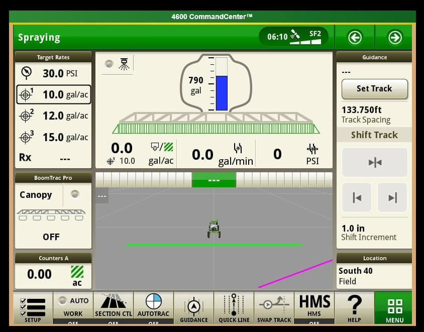
The module is a bar graph that gives you relative DCs along boom. In the first example, we’re driving straight and everything is fine. After a couple of shoulder checks, we pull out the smartphone and take a picture.
The bar graph format is useful during turn (left in this example, forcing higher DC to outside of boom, the right).
If it plateaus on outside (as in tight right turn, below), you are under-applying on the outside since the DC can’t go higher than 100%. Slow down and that improves it because it lowers the duty cycle of the entire machine.
Slowing down may cause too low a DC, resulting in over-application on inside of boom because the DC can’t be reduced below 15%.
Remember, for Turn Compensation to work, make sure the box is checked (Menu|Boom & Nozzles|ExactApply Config/Spray Mode|Manual Setup|i|<down four screens>|Turn Compensation Check box). While you’re there, make sure the “Limit Minimum Flow %” is unchecked. This lets DC go down to 15%, from 25%.
Capstan Ag brought Pulse Width Modulation (PWM) to spraying in the mid 1990s. Over the past 20 years, it has become commonplace on Case sprayers as AIM Command and AIM Command Pro, and as an aftermarket product, called Sharpshooter or PinPoint, on any brand sprayer. If you’re new to the concept, read about it here and here.
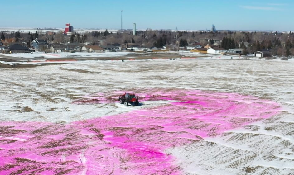
A sprayer turn, without turn compensation. Note the darker dye on the innermost nozzles and lighter deposits on the outer wing.
The latest versions (AIM Command Pro and PinPoint) offer turn compensation and individual nozzle sectional control. But there remains a large base of older AIM Command units that lack turn compensation. And of course, sprayers that lack PWM alltogether, possibly because of cost.
The Capstan EVO addresses both issues. Introduced in January of 2019, it gives older AIM Command units affordable turn compensation. As a bonus, a complete new EVO install on non-PWM sprayers is available at a significant discount compared to most other PWM products.
EVO features many of the same basic PWM capabilities as its bigger cousins, but with a shortcut, explain Capstan representatives.
As always, a change in travel speed changes the duty cycle of the pulsing solenoid, adjusting flow rate of the nozzle without a change in pressure. This provides the consistency in performance that we love about PWM. Drift or coverage are controlled by the operator who makes changes to spray pressure from the cab, with a commensurate background adjustment in duty cycle so that travel speed is unaffected.
With the EVO, the shortcut is that sectional control is by plumbed section. Technically it’s possible to add sections, but the rate controller and the sprayer wiring would have to allow it.
Spray dosage for sectional turn compensation for six sections of equal size, with the centre of each section applying the target dose. As always, some lateral movement of spray from adjacent nozzles will occur.
Turn compensation is part of EVO, and this is an important benefit that was previously only available in more expensive versions of a PWM product. Each section will have a fixed turn compensation based on the speed of the centre of the section. Its performance will depend on the size of the sections.
For a 100′ boom with six 10-nozzle sections turning around an object with a 60′ diameter, our modelling shows that the deviation from perfect turn compensation is least on the outer wings (where it’s most important) and grows towards the inside of the turn. In this example, the outer section’s end nozzle under-applies by 6% relative to the ideal, and the innermost nozzle on this section over-applies by 7%.
On the next section, these deviations are 7% under and 8% over, then 8% under and 9% over.
Moving from the centre of the sprayer to the inner wing, deviations are 9% under and 12% over, then 12% under and 16% over, and finally 16% under and 24% over.
Spray deposition on an un-compensated turn.
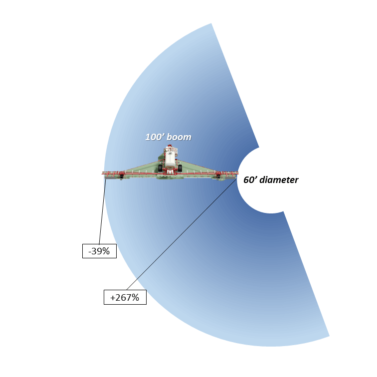
On an uncompensated boom with the same dimensions, the outermost nozzle would be under-dosing 38% and the innermost nozzle would be over-dosing by 267%.
Recall that it’s more important to be accurate on the outer wing than on the inner, for the purpose of delivering the full spray dose in a turn.
Repeated year-after-year under-dosing at the periphery of a turn such as field corners, or around permanent features such as sloughs, trees, or stone piles results in weed problems.
EVO is intended for users with an original SharpShooter or AIM Command who would like turn compensation but don’t want to a whole new PWM system. EVO provides new modules and a new screen, but users save money because they can keep their existing solenoids, says Capstan.
Capstan says that EVO is for every brand of sprayer ordered without pwm control from new to 15 years old. It’s an easy upgrade for owners of AIM Command & SharpShooter systems because these already have most of the components, and install times are therefore lower for these machines. Existing solenoids and wiring harnesses can be retained.
Owners of high clearance pull type sprayers will also see the advantage of turn compensation and pressure control at an attractive price point.
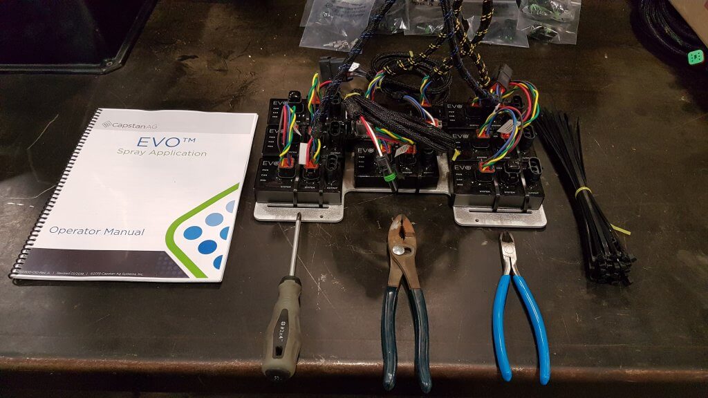
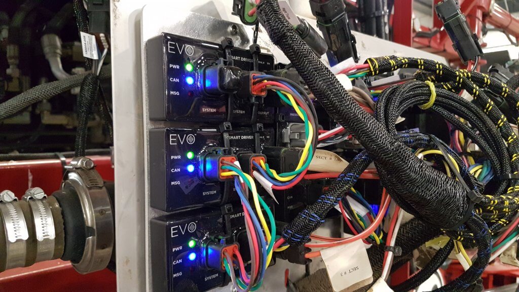
EVO modules and tools needed for installation
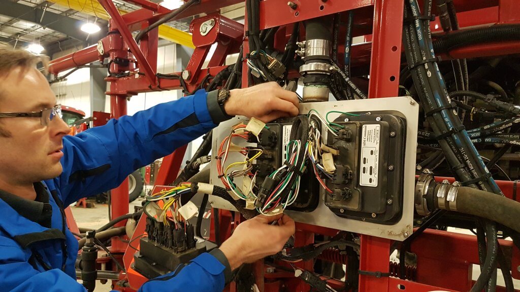
I was present during an installation of these new modules on an existing Case 3330 sprayer with AIM Command. It took one person, with occasional assistance from a second, less than 1 h to do the conversion.
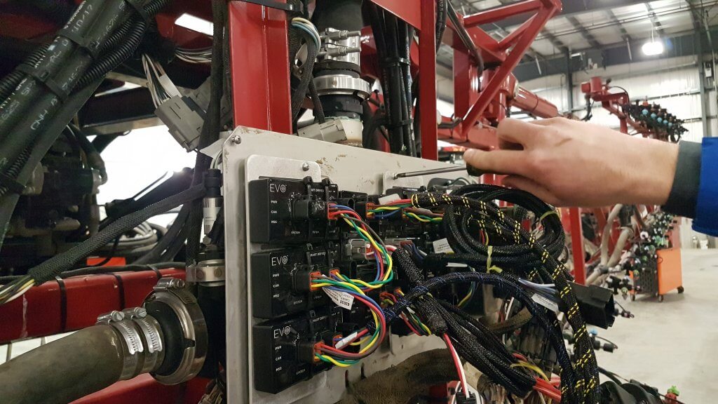
Removal of AIM Command modulesInstallation of EVO board containing all modules and replacement plugins
A new installation would require an additional several hours to install wiring harnesses and solenoids. Times will vary with sprayer model and technical experience of the installers.
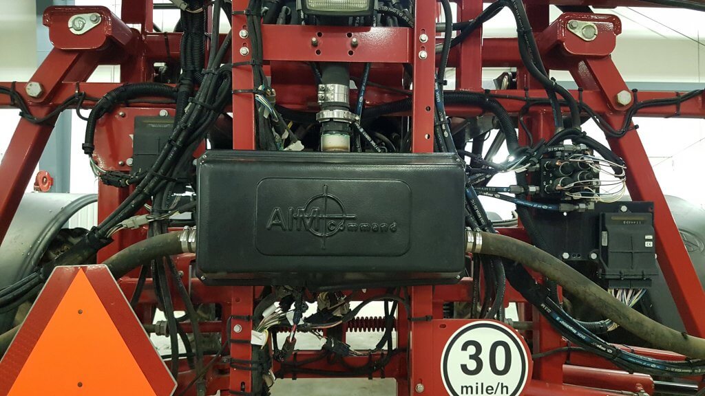
The EVO electronics run in parallel to the existing sprayer monitor. It allows the existing monitor to control sections and determine the flow requirements. It does not control pump speed, it simply reads the flow, pressure, and gps signal from the sprayer’s systems and uses them to determine the duty cycle (DC) that ensures the spray pressure remains constant. On AIM Command units, the pressure control module remains installed and pressure adjustment remains possible through AIM Command in cab controls.
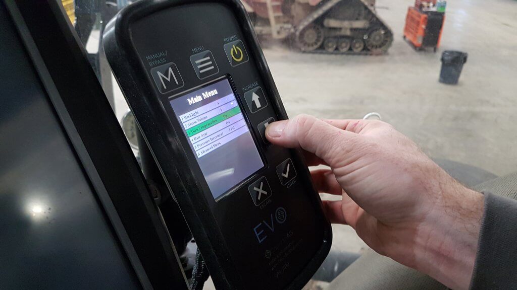
Entering system settings into new EVO monitor
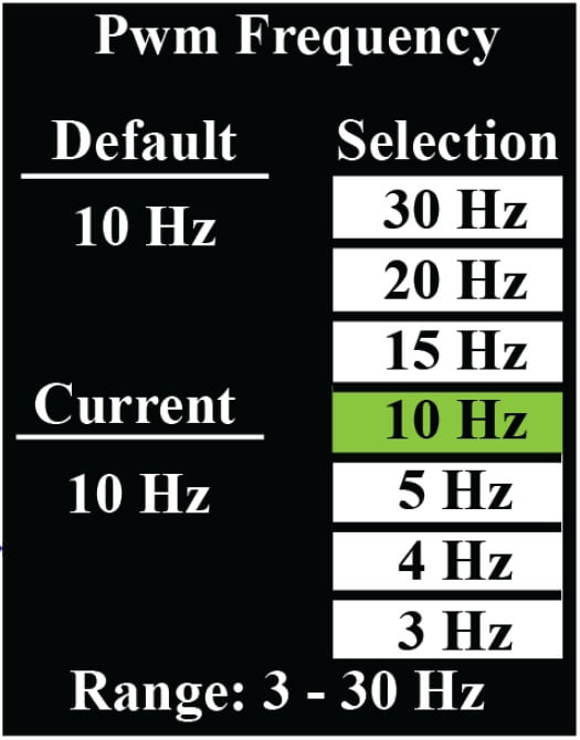
It’s possible to set the pulsing frequency between 3 and 30 Hz in EVO, an industry first. The lower the frequency, the wider the dynamic flow rate. Capstan advises to maintain a frequency above 10 Hz for spray operations. Lower frequencies may be used for fertilizer applications, where prescription maps require a higher rate range and where uniformity requirements are more relaxed.
EVO Monitor contains an option in which to select pulsing frequency
Testing of completed EVO Installation
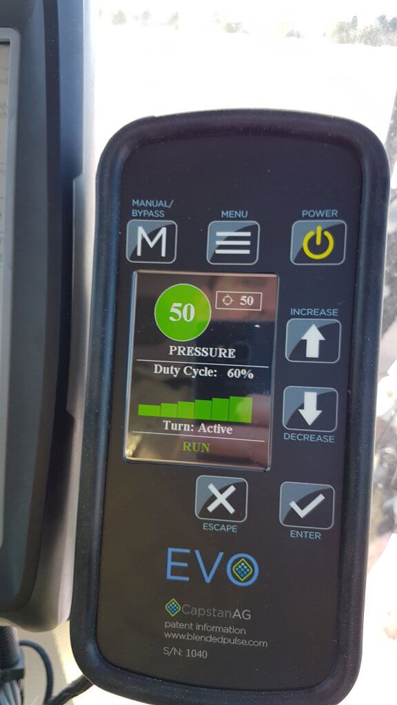
The monitor has an intuitive readout of average DC and a bar graph showing the DC across sections in a turn. If this bar maxes out on the outer sections during a turn, simply slow down to lower average DC and provide extra capacity to those sections.
EVO monitor during operation. Readout includes current spray pressure, duty cycle, and turn compensation status.
Lowering the cost of PWM makes it attractive to a new group of users. It also offers a more affordable upgrade path for owners of AIM Command or SharpShooter systems that currently do not have turn compensation.
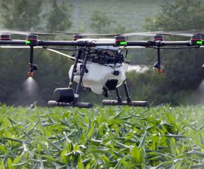
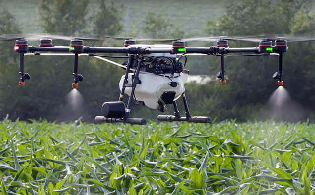
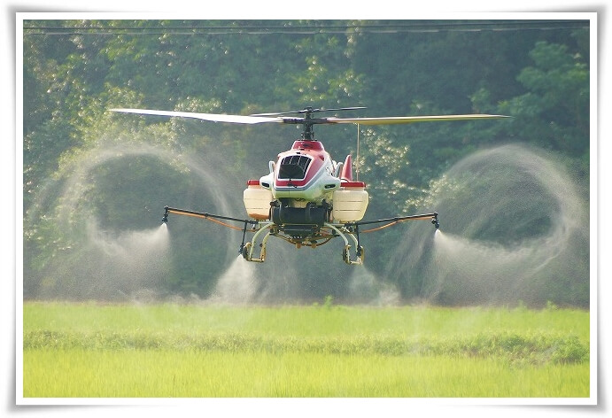
Spray application by drone is here. It’s common practice in South East Asia, with a very significant proportion of ag areas now treated that way. Estimates from South Korea, for example, suggest about 30% of their ag area being sprayed by drone. It’s in the US, too. The Yamaha RMax and Fazer helicopters, which pioneered drone spraying in Japan dating back to the mid 1990s, have been approved for use in California since 2015. DJI, the world’s largest drone manufacturer, introduced their ag model, the Agras MG-1, to North America in 2016. Many other spray drones are available or in development.
As William Gibson, the author of Johnny Mnemonic, once said,
“The future’s here, it’s just not widely distributed yet.”
DJI Agras MG-1 spray drone (Source: DJI.com)
Proponents of drone spraying cite a drone’s ability to access areas where topography is a problem, such as steep slopes, where productivity of manual application is much lower, or low areas where soil moisture prevents ground vehicles. Operator exposure is reduced compared to handheld application.
Opponents talk about productivity and cost factors compared
to manned aerial application, spray drift, and rogue use.
Before drone spraying becomes commonplace, two important
things need to happen.
Federal laws need to be updated to accommodate the unique features of remotely piloted aircraft systems (RPAS), as they’re now called. Current laws make many assumptions unique to manned ships, and the process to correct that will require some patience. A thorough review for US laws, and their shortcomings, can be found here.
Federal pesticide labels need to permit the use of drones for application. As of August, 2021, Canadian labels have no such registered use.
There is no doubt that we need to prepare for a future that includes spraying by drones. Features such as topography adjustment for height consistency and autonomous swath control are already essentially standard, and the capabilities that improve control and safety will continue to develop.
And yet I’ve been nervous about the prospect of pesticide application with drones. My primary concern is around – you guessed it – spray drift. Because a drone payload is relatively small (about 5 to 25 L, depending on the model), application volumes will need to be low to have any sort of productivity. How low? For manned aircraft with a 200 to 600 gallon hopper, 2 to 4 US gpa (18 to 36 L/ha) are the lowest commonplace volumes. The lower volumes require a Medium spray quality (among the finer sprays in modern boom spray practice) to achieve the required coverage.
It’s a simple concept: the less water is used, the smaller the droplets need to be to provide the necessary droplet density on the target. Drift control with coarser sprays requires higher volumes, and true droplet-size-based low-drift spraying can’t really happen at volumes less then, say 5 to 7 US gpa.
At 2 to 4 US gpa, a drone would be able to do perhaps 1 acre per load. While OK for spot spraying, it represents a serious productivity constraint for anything larger. There will be a push toward lower volumes, perhaps 0.5 to 1 gpa (5 to 10 L/ha). The only way these will provide sufficient coverage is with finer sprays, ASABE Fine to Very Fine, with expected problematic effects on off-target movement and evaporation. These fine droplets are also more prone to the aerodynamic eccentricities of aircraft.
Vortices from the rotor can create unpredictable droplet movement (Source: kasetforward.com)
The current regulatory models for aerial drift assessment in North America, AgDISP and AgDRIFT, are not yet able to simulate drone application. But by entering finer sprays into these models for their conventional manned rotary wing aircraft, we can see that buffer zones will be higher. Much higher. And that outcome will give pause to regulators. Failure to control the movement of a spray is, and should be, a problem.
Estimated Buffer Zones (calculated by AgDISP) for a reference rotary wing spray aircraft, using three pesticide toxicologies and two spray qualities.
Furthermore, ultra-low volume (ULV) sprays can change the efficacy of some products, and these will require new performance studies. At this time, regulators are seeking information not just on spray drift, but on product efficacy, operator and bystander exposure, and crop residues.
Regulators are currently collecting spray drift and efficacy data from drones. Since the drones available in today’s market do not conform to a common design standard like fixed or rotary winged manned aircraft, each model may have its own characteristics and need its own study. Some will have rotary atomizers, others will use hollow cone hydraulic sprays. Some will have electrostatic charging, others may propose special adjuvants.
Once data are assessed, there will likely be restrictions in flight height, flight speed, wind speed, spray quality, water volume, perhaps air temperature and relative humidity (or Delta T). This is not new to spraying, as current labels already constrain use for both ground and aerial spray application, more so for aerial.
The obvious question is how these proper application practices can possibly be assured. Operators will need more than just regulatory approval to use a drone, they will require proper training, similar to what a commercial aerial applicator now receives prior to operating a business.
Recall that our aerial applicators are governed by national organizations, the NAAA in the US and the CAAA in Canada. These organizations are in regular contact with federal regulators to assure compliance. They also help fund research into application efficacy and safety. They organize conferences in the off-season and calibration clinics in the growing season. At these, flow rates are confirmed and deposited droplet size is measured. Spray pattern uniformity is assessed and corrected as necessary.
Should drone applications be exempt from these controls? I don’t think that would be wise. Are we ready to implement them? Absolutely not.
These requirements would change the drones’ economic model. And despite these precautions, a drone may still leave the control of a pilot due to unforeseen technical or human events.
In the US, Yamaha does not sell their drone helicopters. Instead, they deploy their own teams to make the applications. This way, they have assurance that only trained and experienced pilots use the technology.
As the industry gears up for the first registrations, we see drone service companies take a leading role in testing. Much is being learned via legal applications of liquid micronutrients, for example, or limited use of pesticides under approved research permits. And I’m pleased to see the recognition of drift management in these efforts through the use of low-drift nozzles. We are off to a promising start.
Requests for drone use are in progress at our regulatory agencies. The outcomes of their risk assessments will provide important initial guidance, and food for thought and discussion. In the meantime, the drone development continues at a rapid pace, with new features and greater capacity at each iteration.
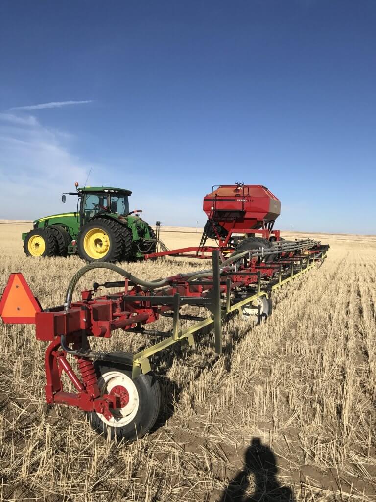
This week I spoke with Gerry Bell, a producer from near Gravelbourg in southern Saskatchewan (a beautiful town with a historic downtown, church and school, also, home of the Gravelbourger at the local diner). He told me about a project he recently completed, converting his older pull-type sprayer to a granular spreader. It’s a great project, worth sharing.
The concept was first popularized by Manitoba farmer Kyle Holman in 2012, who uses the #SprayMar hashtag on Twitter to promote it.
I will say that i do have the original #SprayMar since I did coin that, but I did not build the original pull type device. We saw 1 online after we built it but dad had been thinking of it for yrs. #WhatCouldHaveBeen
Gerry wrote his project up for us and I’ve posted his description below.
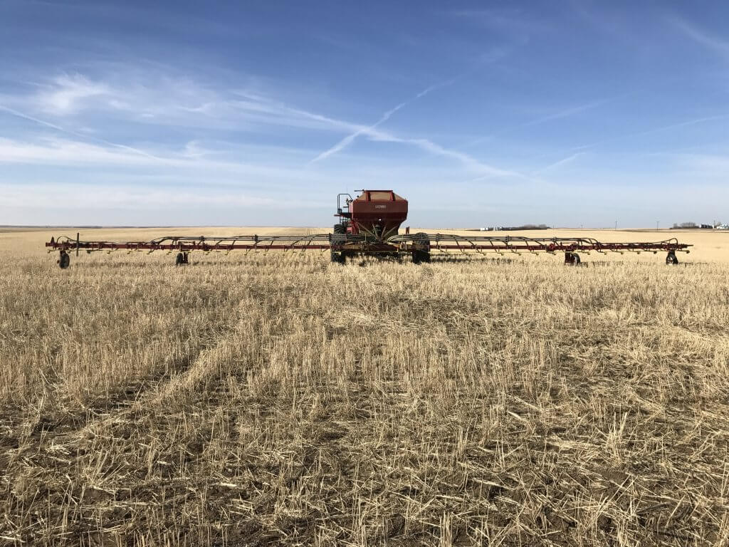
Bourgault 1460 Field Sprayer
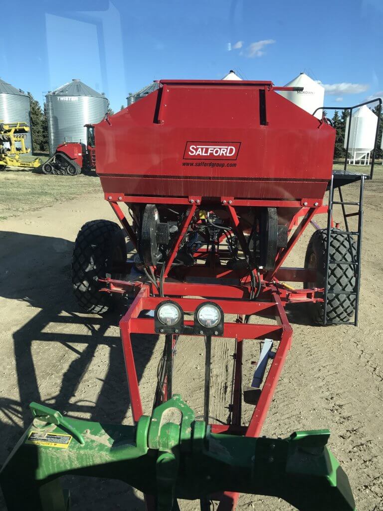
The sprayer sat in a machine shed from 2011 when we purchased a Patriot 4420 sprayer. For many years we wondered if we couldn’t find a use for the sprayer as Bourgault had build a very rugged unit. So, in 2017 we decided to mount a Valmar tank (now owned by Salford) on the sprayer frame to be used for granular herbicides and granular fertilizer applications.
Bourgault 1460 (Source: Bourgault.com)
The liquid tank and plumbing were removed as well as the
secondary boom with the wet boom. A few modifications to frame were made but
for the most part the frame was left as is. The unit was painted with the Salford
colours. (Case IH red)
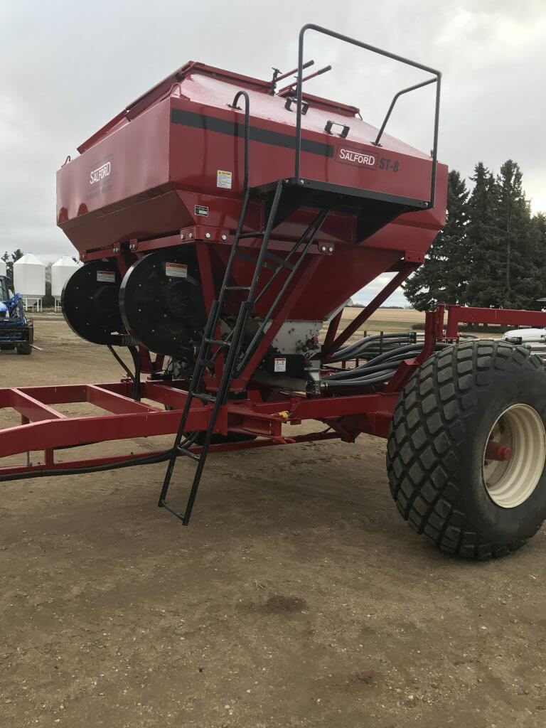
The Valmar/Salford unit is a ST8 which is used lots in
Eastern Canada and the States for strip tilling for applying granular products.
We purchased the tank, hoses, splitters and deflectors from Salford.
The unit as purchased had the following features:
8 imperial tons (16,000 lbs)
Stainless steel tank and duct systems
Mueller Hydraulic metering system with two sets
of rollers – one pair for granular herbicides and one pair for granular
fertilizers
Two hydraulic driven air fans – usually just one
fan but we chose two fans – one for each boom
Weight scales for tank
ISOBus system with mapping, auto on off,
sectional control (one for each boom)
18 outlets – 9 outlets on each side of tank
We designed unit in consultation with Salford engineers:
Each of the 18 outlets has a 2” flexible hose from the tank going to 2” stainless steel tubing stacked on the boom frame
Just prior to the deflectors each 2’ tubing is split into two 1-1/4 streams with special splitters supplied by Salford (according to Salford these are commonly used and have an accuracy of less than 2-3 % variation if mounted properly). Need to be horizontal.
The deflectors are mounted every 30” along the length of the boom (36 deflectors)
The sprayer boom was cut down from 110’ to 90’ to give the correct spacing
Comments on use of
the unit
Functionality seems to work very well as designed
Weigh scales, GPS, mapping, auto on/off, sectional control a real plus compared to original field sprayer with none of these features
Accuracy of product metering seems very good
Distribution across length of unit seems very good
Travel speeds of 10 mph
Product takes 2.5 seconds from time meter starts turning until product reaches far end of boom
There is a difference of about thirty feet in travel distance with start and stop of product on the ground between inner side of boom and outer end of boom. Therefore, we have set look ahead time at 3.3 seconds and shut of time at 0.3 seconds.
Load products with a belt conveyor in yard
Apply 100 lbs of elemental sulphur (0-0-90) on
25% of the crop land each year
(Tank does 160 acres)
Applied Avadex at 12.5 lbs per acre last fall on
some acres prior to snow.
Apply Edge at 20 lbs per acre each fall just
prior to snowfall (for pulses)
Tanks holds 10 minibulk bags – 12,000 lbs, and does 600 acres. On a long day have put out 1200 acres of Edge.
We did extend the axles and also put on new hubs and new tires which were a bigger size. A Bourgault 1850 with 1600 gallons would have worked better but it is hard to find them. Plus they would probably have needed new tires anyways.
It took a lot more time than we had imagined to build but that is true of most building projects. But I would say that we are very happy with the results. It is a pleasure to operate and appears to serve our needs very well.
Listen to an audio recording of this article by clicking here
There’s a lot of talk about lowering the boom to reduce drift and make twin fan nozzles more effective. But how low can we actually go with a boom before striping becomes a problem?
We’ve done some calculating and have come up with answers.
First, a few guidelines. Tapered flat fan nozzles require overlap to generate a uniform volume distribution under the boom. Traditionally, we’ve recommended 30 to 50% overlap with fine flat fan sprays. The small droplets tended to redistribute to fill in any gaps that might occur.
Overlap from fine sprays is less critical than from coarser sprays because the small droplets redistribute readily.
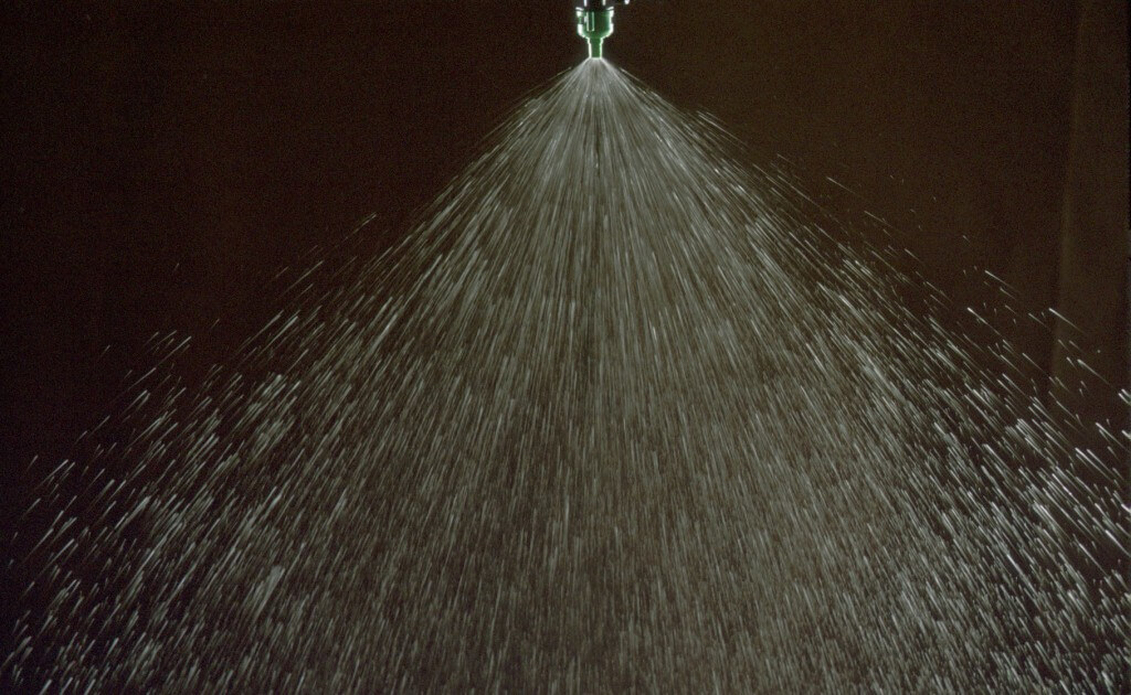
The advent of low-drift nozzles changed that advice. This nozzle type produces fewer droplets overall, and, like all fan-style nozzles, puts the coarser ones towards the outside edges of the fan. These don’t redistribute.
A typical flat fan spray places the coarser droplets at its periphery, and the smaller ones in the middle. When only the outed edges overlap, that can creates a band of poor coverage.
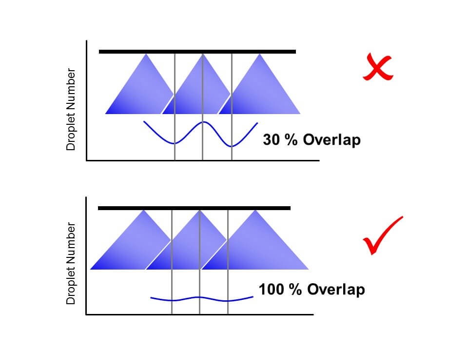
When we had 30% overlap and these two edges met, a region of relatively few, coarse droplets was formed, and this region contained almost no small droplets. On a patternator, the volume distribution was still good. But when we measured the droplet density, we saw a deficit in coverage at the overlap.
With low-drift nozzles, we need 100% overlap to distribute both small and large droplets uniformly under the spray swath. Too little overlap and we create bands of relatively few but large droplets that can cause striping.
Since then, we’ve been recommending 100% overlap for low-drift sprays. This means that the pattern width at the target will be twice the nozzle spacing, and all regions under the boom receive droplets from two adjacent nozzles.
With this adjustment, small droplets appeared throughout the spray swath, and striping was eliminated.
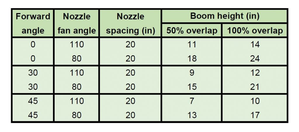
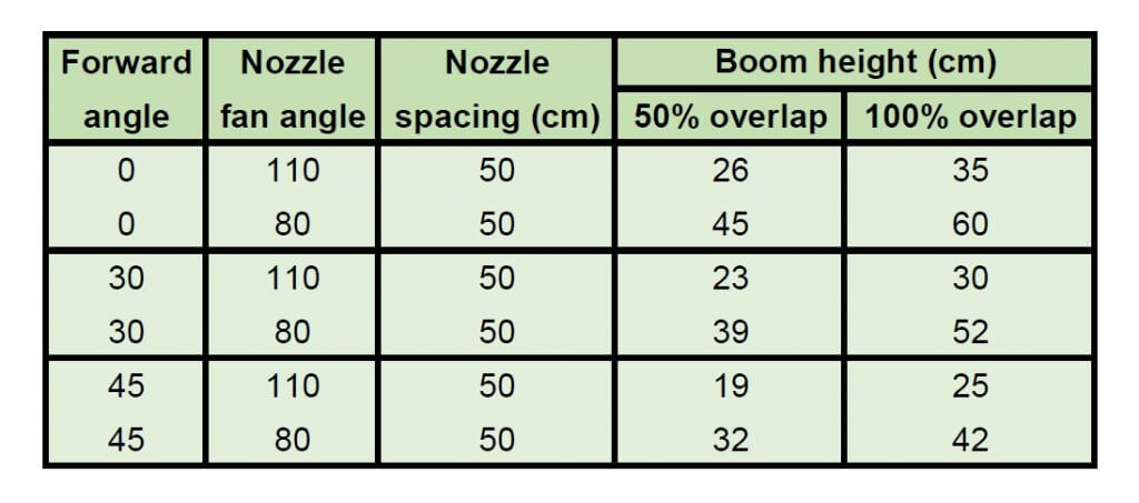
That leaves the question, just how low can a boom be set without creating this problem? The following tables provide some theoretical numbers.
Minimum boom heights for achieving 50% and 100% overlap of flat fan spray nozzles (US units) Minimum boom heights for achieving 50% and 100% overlap of flat fan spray nozzles (metric units)
A word of caution: The advertised fan angle on a sprayer nozzle often differs in practice. Not only will it be slightly different by design, it also depends on spray pressure and tank mix. As a result, it’s best to do a visual check. Set the spray pressure to the minimum you expect to use. Inspect the spray patterns and set the boom height so that the edge of each nozzle pattern reaches to the middle of the next nozzle. That means your pattern width is twice the spacing and will give 100% overlap. No tape measure required.
The tables were generated from a spreadsheet which can be downloaded here:
The values are theoretical and assume the fan angles are accurate. Some nozzles don’t produce the advertised fan angle. Enter your actual angle in the spreadsheet if you know it.
The theory assumes that the droplets at the edge of the fan always move in their projected direction. In fact, after some distance, say 50 to 75 cm, gravity pulls the droplets down and the pattern no longer widens at the same rate. The rate of pattern collapse depends on the droplet sizes.
Use the 0% overlap column to help with banding nozzle pattern width. Simply use the nozzle spacing column to enter your desired band width.
Note that angling the nozzles forward or backward decreases your minimum boom height, but depending on the deflection of the spray in the wind, this too has limits.
Too high a boom obviously increases drift. But patternation from overlap isn’t affected that much, largely because the pattern is now subject to aerodynamics and that becomes more important.
Pro Tip: Attach a length of plastic hose or a large zip tie to the boom, cut to your minimum boom height. This makes it easier to see what your boom height is, from the cab or the ground.
The bottom line is that a boom can be quite low and still allow excellent overlap and pattern uniformity from the nozzles. Yet we all know that most sprayer booms can’t reliably operate that low because they don’t control sway well enough. The ball’s in your court, sprayer manufacturers!