Category: General Operation

All general hort articles on sprayer operation.

  • Top Sprayer Retrofits

    Top Sprayer Retrofits

    You’ve got an older sprayer. Your neighbours have newer sprayers. For various reasons, you’ve decided against a trade.  How can you still get the benefits that newer sprayers deliver? Let’s explore how to improve your sprayer performance and productivity with strategic component upgrades.

    Most of the biggest gains will relate to the plumbing, especially filling and cleaning. Here is a list to think about:

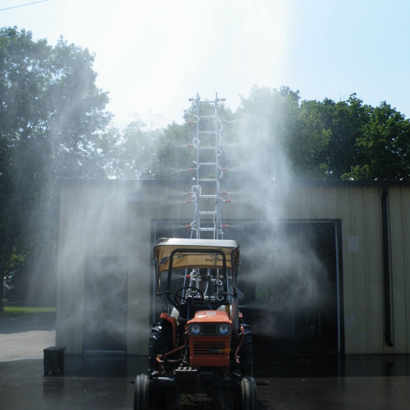
    Nozzles.  This one’s a no-brainer. Nozzles remain the cheapest and most important part of any sprayer, affecting coverage, drift, and accuracy.  Although durable, nozzles do wear or get damaged over time.  But perhaps more important is the changing use patterns of our pesticides.  We are moving into a time of greater reliance on tank mixes that blend systemic and contact products, and also higher water volumes into mature canopies.  For example, fungicides for Fusarium Head Blight benefit from twin fan nozzles. We’re also seeing new herbicide registrations with greater spray quality (droplet size) restrictions, requiring coarser sprays or higher water volumes to maintain acceptable drift amounts. Are your nozzles able to meet those needs?

    Nozzle bodies or turrets. As we move towards more specialty applications, perhaps we need a greater selection of nozzles at our disposal at any given time.  Bodies with 5-nozzle turrets are standard on newer sprayers, and these make sense. Burnoff, in-crop, fungicide, and fertilizer nozzles are four that most users will need just from flow-rate needs alone.  But some finer or coarser options of each may also be justified, and easy access saves time in the field. New bodies also provide new seals, and the newest offer higher flow rates and exchangeable parts.

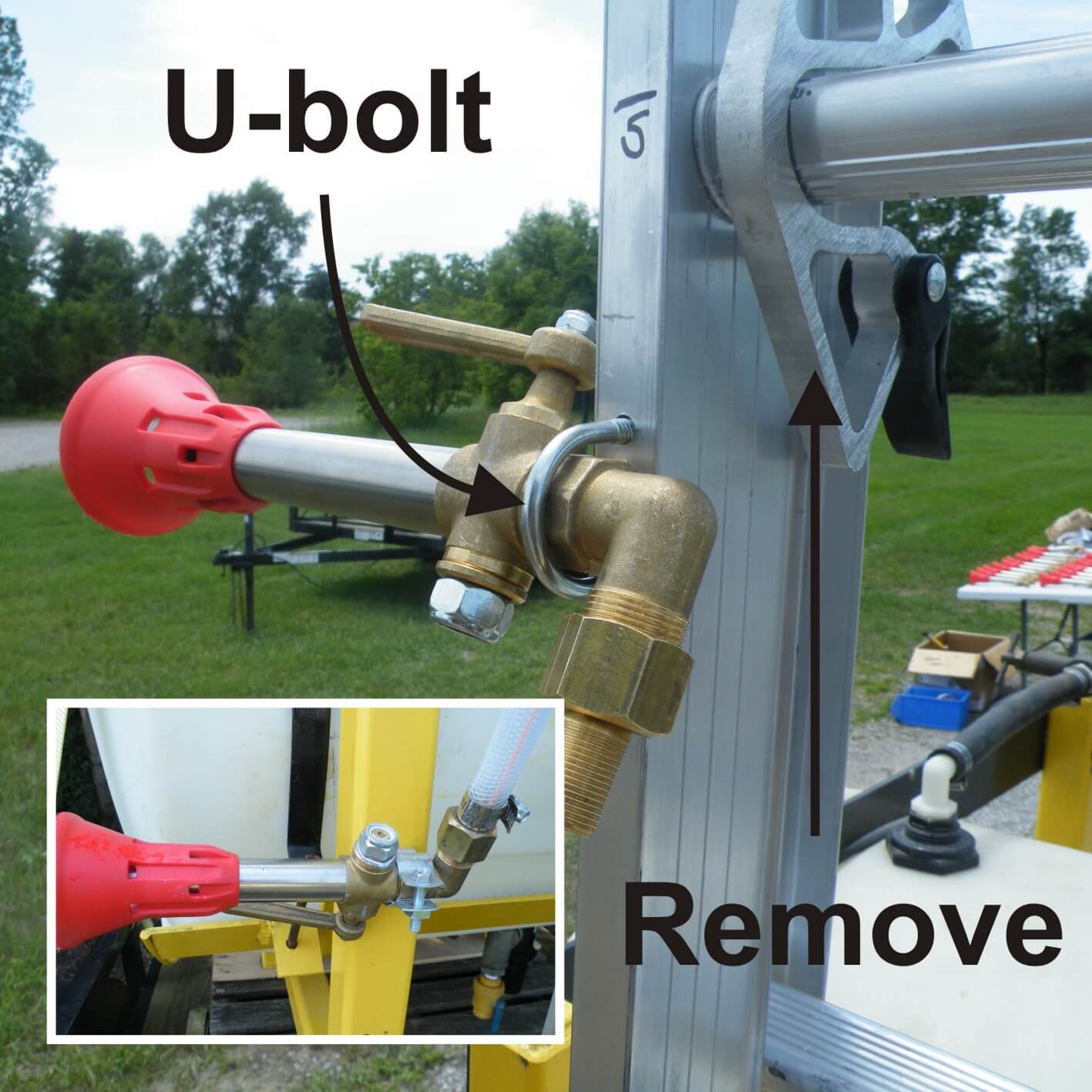
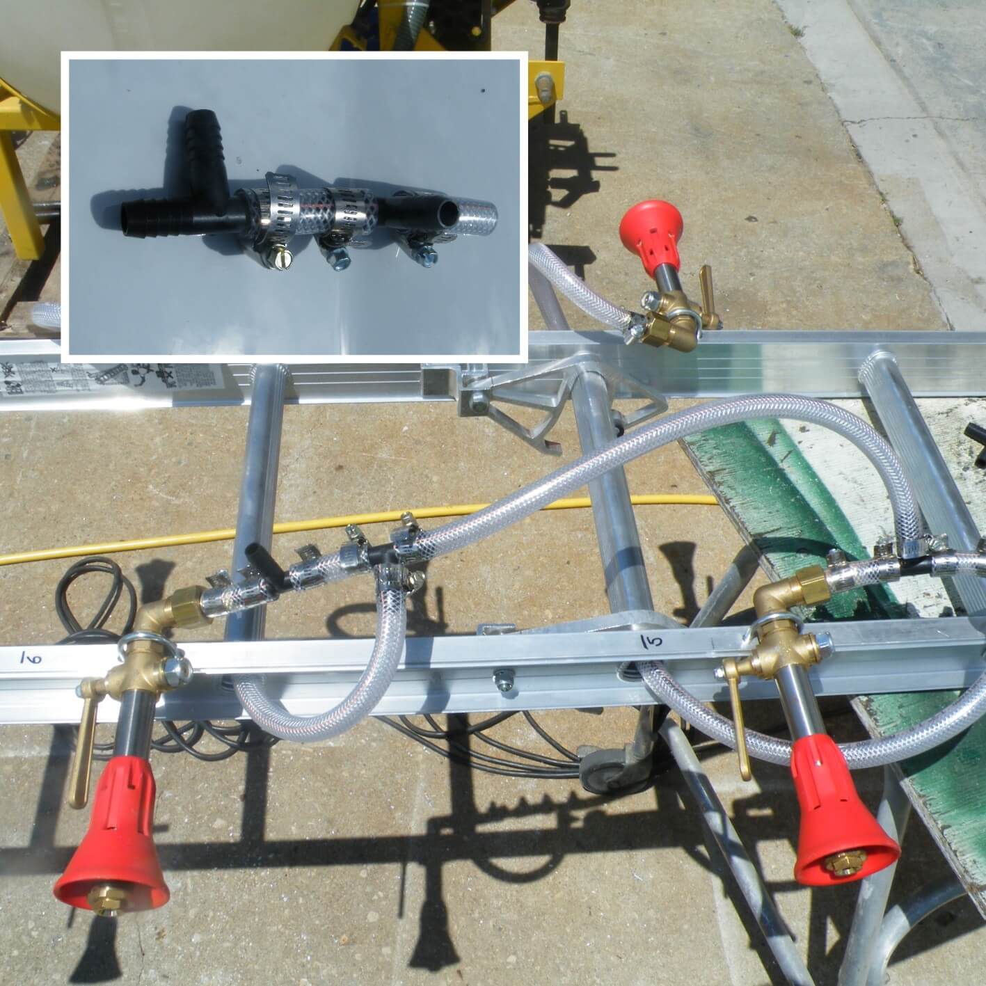
    Boom end cleanout.  Removing residue or air from booms is an important part of good practice.  Many sprayers already have manual valves that allow this to happen relatively easily, but it’s still a process that an operator has to make time for.  And on top of that, flushing boom sections results in massive doses of pesticide on the soil.  One of the most innovative inventions in recent times is Hypro’s Express Nozzle Body End Cap.  A DIY or dealer installation of these units allows your boom to bleed introduced air on the go.  The ENBEC also forms a dead end exactly at the last nozzle position, eliminating the dead spots that introduce contamination after a pesticide switch.  Cleanout and shutoff response also improves.  A fast boom flush is straightforward by moving the turret to an open position.  TeeJet offers a Rapid Stop extended inlet tube that evacuates trapped air from the wet boom, can be retrofitted on most bodies. Wilger Combojet bodies offer a similar design called Kwikstop. Both can be expected to improve shutoff response, but do not address boom end contamination.

    Wet boom. Are your wet booms made of plastic? If so, they can warp over time and are also harder to clean.  Replacement wet booms are available from several suppliers, including Hypro and Wilger.  These are made of thin-walled stainless steel for excellent durability and ease of cleaning. Wilger units are very thin and light and come with their own Quick-Nut fittings and feature swept elbows and Ts.  Hypro’s Express Booms come with nozzle bodies and Express Nozzle Body End Caps. Flange fittings are used in the Hypro upgrade.

    New boom. Some people are recognizing the value of boom width in sprayer productivity and are considering a wholesale boom replacement from a third party.  These booms come in wider sizes, lighter materials such as aluminum or even carbon fibre, and innovative plumbing options such as recirculating designs or telescoping for adjustable widths from 80’ to 150’. Perhaps a better suspension system or automatic boom levelling system is part of such a purchase.

    Individual nozzle shutoff. Most sprayers have sectional control of at least 5 sections. But some of the outer wings (the part of the boom that is most often involved in sectional control) can still contain significant lengths tied to a section, creating waste. With individual shutoff valves, a boom can be converted to either many smaller sections or even nozzle-by-nozzle sections, depending on the capabilities of the rate controller.  Not only do these offer excellent resolution, they also feature instant shutoff and turn-on response at the spray pressure.  Because this type of installation can demonstrate product savings, it has a calculable ROI.

    Rate controller. Some older sprayers struggle with responsiveness. An operator changes speed, and has to wait a long time for the rate controller to catch up.  A newer controller can improve the responsiveness significantly, offer a new larger cab screen, work better with a navigation system, or even include ISO-BUS capabilities for future upgrades.  Improving the user experience with a better interface can be valuable, giving an old sprayer a new capabilities and feel.

    Variable rate technology. We are seeing several options that can offer better control over nozzle flow rate to suit either a greater range of travel speeds (on hilly or otherwise uneven land) or a better range of rates for prescription map application.  Pulse-Width Modulation systems from Capstan (Sharpshooter) and Case (AIM Command), Raven (Hawkeye), or TeeJet (DynaJet) all offer these types of features.  A new nozzle body, Hypro Duo React, achieves similar results with multiple nozzles that can switch back and forth according to flow rate needs.

    Boom lights. Whether spraying at night or wishing to see spray patterns better in the day, boom lights can help. Versions are available from ATI or SprayTest. Caution is advised when spraying between evening and morning hours, as temperature inversions are common during that time.

    3″ plumbing. One of the biggest productivity tools is decreasing the time required to load a sprayer.  Wide booms applying large water volumes at fast travel speeds can empty even a large tank in 30 minutes or less. If the fill also takes 30 minutes, then 50% of the spray day is spent idle just for filling.  Increasing the fill speed with a new load system using 3” plumbing and a high capacity pump can reduce that to 10 minutes, adding acres per hour.  Make sure, though that dry products are properly hydrated so they mix well and stay out of screens. Also consider the rate of chemical induction, as that can be a bottleneck.

    Tank wash down nozzles. These nozzles, installed at the top of the tank, direct a clean water source (containing a cleaning adjuvant if needed) to the tank wall, rinsing the pesticide off. Successive batches of cleaning improve the tank wall decontamination as the solution becomes more dilute.  By making the wash down easier, tank cleaning can occur in the field immediately after spraying and the rinsate can be sprayed out in the field.  This saves time and prevents point-source contamination.

    Self-cleaning line strainers. Consider this a productivity tool.  Mounted on the pressure-side of the pump, these strainers use excess pump capacity to bypass particles back to the tank.  A tapered design creates a rapid flow of liquid past the screen face generating continuous wash-down of particles. Regular inspection is still recommended, but the chance of a problem is significantly reduced. Because debris is returned to the tank, proper tank sump cleaning becomes more important.

    Pump.  Some call it the heart of the sprayer. The pump pressurizes the spray mixture so it can be distributed evenly and atomized.  To do this, it needs to produce high enough flow for our ever increasing water volumes, travel speeds, and boom widths, while maintaining enough reserve for agitation. Some use the system pump to draw water into the tank, which can present a bottleneck.  Clearly, capacity and pressure are important.  Pump impellers can wear and seals can leak, reducing performance. New or re-built pumps are available in long-lasting stainless steel, and the best new models have flange fittings and seals with either enhanced dry-run survivability, or dry-run capability. An upgrade definitely worth considering.

    Clean water tank with dedicated clean water pump. This is another productivity tool. Cleaning the tank in the field without stopping the sprayer becomes an option with this design. Rather than use the product pump to draw clean water into the tank, mix it up, spray it out, and repeat, this design allows continuous cleaning. When the product tank is empty (signalled by a loss of pressure), the clean water pump turns on and delivers clean water through the wash-down nozzles. The pump must have enough capacity to obtain a good cleaning spray from the wash-down nozzles. As the sump fills again, the product pump delivers it to the boom and also cleans the return lines. The end result is prompt cleaning of the tank and thorough, efficient dilution of the remainder.

    Boom remote control. Whether it’s for cleaning out boom ends or simply verifying proper nozzle operation, a remote boom section shutoff makes those jobs easier, safer, and more environmentally friendly. Boom remote controls let you turn on just the boom section you need to inspect. It’s also useful for nozzle calibration.

    Tires. Ask yourself: what equipment do I spend more time in than any other, makes more passes over each field than any other, makes deeper ruts than any other, and gets stuck more often than any other?  A new set of tires, or even tracks, might be worth considering. Low-pressure sprayer-specific tires with VF (Very High Flexion) technology are available from major suppliers. These offer sprayer-specific lug designs, they increase the footprint for increased floatation and less compaction, and they can also improve ride quality. Tracks, though considerably more expensive, are becoming available for sprayers and can make sense in some situations.

    Some of these retrofits can be costly.  But they can introduce new life and utility into an aging chassis, resulting in higher productivity, higher quality work, or simply a better operator experience.  All of these are important and are worth investing in.

    Here’s a Real Agriculture video of Tom and Jason talking sprayer retrofits at the end of Edmonton’s 2016 FarmTech.
    Note the snazzy “Sprayers101” team shirts!

  • Hydraulic Fittings: A Galling Metallurgical State of Affairs

    Hydraulic Fittings: A Galling Metallurgical State of Affairs

    So it’s been a long spraying season and as you perform your annual maintenance you grudgingly admit that the hoses have given their all. Before you run out to get more of the same, give some thought to the hydraulic fittings (i.e. hose adaptors and couplers). Many feel that stainless steel (SS) is the best choice for hydraulic fittings: It must be, because it’s certainly the shiniest and most expensive choice! But before you opt for stainless, here are a few things you should know.

    SS requires surface oxidization to resist corrosion. Oxidation forms a protective barrier called a “passivation layer”, but it’s susceptible to mechanical damage. It can be penetrated as abrasive powders flow past. The layer will reform when it dries, only to be sanded off again during the next spray. The wear is on-going. If the newly-exposed SS remains submerged in a liquid, the passivation layer will not reform. Without it, SS surfaces corrode at a high rate, and in extreme cases SS will even corrode inside of itself and become a hollow shell.

    When two pieces of stainless steel are forced together, the passivation layer gets scraped off, allowing parts to gall (or ‘weld’). In fact, any similar metals in physical contact will naturally gall to each other, but stainless steel is especially susceptible. When disassembled, the ‘welded’ material must be torn apart. This destructive galling can be reduced with lubrication during assembly and avoided altogether by mating dissimilar materials (e.g. bronze and stainless steel). Technically, mating different types of stainless steels (e.g. martensitic against austenitic) could work, but it is possible that two different alloys electrically connected in a humid environment may act as a voltaic pile and corrode even faster. This is probably a moot point because many do not have access to different SS alloys when choosing fittings.

    Sometimes we see black or galvanized pipe fittings on sprayers, but I don’t recommend either. Galvanizing is only slightly better than black pipe and since the threads are cut after being galvanized the threads are essentially black pipe, anyway.

    So what about plated steel fittings? They’re available with swivels and can seal on faces and seats (rather than on the thread – which is much easier to assemble and disassemble). They can be crimped onto the hoses, eliminating the need for hose clamps that fail or snag and cut the operator. (As a related aside, hydraulic hose is not really compatible with most spray products – the steel wire inside the rubber begins to corrode and unexpected failure is common. Even when spraying above 200 psi there are better high pressure-rated choices than hydraulic hose.) Mechanically, these fittings are a great option, but unfortunately the plating is designed for oil, not pesticide. Within a year they rust internally and seize up. To add insult to injury, the flaking rust is notorious for plugging nozzles.

    A better choice is brass (or even bronze) fittings (e.g. pipe, SAE 45° and hose barb). Just like the crimped plated steel fittings, brass SAE 45° fittings can swivel and seal on seats and they are easily assembled and disassembled over many seasons. Brass fittings are more costly than black or galvanized pipe but cost less than hydraulic or SS fittings. Conveniently, they’re available at most hardware stores.

    While brass may be the best metal material for the sprayer fittings, I feel that plastic is the most economical and in many applications is superior to metal. But, that’s a topic for a follow-up article. So, before you spring for SS hydraulic fittings, consider cheaper and more effective alternatives like brass or plastic. And, if only for the sake of your mechanic, please don’t over tighten fittings. It is unnecessary and causes endless damage and frustration.

  • Exploding Sprayer Myths (ep.3): Nozzle Pressure

    Exploding Sprayer Myths (ep.3): Nozzle Pressure

    Here’s the third in our series of short, educational and irreverent videos made with Real Agriculture.
    We wanted to explain where pressure readings are taken on a sprayer and why it’s so important to know what pressure your nozzle is experiencing, rather than what the screens in your cab are telling you. Not only does pressure affect your application rate, but it affects your spray quality, which can be critical if your rate controller allows the pressure to drop below 30 psi.

    IT’S MY TURN TO DRIVE!

  • Exploding Sprayer Myths (ep.1): Rate Controllers

    Exploding Sprayer Myths (ep.1): Rate Controllers

    This is the first of a series of short, educational and irreverent videos made with Real Agriculture to bring a little levity to sprayer education. Let’s face it – ironically, nozzles can be pretty dry.

    This first video discusses what a rate controller can be expected to do, and what it cannot do. Plus, we got to blow up a sprayer in the intro… so there’s that.

  • Experimental Hops Sprayer

    Experimental Hops Sprayer

    First, a warning…

    In 2013, when this sprayer was constructed, Ontario’s hops acreage was expanding for the first time in many years. While there were a few large operations, most were small acreage hobbyists and part-time hops growers that did not have any experience spraying the crop. The latter operations recognized a need to spray, but couldn’t justify investing in an expensive (and complicated) airblast sprayer.

    In response, we set out to design a budget-conscious, low-capacity, tower-style sprayer that small-acreage growers could build for their own operations. Our hope was that hydraulic pressure would give droplets sufficient momentum to cover all foliar surfaces, thereby eliminating the expense of an air-assist fan. Additionally, the telescoping tower would allow the operator to match the height of the crop canopy as the season progressed, reducing the amount of wasted spray mix.

    Unfortunately, the results of our spray coverage trials indicated that while the upper-face of leaves received excellent coverage, the under-side received only sparse coverage. We were unable to move the trials beyond spray coverage and into the efficacy stage, and because of this, we do not know if the under-leaf coverage would be sufficient to control sucking insects or diseases with contact products.

    So why publish this article? The principles behind the design, construction, and testing of this sprayer are still valuable. It led, in part, to growers attempting to modify older and inefficient airblast sprayers to duct air through homemade towers (see here). But, be advised that without efficacy data, we must recommend that budget-conscious and/or small acreage hop growers explore the use of gently used, conventional airblast sprayers.

    Introduction

    Hop bines are trained around twine lines and grown an average 5.5m (~18ft) high. Each line supports two or more bines and, when mature, the line becomes a dense column of foliage as much as 0.5m (~2ft) in diameter. Hopyards, both organic and conventional, use radial airblast sprayers to apply products to the foliage. However, the profile of the radial airblast boom does not match the profile of the target crop. The nozzles at the top of the sprayer have to spray a target 5.5m (~18ft) away, while those at the side spray a target 0.5m (~2ft) away. Additionally, the air from the fan must be calibrated to carry the spray to the highest point on the hop bine, which means it is excessive for the length of bine directly adjacent. With this in mind, it was theorized that a more efficient sprayer design would feature a vertical boom to position each nozzle as close to the target as possible.

    We would build “the Hopsprayer”.

    Rears airblast sprayer tackling 16-20 foot bines. Photo credit - D. Groenendale, Washington
    Rears airblast sprayer tackling 16-20 foot bines. Photo credit – D. Groenendale, Washington

    Beyond the obvious requirements of operator safety and being mechanically sound, the design and construction of the Hopsprayer was guided by four principles:

    1. The Hopsprayer should be less expensive than a conventional 3-point hitch airblast sprayer or small trailed airblast sprayer, making it cost-effective for Ontario’s small-acreage operations (~$4,000.00 CAD).
    2. The Hopsprayer should be constructed of over-the-counter parts that require minimal modification and no special machining or tools to assemble.
    3. The Hopsprayer should have the capacity to operate in the same conditions as an airblast sprayer (i.e. moderately uneven terrain, reasonable ground speeds, and through any configuration of hopyard trellising).
    4. The Hopsprayer should achieve comparable or better spray coverage along the entire length of the hop bine, both on the upper and lower surfaces of the leaves.

    Key Structural Components

    In order to make construction as simple as possible, it was decided to build the sprayer from a commercially-available three-point hitch horizontal boom sprayer. After removing the horizontal boom, several concepts were examined for mounting nozzles on a dynamic vertical boom. The key requirement was that the vertical boom could be raised incrementally, and nozzles activated sequentially, to match the height of the hop bine as it grew taller over the growing season.

    The boom itself went through several redesigns, each dismissed for reasons of excessive weight, lack of structural stability, or concerns about operator safety when raising and lowering (or even folding and unfolding) the boom. Finally, it was decided to use a commercially-available 6m (~20ft) sliding aluminium ladder. This had the advantage of being strong, light, easy to mount, and the hollow rungs were ideal for running spray lines from one side of the boom to the other. Plus, with the addition of a marine hand winch, the ladder could easily be extended to any height.

    Regarding the nozzles, several nozzle bodies and tips were considered, but the Arag Microjet had several advantages over conventional nozzle-body-and-tip configurations. The Microjet has a mixing valve built into the nozzle body which allows the operator to turn individual nozzles off, as well make minor changes to the spray quality emitted from each unit. Further, the brass nozzle body bends 90° before terminating in a threaded male connection, ideal for fixing to the ladder and attaching spray lines.

    From this point, it was a matter of positioning the key components and finding appropriate mounting hardware.

    Construction

    1 – Removing horizontal boom from three-point hitch sprayer

    (~$2,000.00 CAD for new sprayer)

    Costs vary depending on the sprayer, but the sprayer should feature a pump capable of 200 psi, a minimum capacity of 100 US gallons and a chassis that wraps around the tank to provide a sound surface in the rear for mounting he ladder. Removing the existing boom is a simple matter of disconnecting the feed line and using a set of wrenches to unbolt the boom itself.

    Horizontal boom sprayer
    Horizontal boom sprayer

    2 – Fitting the vertical boom (ladder)

    (~$200.00 CAD for ladder, pipe and fasteners)

    A 6m (20ft) ladder will not actually extend 6m because an overlap is required between the two lengths for stability. However, when mounted to the sprayer it will achieve a final height of 5.5m (~18ft) off the ground. Cut two lengths of black pipe with a diameter that just fits in the hollow rung (~½”) to a length that spans the chassis at the rear of the sprayer. Centre the ladder, punch, pilot and drill holes through the pipe and the sprayer chassis (take care not to hit the poly tank) to mount the ladder using bolts, lock washers and nuts.

    Dry-fit the vertical boom
    Dry-fit the vertical boom

    3 – Preparing to mount the nozzles

    (~$1,000.00 CAD for 12 Arag Microjet nozzle assemblies)

    Remove the ladder and separate the two lengths. Remove the two latches that lock the ladder when it slides. We mounted nozzles every 45cm (at each rung) but that was too many. Consider mounting nozzles every second rung (~90cm). We mounted the nozzles with 9/32” U-bolts but hose-hangers only require one hole and can be swiveled to position the nozzle. This is how the bottom four nozzles were attached to the chassis (see inset), not the ladder. The ladders must be able to slide past one another and the valve handle must be unobstructed.

    Dry-mount a nozzle (hose-hanger in inset)
    Dry-mount a nozzle (hose-hanger in inset)

    4 – Grinding and mounting the nozzles

    (~$100.00 CAD for mounting hardware and grinder disc)

    Remove the dry-fitted nozzle. Centre-punch and drill all the holes for the U-bolts (or preferably, the hose hangers). Remove the threaded swivel from each Microjet. Use a hand drill set to low with a Robertson bit, and an angle grinder to carefully remove the thread and taper the tip to accommodate a ½” hose. Be aware: eye protection is imperative and the brass will get hot. Replace the cool swivels and mount all the nozzles on the ladder. Use washers and set them so the hex-nut on the nozzle body is flush against the aluminium ladder.

    Removing thread from brass swivel
    Removing thread from brass swivel

    5 – Plumbing the sprayer

    (~$75.00 for hose, $20.00 CAD for Tee’s, $75.00 CAD for hose clamps)

    The plumbing on the sprayer is not complicated, but takes thought. It will require 11 ½” TeeJet T-junctions and roughly 60ft of ½” braided, clear spray line rated to 200 psi. You will also need 8 hose clamps for each set of nozzles for a total of ~50 (get extras). Using hose cutters, cut appropriate lengths for a single set of nozzles and use them as a template for the rest. Pass the line through the rungs and do not make loops too tight. Use a drill with a ratcheting chuck to ensure each hose clamp is tight.

    Plumbing the nozzles
    Plumbing the nozzles

    6 – Mounting the winch

    (~$125.00 CAD for winch, cable, clamp, angle iron and plate)

    This step is sprayer-specific. Find a spot on the chassis that you can mount a length (or two lengths) of angle iron to house the winch. On the prototype we included a sheet of plate iron to make the mount as stable as possible. Be aware that the handle (and user’s knuckles) must not hit any part of the sprayer when turning. Never let go of the handle without setting the lock, or the boom will drop and the handle will spin out of control.

    Mount the winch
    Mount the winch

    7 – Raising and securing the boom

    This will take two people. Slide the two lengths back together and raise the boom into position. Bolt the boom into place (see Step 1). Take a ½”, 8ft length of galvanized conduit and crush 2” of one end in a vice. Punch a divot and drill a hole in the crushed end. Repeat with a ¾” length of conduit. Attach the ½” inch length to the chassis and the ¾” length to the top of the bottom boom, telescoping the two lengths together. Now you have a support that is the right length, you can screw the two lengths together and repeat on the other side. Remember not to tighten one side completely before the other is in place.

    Strut attached to boom and chassis
    Strut + boom & chassis

    8 – Tie in plumbing and winch cable

    Attach the cable to the winch, pass it through the pulley on the top boom and clamp it to the lowest rung. Pass the cable between the booms. This is also how the two lengths of boom are plumbed together: A long length of hose hangs from the bottom-most nozzle on the top boom, tied to the top-most nozzle on the lower boom. All the excess hose (needed when the ladder is fully extended) hangs between the two ladders. Trust me – this makes more sense once you do it.

    Nozzles suspended on drop arms
    Nozzles on drop arms

    9 – Test the plumbing

    (~$150.00 CAD for PTO shaft)

    Finally, the sprayer must be attached to a tractor via the 3-pt hitch and PTO shaft. Ensure the sprayer is plumb and level or the boom will bounce and sway excessively as you drive. Raise and lower the boom via the winch to ensure it moves smoothly. Bring up the rpms on the tractor and engage the boom at 100 psi. Look for any leaks. Bring it up to 200 psi and drive the sprayer around with boom fully extended. Repair any blown lines. You are now ready to calibrate your new sprayer.

    Test the sprayer plumbing and stability
    Test the sprayer plumbing and stability

    Calibration

    Classic Arag Microjets will emit approximately 1 US gallon per minute at 200 psi. However, the position of the mixing valve will affect both the spray quality and rate of the nozzle. As such, a timed output test should be performed on each nozzle. Bring down the boom, fill the sprayer with water, bring it up to operating pressure and begin spraying. Adjust one nozzle until you achieve the desired pattern. Then, using a telescoping paint roller handle to reach the highest nozzles, place all valves in similar positions. Using a collection vessel, determine how much volume is emitted at a given pressure and valve position in one minute – this is a timed output test. You can find rates and valve settings for these nozzles in this ginseng article.

    Evaluating Spray Coverage

    There are two ways to evaluate spray coverage:

    1. The amount of the surface area covered (e.g. 25%)
    2. The droplet density (i.e.. the number of drops per square centimetre)

    They are not the same thing. For example, one massive droplet covering ½ the target would leave a lot of space uncovered, and therefore lots of room for an insect to walk past and never touch it. However, an even smattering of small droplets, still covering ½ the target are better because they are distributed evenly and odds are, will hit a pest.

    The Hopsprayer was trialed at Clear Valley Farms, Nottawa, Ontario. Water sensitive paper (which turns from yellow to blue when contacted by spray) was clipped every three feet up to 18 feet on the upper and under sides of leaves. The grower cooperators used their own airblast sprayer operated at their standard 2,340 L/ha and 2.75 km/hr. The Hopsprayer was tested at 1,220 L/ha and 7.5 km/hr – half the volume and three times as fast, even while fully-extended to its 18 foot height. The four histrograms show the coverage on top of the leaves and on the underside of the leaves.

    Total percent surface covered on upper side of leaves (n=3)
    Total % coverage on upper side of leaves (n=3)
    Total percent surface covered on underside of leaves (n=3)
    Total percent surface covered on underside of leaves (n=3)
    Droplet density on underside of leaves (n=3)
    Droplet density on underside of leaves (n=3)
    Droplet density on underside of leaves (n=3)
    Droplet density on underside of leaves (n=3)

    Conclusion

    The airblast achieved minimally-acceptable coverage on all leaf surfaces at all heights. The prototype did not cover as much of the under leaf surface (not surprising as the sprayer did not utilize air assist to lift the leaves), but it did deposit almost three times as many droplets.

    The airblast did well on the tops and undersides, both for total % coverage and for droplet density. The Hopsprayer didn’t cover as much under leaf surface, but did have a higher droplet density. That means there were more drops, but they were very small.

    The big question is: Did higher droplet density, but smaller droplet size, contain enough active ingredient to control insects and disease? That can only be verified through efficacy testing where the Hopsprayer is actually used for a season to evaluate its performance. For now, we just don’t know, and cannot recommend the sprayer design.

    Acknowledgements

    Thanks to TeeJet technologies for providing water sensitive paper and nozzles, McPhee Enterprises of Oakville, Ontario, for providing the Microjets at cost, Mr. Evan Elford (OMAFRA), Mr. Paul Splinter (University of Guelph), Ms. Megan Leedham (OMAFRA summer student), Mr. Herman Kunkel (Allparts Ltd., Simcoe, Ontario) and Clear Valley Farms for hosting the trials. This project was made possible through funding by OMAFRA and the University of Guelph.