Tag: maintenance

  • Airblast Spring Start-up and Winterizing

    Airblast Spring Start-up and Winterizing

    Any description of airblast sprayer start-up must, contextually, make assumptions on how it was winterized for long-term storage. This cyclic relationship is why I use a chicken-and-egg title slide when giving this presentation.

    Answer: It was the rooster.

    The inability to describe one process without the other is further complicated by the possibility that the sprayer is brand new and was therefore never winterized. So, what follows is an attempt at a logical sequence of pre-season maintenance activities to restore a winterized sprayer, or initiate a new sprayer.

    New Equipment

    If this is a new sprayer, you have an opportunity to perform some preventative maintenance.

    Loosen, lubricate and re-tighten clamps. Always back gears off before tightening to avoid stretching them. (Image from Purdue Extension publication PPP-121: Preparing Spray Equipment for Winter Storage and Spring Startup)
    Use double clamps on pressurized lines for added safety. Wider clamps are better and T-bolt clamps are better than worm-gear.
    Put thread release on bolts and re-tighten with a torque wrench (not an impact tool). Use a paint pen to mark nut, washer and bolt for future visual checks. This is called a “Witness Mark”.
    Protect hoses and wires at rub points. Follow hoses and with a paint pen, number the hose-ends and connections for future reference.
    Using a new tractor? You may have to re-calibrate to account for different gear ratios. When hitching a new sprayer, note that the distance from the ball on the drawbar hitch to the tip of the PTO should be ~14″. Don’t exceed maximum working angles for PTO shafts (usually <25 degrees). If your tractor or implement manufacturer says differently, go with that. And get it in writing.

    Winterizing (Long-term storage)

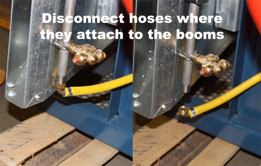
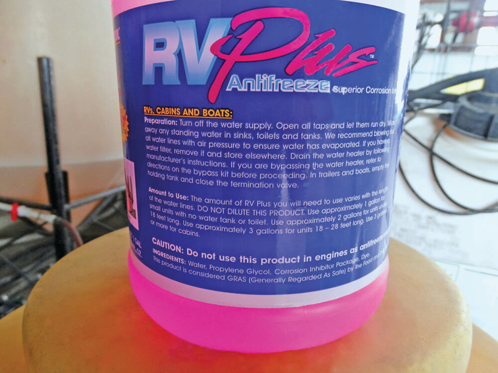
    If you are preparing the sprayer for long-term storage, follow the normal rinsing process, but don’t reinstall strainers and nozzles.

    Look in the nozzle bodies for debris. Discard worn or broken nozzles.
    Soak, scrub, rinse and store nozzles and nozzle strainers. You may replace them once the sprayer is clean, but I prefer to store them separately since they have to come back off during start-up.

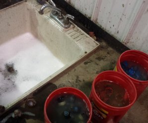
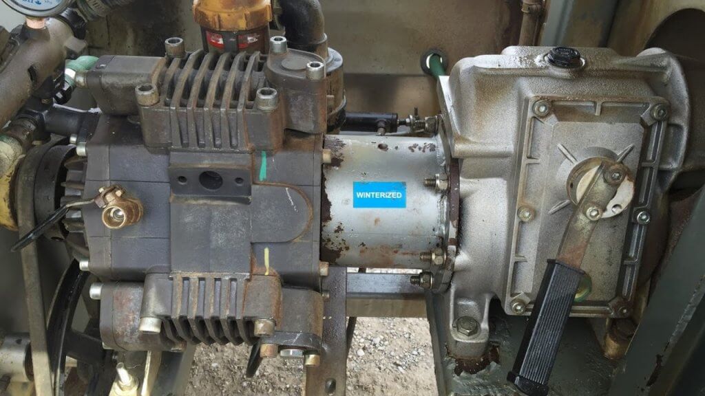
    With the agitation on, circulate undiluted plumbing antifreeze (the sprayer already has 5-10 L (1.25-2.5 gallons) of water in the system from the decontamination process) for five minutes and drain it through the plumbing system (not the booms).
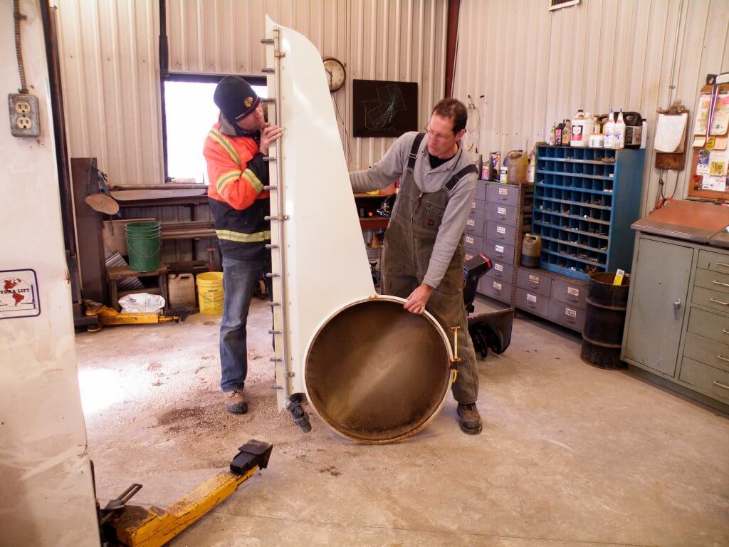
    Disconnect hoses where they attach to the booms and drain as much liquid from the sprayer as possible. (Image from Munckhof Sprayers). Take the time to examine any hose fittings.
    Clean the sprayer (Triple rinse with a detergent) and scrub the exterior. Do not use pressure washers on bearings, fittings, pumps or any lubricated or moving parts.
    Examine fan blades for cracks, build-up or nicks that can cause imbalance. Replace (not just repair) punctured entrance grills.
    Don’t ignore tank damage. Poly tanks are prone to sun damage and cracks. Never climb into a tank to repair it. Quite often, replacement is the best option.
    Clean and inspect wheel assemblies. It’s best to do this during winterization to prevent bearing corrosion as the sprayer sits all winter.
    Remove any rust and repaint (or just touch up). Paint not only looks good, it protects.
    The excellent YouTube channel Ask Tractor Mike proposed storing the PTO shaft indoors in two pieces, and to cut away a portion of the interior guard to facilitate reassembly later on. Also, use a paint pen to mark the splines on the shaft for easier hook-up (see inset top-right of image).
    RV antifreeze is a 50% solution of antifreeze and water with a rust inhibitor. It should not cause phytotoxicity if sprayed or dumped, but be sure to dispose of it away from water sources during start-up. Turn the pump manually to get antifreeze throughout the system. Close the nozzle bodies, loosely fit the tank lid and store indoors. (Image from Purdue Extension publication PPP-121: Preparing Spray Equipment for Winter Storage and Spring Startup).

    Spring Start-up

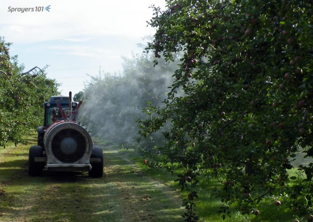
    Most operators are guilty of neglecting their airblast sprayers and babying their tractors. Sprayers are precision tools that must be kept in good operating order to prevent costly breakdowns, improve their performance, and increase their lifespan.

    Your car is serviced based on distance travelled. Your sprayer should receive regular maintenance based on working hours, per the manufacturer’s recommendations. Daily sprayer inspections are part of regular maintenance since the operator will (hopefully) find small problems before they become big problems.

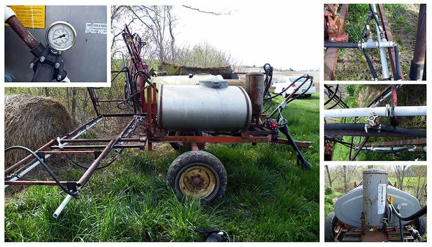
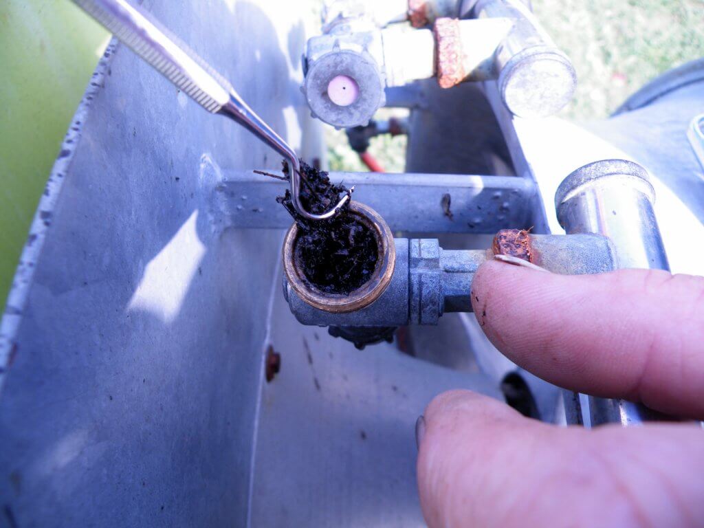
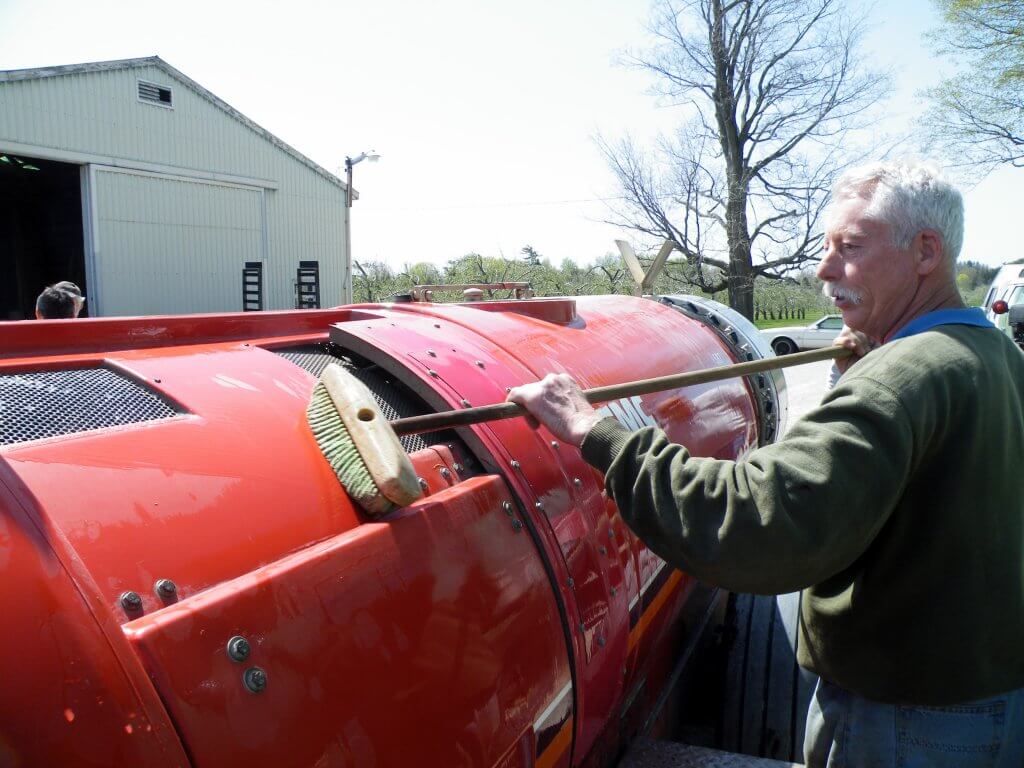
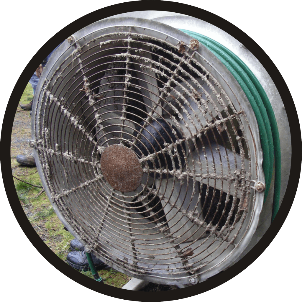
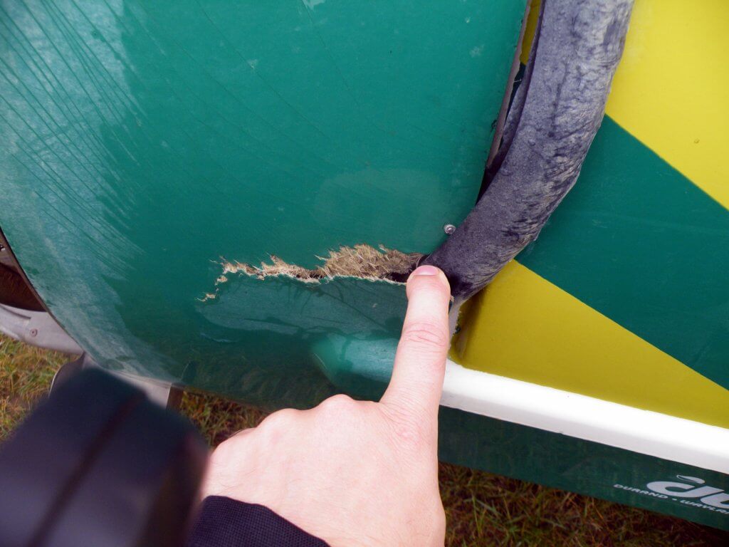
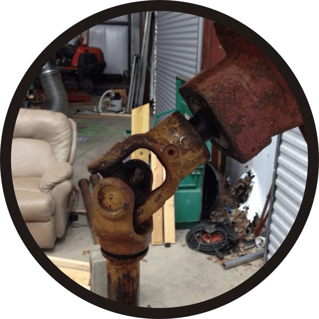
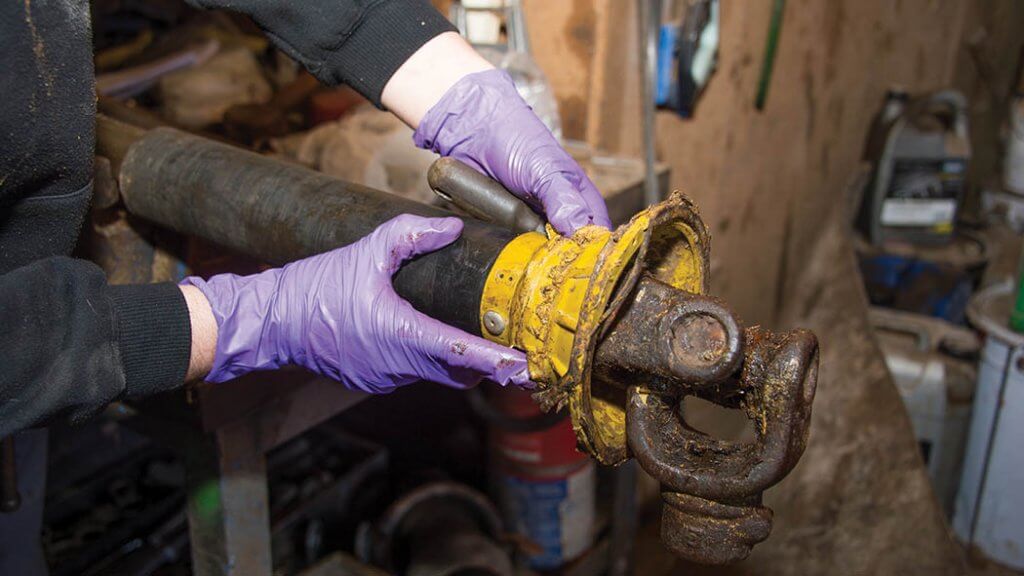
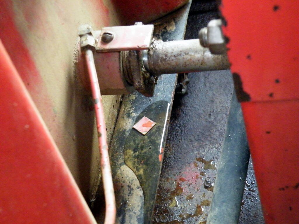
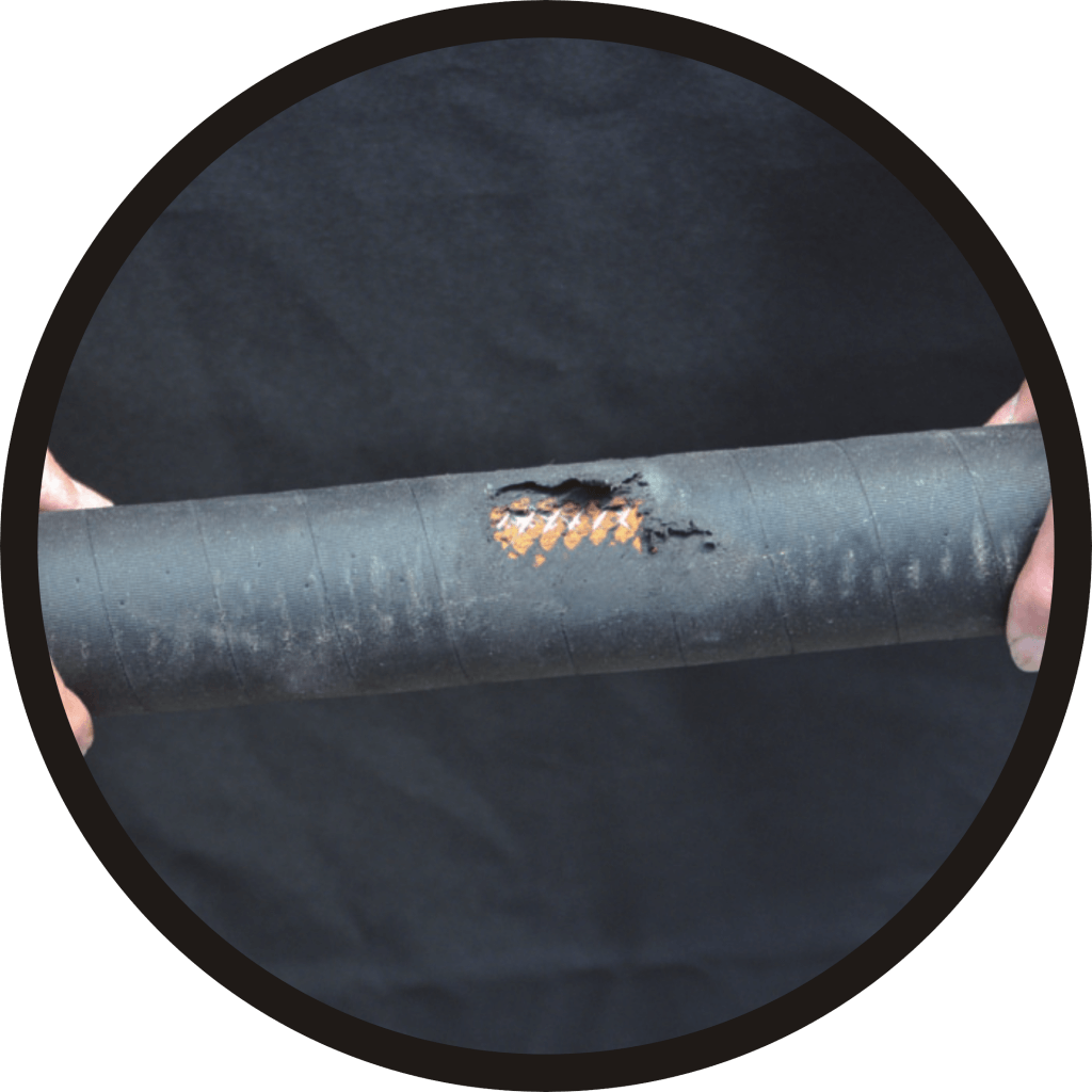
    Never assume your sprayers is ready to go right out of long-term storage. Parts seize, scale breaks away from surfaces, and small beasties sometimes choose to eat, or make their homes in, cozy sprayers.

    When planning spring start-up, never assume the winterized sprayer is ready for immediate hook-up. Expect a minimum half day per sprayer.
    Attempting to loosen or shift something that hasn’t moved in several months is risky. Pressure gauges snap off, fittings crack, welds break. Expect the unexpected and either have spare parts on hand, or a plan to get them quickly.
    Parts are most likely to seize during the first spray. Bearings and PTO universal joints, especially.
    Start-up is a good time to lubricate parts. Grease the guard ring bearing every 100 hours, the universal joint cross every 25 hours and the shaft and shear bolt regularly.
    Insects, birds and rodents eat, or make homes in, sprayers. Professional rodent bait/traps, steel wool and peppermint oil/gel are possible solutions.
    Check belt tension, alignment and wear. (Image from Purdue Extension publication PPP-121: Preparing Spray Equipment for Winter Storage and Spring Startup).

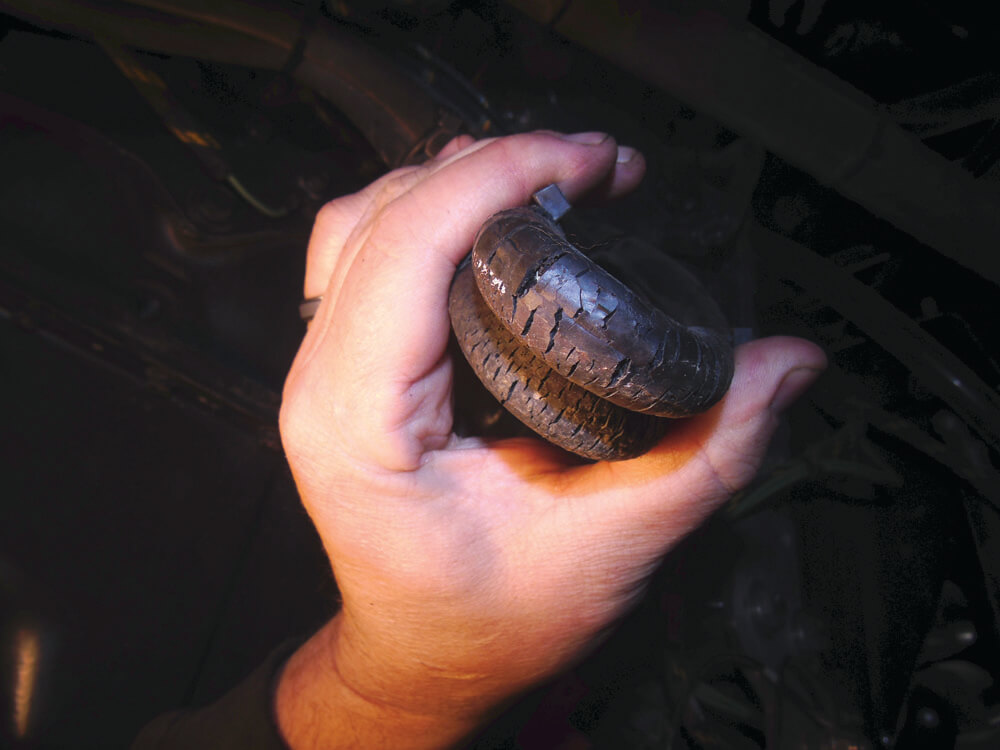
    Pump specific maintenance is beyond the scope of this article. Hypro recommends changing oil after 40 hours of break-in operation and every 500 hours after that. The diaphragms should be replaced every 1,000 hours. Generally speaking, EPDM (black) diaphragms are a better choice for airblast sprayers, while the Desmopan (amber) diaphragms are really for lawn care sprayers.

    Pump maintenance is beyond this article, but change the oil every 500 hr or 3 months. Use a paint pen to write on the pump what type of oil it requires, and then date the filters. Note the “winterized” sticker.

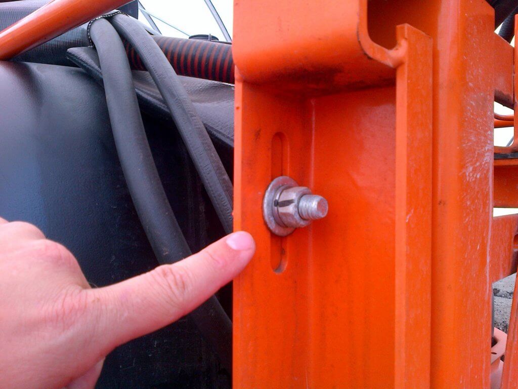
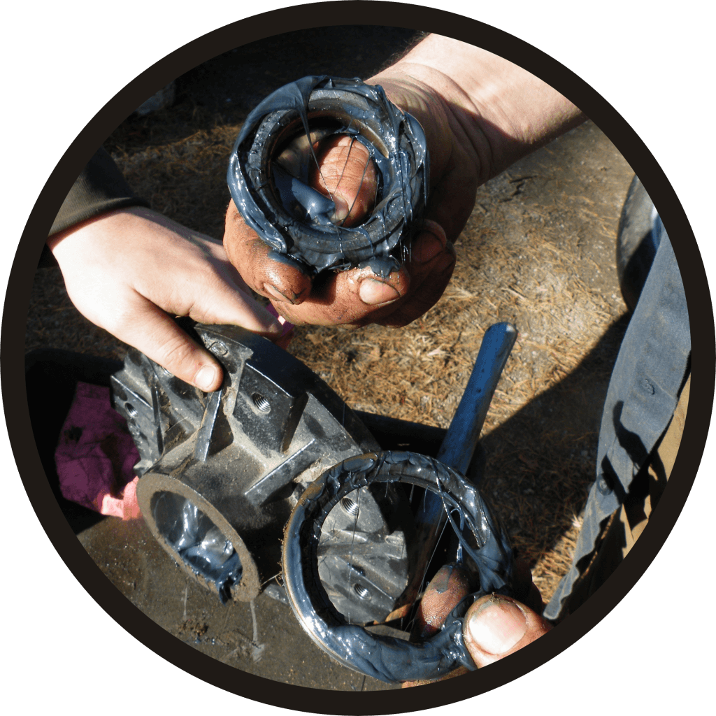
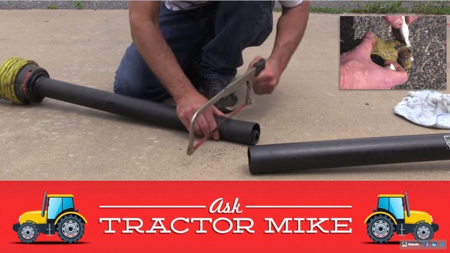
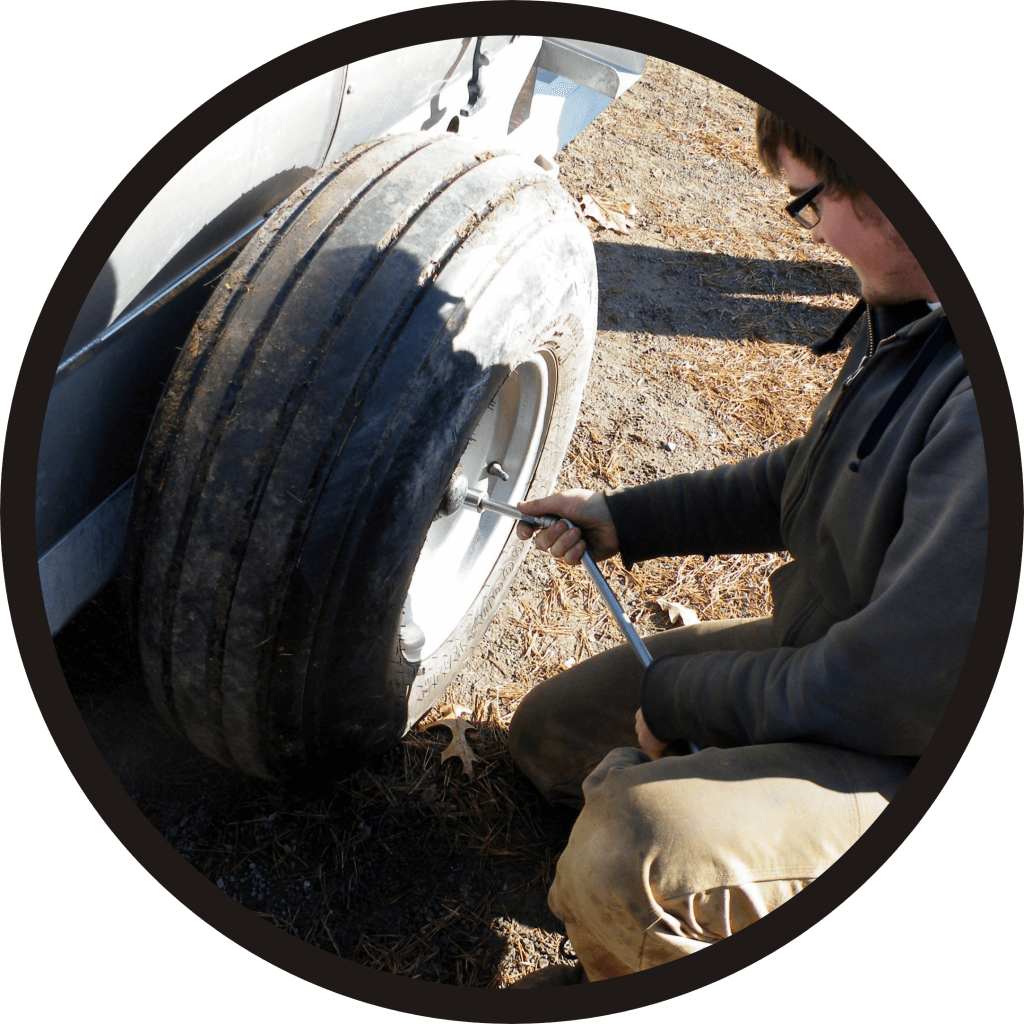
    At minimum, check the tire pressure. Hard tires drive faster, but leave compacted ruts. Soft tires drive slower, but disperse weight better. Airblast sprayer wheel assemblies should be cleaned and inspected as part of regular annual maintenance. Wheel bearing maintenance before long-term storage may prevent water from corroding the bearings.

    Ensure tire pressure matches the ideal stamped on the tire. Or, if using less pressure to avoid spring soil compaction, ensure both tires have the same pressure.

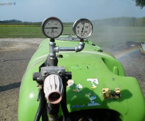
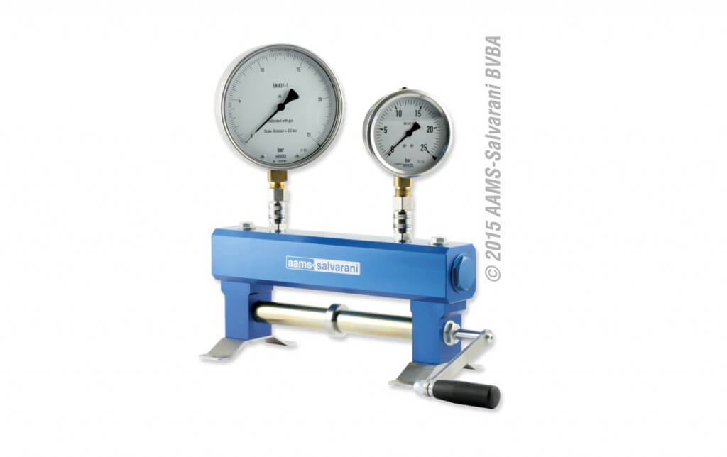
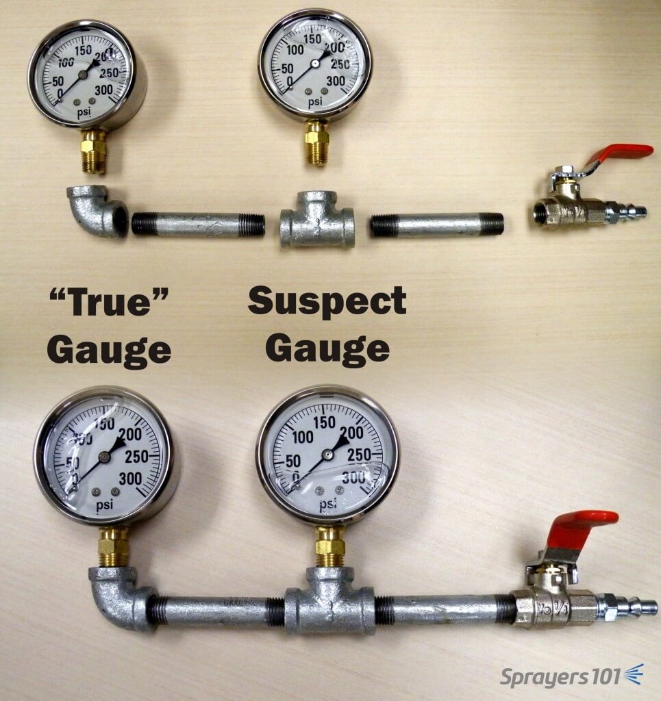
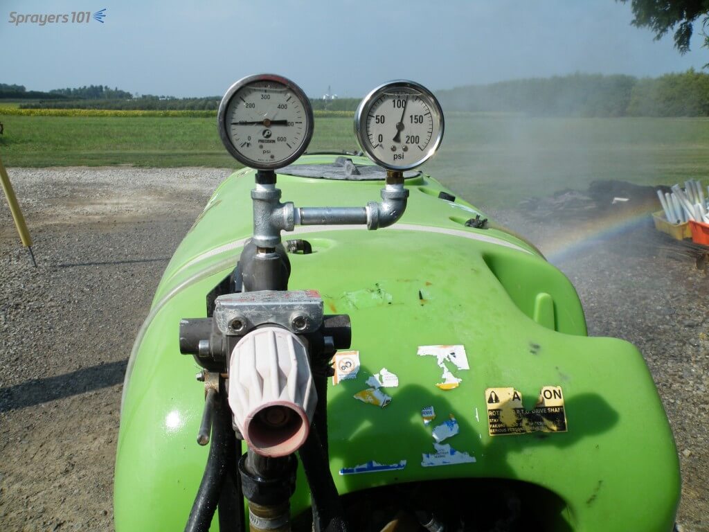
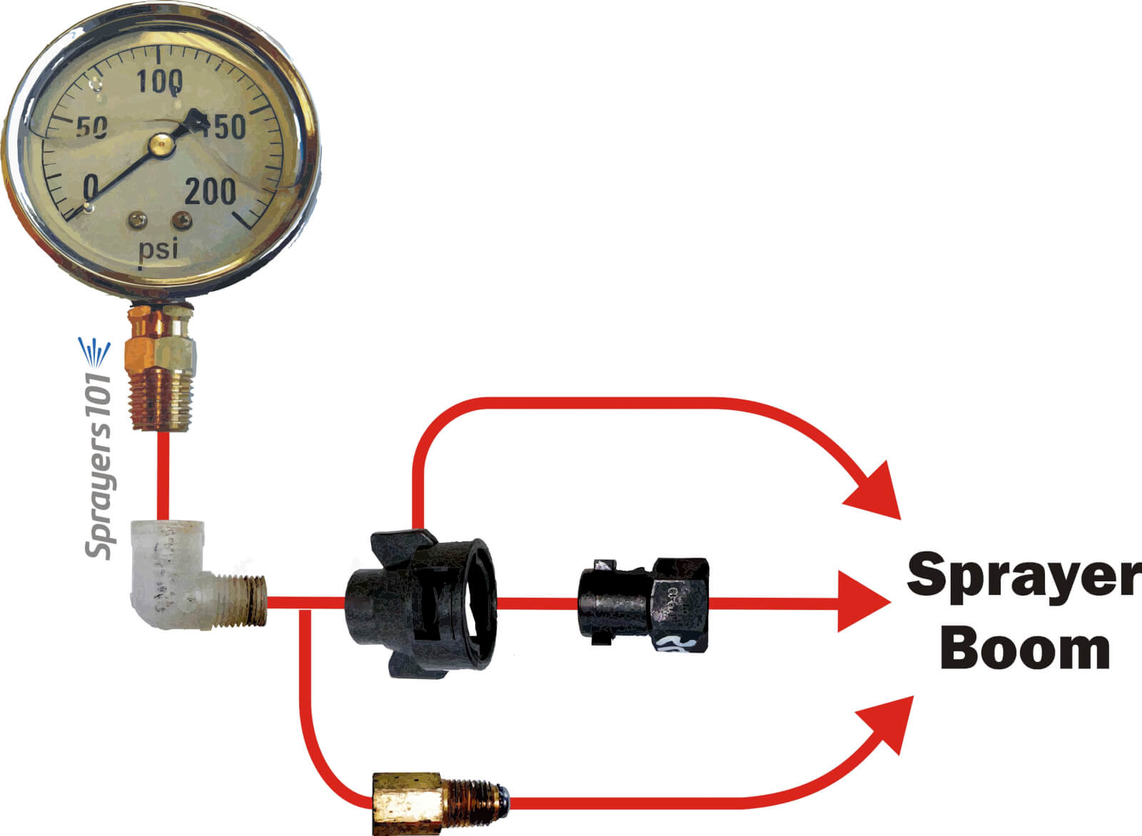
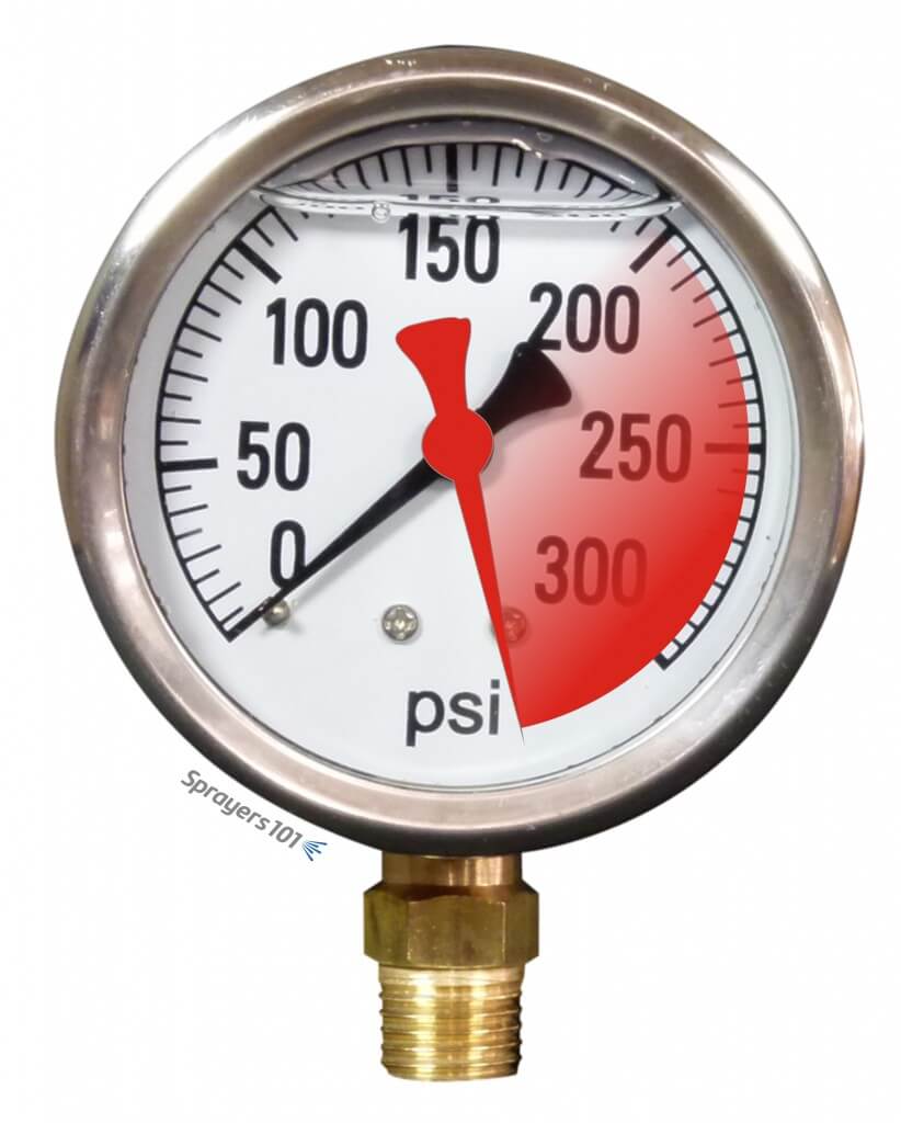
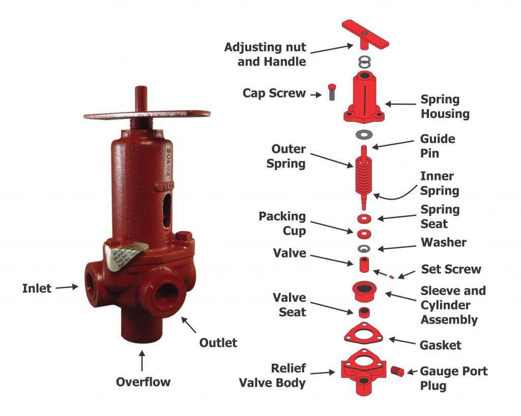
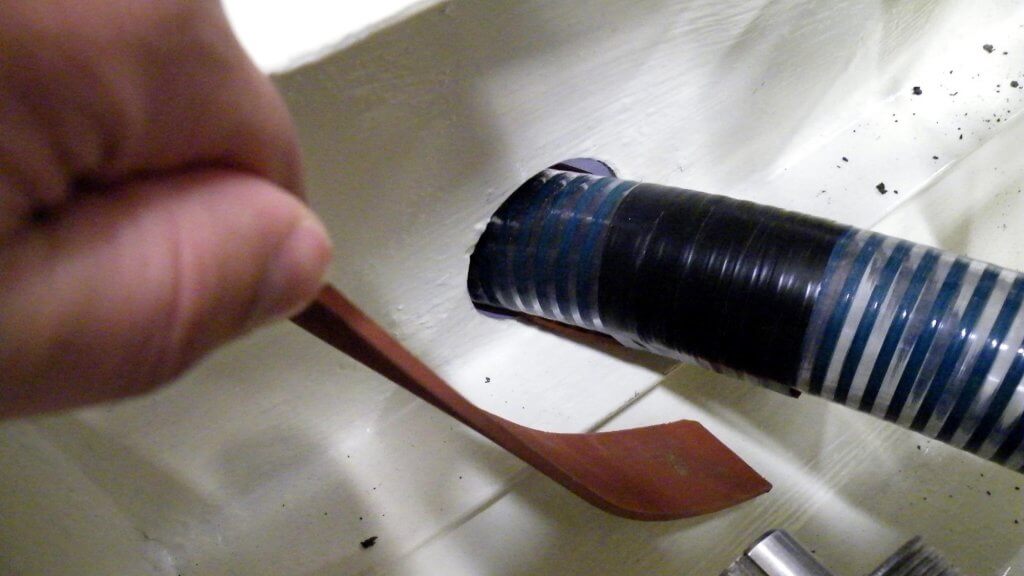
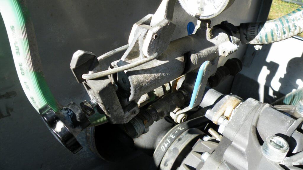
    The relief valve on your sprayer should always be in the bypass position during start-up. If your gauge spikes then the gauge may always read high afterwards and should be replaced.

    A reminder to always set the relief valve to the bypass position when starting up the sprayer. This is one reason why pressure gauges spike and can eventually fail.

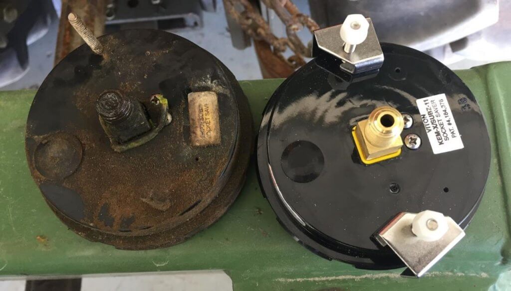
    Replacing leaking, opaque or inaccurate gauges improves sprayer performance. Be sure to use the oil-filled variety of gauge to eliminate a bouncing needle. You can also get suppressors that fit between the gauge and sprayer to prevent pulsing. Consult the article on testing airblast pressure gauge reliability.

    Use a wrench to turn gauges at the nut. Don’t twist them by hand holding the face. Ensure they are not opaque, leaking, plugged or resting above the zero pin.

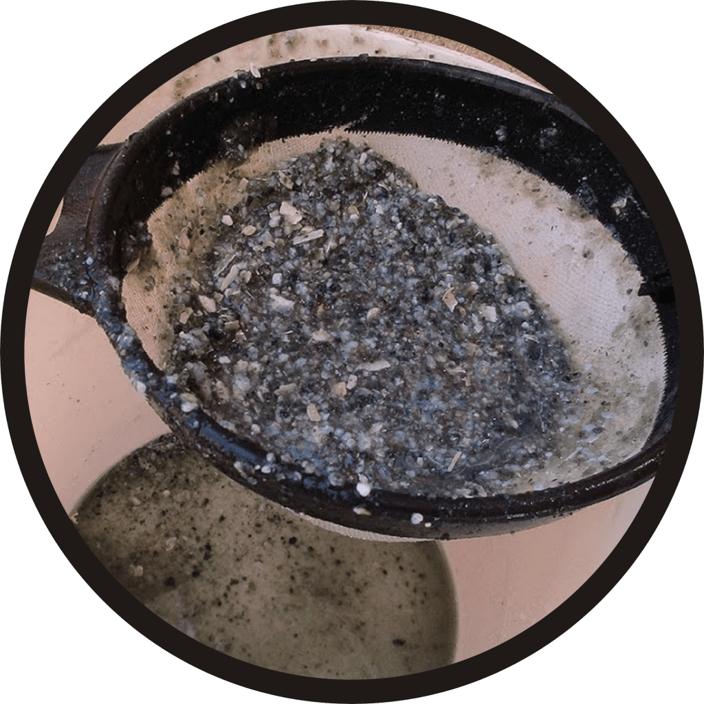
    Many spray materials do not mix well and one of the common causes of uneven application is poor agitation. If you find deposits at the sump in the bottom of the sprayer after an application, your agitation is insufficient. For mechanical agitators, check for propeller wear and ensure paddles are secure on the agitator shaft. Learn more about agitation here.

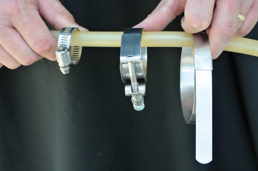
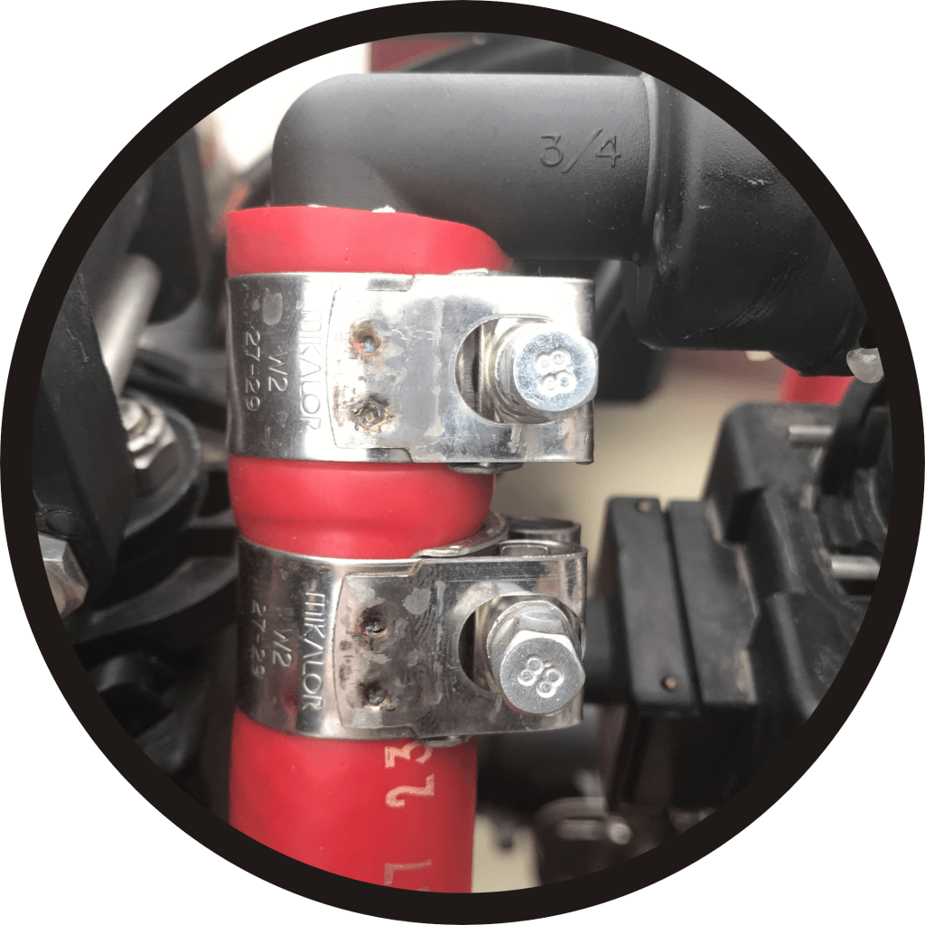
    If the agitator shaft is leaking a little, tighten the packing. The packing gland is a common source of leaks. Keep it properly greased. If a leak occurs you can usually repair it by tightening the bolts on the packing gland by ½ a turn, but if that doesn’t work you may have to remove and repack (or replace) it.

    On sprayers with mechanical agitators, look for prop wear and loose or damaged paddles. Fill the sprayer with water and looks for tank leaks. Tighten the bolts 1/2 turn if the packing gland on the agitator shaft is leaking. You may have to remove and repack the gland if the leak persists.
    Look for signs of hose wear and examine the sprayer for leaks while under pressure. Be careful when pressurizing the sprayer for the first time in the spring; this is when lines are likely to come loose or burst. (Image from Purdue Extension publication PPP-121: Preparing Spray Equipment for Winter Storage and Spring Startup).
    Minerals chelate (i.e. scale) more readily on stainless steel than plastic tanks. In either case, the first tank of water and leftover antifreeze should be sprayed from the nozzle bodies with no line or nozzle strainers, and no nozzles. Replace them once the tank is sprayed out.

    The last step is calibrating the sprayer, and that process really depends on your definition. If the preceding steps conflict with those of the manufacturer’s, always follow the manufacturer’s. Do this for reasons of safety and to preserve any warranty.

    Thanks to Fred Whitford (Purdue University), Gail Amos and Mark Ledebuhr (Application Insight LLC) for reviewing the content of this article and for their helpful edits.

  • Testing and Correcting Airblast Pressure

    Testing and Correcting Airblast Pressure

    The role of pressure is often underappreciated in spraying. Many airblast operators (still) don’t use rate controllers, so the only way to monitor sprayer pressure is using a single liquid-filled pressure gauge located near the pump… and it may not be trustworthy. An inaccurate pressure gauge may cause you to spray more or less product than you intended. That translates to wasted resources and potentially higher residue levels. Conversely, spraying less than intended may lead to reduced efficacy and the need to re-apply. Many operators use budget pressure gauges on their sprayers and have never tested or replaced them.

    Testing pressure gauges

    Here are a few clear indications that your pressure gauge should be retired:

    • Gauge has an opaque or unreadable face
    • Mineral oil leaking or mostly gone
    • Needle does not rest on zero pin when sprayer is not under pressure (it has likely spiked)

    Sometimes a gauge is not obviously in need of replacement. To test it, you need to apply a known pressure to see if it is reading accurately. One way to do this is using a commercial manometer.

    AAMS-SALVARANI Gauge tester
    AAMS-SALVARANI manometer

    These systems work well, but they can be an expensive proposition if you only use them once in a while. In a past sprayer workshop, one participant had a great suggestion for testing gauges. His idea was to use an air compressor (which most farms have) and some simple plumbing to create a homemade manometer. Be sure to vent the gauges before testing.

    The Pressure Gauge Tester. The “true” gauge is in the elbow and can be compared to the suspect gauge in the tee. Concept from K. Voege, Ontario.
    The “Pressure Gauge Tester”. The accurate gauge is in the elbow and is compared to the suspect gauge in the tee. Concept: K. Voege, Ontario.

    This tool allows you to test your suspect gauge (set in the tee) against an accurate gauge (set in the elbow) for less than $75.00 CAD. Construct your own “Pressure Gauge Tester” using the following parts (valve optional):

    PartApprox. Price (CAD)
    ¼” by 3” Galvanized nipples (x 2)$3.50
    ¼” Galvanized 90º elbow$3.50
    ¼” Galvanized Tee$3.50
    ¼” Ball valve (threaded)$10.00
    *Plug Air Connector (A over ¼”)$4.00
    Teflon pipe tape$3.00
    †300 psi liquid-filled gauge$40.00
    *Depending on the quick-connect fitting on your compressor 
    †The range of the accurate gauge should match your existing gauge. The range of your existing gauge should be twice as much as your typical operating pressure. 

    As a public service announcement, be aware that many budget, liquid-filled gauges are inaccurate right off the shelf. A 5% variance is typical. When replacing a worn gauge, or buying the “accurate” test gauge for your homemade manometer, buy a few and save the receipt. Test them in different combinations to ensure they all agree with one another. Return the extras and let the dealer know if you discover an inaccurate gauge. I’m sure they won’t put it back on the shelf for the next person… *ahem*.

    Gauges should be rated twice as high as your average operating pressure. For example, if you typically spray at 150 psi, your should have a gauge rated up to 300 psi. That way, you can see small changes in pressure more clearly. Plus, if your needle is pointing straight up, a quick glance confirms the ideal operating pressure.

    Another way to confirm pressure gauge accuracy is to install a second in-line. They’ll keep one another honest. This may be difficult if the gauge set into a molded plastic tank, or located under the chassis next to the pump where it is not visible from the tractor.

    Two gauges keep each other honest – this GB (Italian-made Good Boy) is sporting a home-made assembly that cost ~$50 to assemble, including the second gauge. The silver spray paint on the black pipe prevents rust and makes it look pretty darn sharp.
    Two gauges keep each other honest – this GB (Italian-made Good Boy) is sporting a home-made assembly that cost ~$75 CAD to assemble. The silver spray paint on the black pipe prevents rust and makes it look pretty darn sharp. Note that they should be the same range, but are not in this photo. The one on the right is the correct range for this operating pressure.

    Measuring and Correcting for Pressure Drop

    Boom pressure can sometimes be less than the desired operating pressure (a phenomenon known as “pressure drop”) and must be accounted for. Pressure drop is affected by hose diameter, hose fittings, and the distance from the pump. You’ll find it at the far ends of boom sections on field sprayers and it’s an issue that plagues many low-pressure, tower-style sprayers. Dress appropriately because you’re going to get wet performing this diagnostic.

    1. Fill a clean sprayer about half-full with water.
    2. Install a liquid-filled test gauge in the highest nozzle position of one of the booms. The image below shows how the nozzle cap or entire nozzle body may need to be removed for this step. For Metric fittings, contact your sprayer dealer – they can be hard to find.
    3. With the tractor parked, bring up the rpms and get the lines to the desired operating pressure.
    4. Open the boom(s) and measure the pressure at the nozzle farthest from the pump. All nozzles on all booms should be open during this test. That’s why you are wearing PPE.
    5. For positive displacement pumps, adjust the main pressure regulator until the test gauge reads the desired pressure. For centrifugal pumps, it is possible to make small changes to the pressure, but more important to note any pressure differential for later considerations regarding nozzle output and spray quality.
    There are many ways to install a gauge onto a nozzle body. Here are three examples of common fittings.
    There are many ways to install a gauge onto a nozzle body. Here are three examples of common fittings.

    Switching between multi and single boom operation

    When sprayers that employ a positive-displacement pump are switched to one-sided operation (E.g., border spraying or during turns), the pressure can change considerably. Most units will experience a pressure increase, thereby increasing the boom output. This is typically an indication of a faulty relief valve, which is positioned between the pump and nozzles. It’s actuated by a spring-loaded piston or diaphragm, opening and closing in response to changes in pressure. The operator sets the desired pressure and any additional pressure forces the valve open, diverting excess flow back to the tank via a bypass.

    Spraying from one boom. This operator checked to make sure the pressure didn’t increase when he closed the second boom. High pressures or sudden spikes could indicate a faulty regulator valve.
    Spraying from one boom. This operator checked to make sure the pressure didn’t increase when he closed the second boom. High pressures or sudden spikes could indicate a faulty relief valve.

    This problem can be greatly reduced by properly sizing the regulator (specifically the spring) to the typical operating pressure. Many sprayers come equipped with regulator springs matched to the maximum pressure range of the pump (often 600 – 900 psi). These springs are unable to respond to changes when operating at lower pressures (E.g., 100-200 psi, which is typical of applications to moderately-sized canopies).

    The springs are so stiff that the liquid pressure is unable to act on the spring and the valve essentially acts as a flow control (throttling) valve rather than a pressure control valve. Liquid pressure is difficult to control using a throttling valve; it is unable to compensate if the tractor engine speed drops while driving uphill and sprayer output is subsequently reduced. Further, this phenomenon can cause pressure gauges to spike.

    Valve springs and seats wear out, such as in this regulator assembly. Check yours each season.
    Valve springs and seats wear out, such as in this regulator assembly. Check yours each season. If you spray using moderate pressures, be sure your regulator spring can compensate for small changes.

    Some sprayer designs attempt to compensate for excess flow during single-boom operation. They employ an additional throttling valve to shunt the volume that would normally would be spraying out through the closed boom. The result is that the pressure should remain constant when a single boom is shut off. If your sprayer has this feature, here’s how you set the valve:

    1. With PTO at application speed and both booms open, adjust regulator to calibrated operating pressure.
    2. Close one boom.
    3. If pressure increases, open throttling valve to achieve calibrated operating pressure. If pressure decreases, close throttling valve to achieve calibrated operating pressure.
    4. Repeat process for the other boom, and find a compromise position for the valve.

    Some operators elect to remove the handle from the throttling valve once it is set so they don’t accidentally bump it later. That’s fine, but further adjustments may be required when transitioning between dilute and concentrated volumes, so don’t lose the handle.

    Here’s an oldie-but-a-goodie filmed in New Hampshire in June, 2014. It’s something to keep in mind when you’re getting your sprayer ready for spring service. Thanks to Chazzbo Media and Penn State Extension for making an unscripted and spur-of-the-moment concept into a polished video.

  • Compulsory, Standardized Sprayer Inspections

    Compulsory, Standardized Sprayer Inspections

    Spring always brings renewed interest in sprayer calibration. This is good, because a well-maintained and calibrated sprayer will protect crops more effectively and efficiently, as well as reduce the potential for off-target drift and point source contamination.

    Presently, there is no nationally-recognized standard for sprayer calibration in either Canada or the United States. As a result there are many methods, some more stringent than others, spanning activities relating to seasonal maintenance through to precise diagnostic measurements. This means an operator can be in compliance with programs such as CanadaGAP (a food safety traceability standard for fruit and vegetables), and yet only perform the most rudimentary adjustments.

    I was first made aware of “compulsory inspections” in 2009 when I started noticing certification stickers on certain European import airblast sprayers. Some Ontario tender fruit and grape growers familiar with the European standards asked why we didn’t enforce standardized calibration program as they do in Europe. I was surprised to hear a farmer ask for more paperwork, so it made me wonder, are Canada and the US overdue for a change?

    All sprayers, from large, commercial field and airblast sprayers, to the more humble home-grown sprayers (see below) benefit from regular servicing and calibration. And yet, sprayer calibration in Canada and the US remains largely voluntary and highly variable depending on the size of the operation, sprayer design and the willingness/skill of the operator.

    Canada and the US: Then

    In the mid 1980’s, University of Nebraska engineers and Successful Farming Magazine published a study showing that un-calibrated spray applications were costing US farmers ~$1,000,000,000 per year. The article was infamously called “The Billion Dollar Blunder”. You can download the original journal article describing the survey here.  It was estimated that fewer than 5% of applications were within 5% of the desired rates. Spray overlaps and poor calibration resulted in over-applications of more than 20%.

    At the time it was eye-opening and received a lot of attention. In 2006 the original study was revisited (see here), and even with advances in precision application, there was a disappointing lack of improvement. Bill Casady, University of Missouri Extension agricultural engineer, estimated that if 20 minutes of calibration can save 5% on 500 acres in an application sprayed at $25/ac ($61.75/ha), then the 20 minutes of effort worked out to $1,875 / hour. Now that’s a solid return on investment!

    Belgium: Then

    Belgium recognized and addressed this issue more than twenty years ago. In 1995, following the lead of the Netherlands and Germany, Belgium’s Ministry of Agriculture mandated that all spraying equipment (save backpacks) be inspected every three years. At the time, other countries such as Sweden, Hungary and Austria had similar, albeit voluntary, programs.

    Belgian farmers received letters asking them to make their sprayers available for testing by a Ministry-appointed institution, in locations no more than 10 kilometers from their operations. The institution’s trained technicians would subject the sprayers to a regimented, standardized inspection. When the equipment met the standard, they would receive a permit in the form of a sticker (see below) attached to the sprayer. The growers paid for this service, based in part on the size of the sprayer.

    In order to introduce the process to the Belgian farmer, a short documentary was produced. If you would rather not watch the preamble explaining why the prudent use of chemistry is critical to agriculture, and get right to the sprayer inspection process, skip ahead to 3:35.

    What follows is a brief outline of that 1995 process, which I’m told is similar to the process currently used in Belgium:

    1. Administrators perform visual checks to assess the general condition of the sprayer (e.g. obvious maintenance, safety and operational issues).
    2. Boom balance (where applicable), hinges, boom ends and boom sturdiness is checked.
    3. Nozzle spacing and orientation of nozzle bodies is inspected.
    4. All points of filtration are inspected.
    5. For boom sprayers, a spray pattern distribution used to be performed, but it wasn’t diagnostic enough. Instead, a pressure gauge / nozzle combo is used in each position to check for pressure fluctuation, and to ensure each tip had a flow rate within 5% of the average and no more than 10% deviation from the manufacturer’s rate.
    6. For airblast sprayers, the overall output of the sprayer is measured to determine nozzle wear using individual collectors clamped onto each position.
    7. For sprayers with rate controllers, calibrated collection bags are attached to a few nozzles and the sprayer drives a 100 metre course while spraying. The actual output is compared to the expected.
    8. Finally, the farmer receives a report outlining issues that need to be remedied before the sprayer is certified.

    SPISE: Today

    Today, collaborating European countries are members of SPISEStandardized Procedure for the Inspection of Sprayers in Europe. Established in 2004 by founding members from Belgium, France, Germany, Italy and the Netherlands, the SPISE Working Group aims to “further the harmonization and mutual acceptance of equipment inspections”. They also work to continually improve the inspection / calibration process.

    Their website hosts a number of sprayer-related resources, but the SPICE Advice handbooks are perhaps most valuable to the sprayer operator. Click either image below to download them as PDF for airblast or field sprayers:

    This more current video by AAMS-Salvarani goes though the inspection and adjustment process for airblast sprayers. While there is no mention of air speed adjustments, many of the steps in this video correspond with the airblast adjustments relating to Crop-Adapted Spraying which has proven very successful in Canada.

    Canada and the US: Tomorrow

    Regular, third-party mediated inspections offer many potential benefits to the average operator. But, in order to realize gains in crop protection and environmental stewardship, perhaps there are two programs required: One to certify the sprayer and the other to certify the sprayer operator.

    1. A sprayer inspection program would focus on sprayer maintenance rather than calibration. Maintenance occurs at regular intervals to ensure spray equipment is operating optimally. Calibration is an ongoing process intended to match the sprayer to the conditions in which it’s operating, and that requires an educated sprayer operator.
    2. Sprayer operator education programs such as Ontario’s Grower Pesticide Safety Course, or Penn State’s Pesticide Applicator Certification Course already exist, but they are not offered in every state or province, and they are often voluntary or perhaps specific to a particular expertise (e.g. not applying to custom applicators or airblast operators).

    They could start as voluntary, pay-for-service pilot programs to see if operators appreciate how much better their sprayers are functioning, and to quantify how much waste is been reduced. They wouldn’t necessarily have to be government-run; Industry or Academia may be better conduits. So, what would be required to develop and implement these two programs?

    • We would need to agree on a robust and generic sprayer inspection protocol. We have several European examples to draw on.
    • We would need to agree on the minimal content for a sprayer operator course. Again, we have many to draw on, with the obvious understanding that the core curriculum would be amended to reflect various state and provincial requirements.
    • We would need a trained, third-party organization to take responsibility for overseeing and implementing the two programs.
    • And, of course, we would need the funds to initiate both programs before they would eventually become self-sustaining.

    So, are we dreaming in Technicolor? If responses to this article are any indication, there are those in western society that lash out at the idea of mandatory requirements. But there are supporters, too. Maybe we can learn from those European countries that have been doing this for more than 20 years.

    Thanks to Jan Langenakens of aams for reviewing this article, and providing the videos.

  • Selecting a Sprayer Pump

    Selecting a Sprayer Pump

    When I had to replace a pump on a small scale sprayer, I had a lot of questions about how they worked, their capacities, hose sizes, mounting solutions and fittings. I turned to the Pentair Hypro Shurflo catalog and found a very helpful guide on pages 2 – 10. This article summarizes the steps recommended in the catalog.

    Select Pump Style

    Sprayer pumps can be divided into two categories: Positive Displacement Pumps and Non-Positive Displacement Pumps.

    Positive Displacement Pumps

    These include Roller, Diaphragm and Piston pumps. They are self-priming and traditionally operate at high pressures. Flow from these pumps is directly proportional to the pump speed, which is why they require a relief valve and bypass line between the pump outlet and the nozzle shut-off valve.

    • Roller pumps : This is the most popular pump with farmers world-wide. The seal and roller materials should be selected based on their compatibilities with the pesticides.
    • Diaphragm pumps : These compact pumps are popular for use with abrasive and corrosive pesticides. Their oil-filled piston chambers protect the pump materials.
    • Piston pumps : Similar to car engines, these pumps are relatively low-flow and high-pressure and suited for use with handguns sprayers. The piston cup materials should be selected based on their compatibilities with the pesticides.

    Non-Positive Displacement Pumps

    These include Turbine (or Transfer) and Centrifugal pumps. They must be primed and traditionally operate at low to medium pressures, although there are models available that can go up to 190 psi. Flow from these durable pumps comes from a rotating impeller that feeds liquid through the lines instead of pumping “per stroke”. Therefore, if the outlet is closed for brief periods, the impeller spins harmlessly, so a relief valve is not needed.

    Determine PTO Pump Drive

    When selecting a pump, you must specify the shaft rotation. Hypro suggests two steps for determining the required rotation:

    1. Eyes on the End: Face the rotating Power Take-Off (PTO) and determine if it is spinning clockwise (CW) or counter-clockwise (CCW).
    2. Opposites Attract: The pump must rotate opposite to the PTO. For example, if the PTO rotates CW, then the pump must rotate CCW and vice versa.

    You should also be aware of your tractors’ horse power, and in order to determine the size of pump shaft, you should know the spline dimensions (e.g. 1-3/8″ (6 spline) pto shaft or 1-3/8″ 21-spline pto shaft).

    Determine Pressure and Flow Requirements

    In order to size the pump, you have to know the sprayer settings, such as intended application rate, average ground speed, agitation requirements, etc. Most can be calculated form the following formulae (provided in US and Metric units):

    Calculating Agitation Requirements

    • Liquids :

    Tank Volume (US gal.) × 0.05 = Agitation Requirement (gpm)
    Tank Volume (L) × 0.05 = Agitation Requirement (L/min.)

    • Wettable Powders and Flowables

    Tank Volume (US gal.) × 0.125 = Agitation Requirement (gpm)
    Tank Volume (L) × 0.125 = Agitation Requirement (L/min.)

    If the sprayer has a hydraulic agitation system equipped with a jet, it multiplies the agitation output without the need for additional flow. For example, it might have a 1 gpm input flow and boost it to a 10 gpm output. This savings should be accounted for:

    Agitation Requirement (gpm) × (Input ÷ Output) = Total Agitation (gpm)
    Agitation Requirement (L/min.) × (Input ÷ Output) = Total Agitation (L/min.)

    Therefore, if you calculate a 60 gpm requirement for agitation, and have a jet that boosts the output 3:1:

    60 gpm x (1 / 3) = 20 (gpm)

    Calculating Nozzle Requirements

    Once the agitation requirements are accounted for, you have to account for nozzles. The calculations are a little different for each sprayer, but they amount to the same thing – Total flow in US Gallons per minute or Litres per minute. Here is the calculation for a boom sprayer. For an airblast sprayer, assuming you are spraying every row, substitute “Row Spacing” for “Boom width”.

    Total Flow Requirement (gpm) = [Output (gpa) x Ground Speed (mph) × Boom width (ft)] ÷ 495

    Total Flow Requirement (L/min.) = [Output (L/ha) x Ground Speed (km/h) × Boom width (m)] ÷ 600

    When the flow requirement for agitation and the flow requirement for the nozzles have been calculated, they are added together. It is important not to under-size the pump, so always factor in an extra 20% to compensate for changes in performance (such as pump wear and slower ground speeds) and restrictions in the plumbing systems that can cause pressure drops between the pump and nozzles, as follows:

    (Agitation Requirement + Nozzle Requirement) × 1.2 = Total Flow Requirement

    Finally, be sure to account for any other flow requirements, such as tank rinsing nozzles and hose length/diameter (which causes pressure drops), and have some idea how you want to place the pump relative to the tractor and sprayer. If you prepare all this information, you can quickly and easily discuss your options with the retailer and select the pump that best suits your needs.

    For more information on various types of pumps, check out this article by Dr. Bob Wolf:

  • Pressure Spikes and Relief Valves on Air-Assist Sprayers

    Pressure Spikes and Relief Valves on Air-Assist Sprayers

    A properly-sized pump should produce more flow than is needed and work in conjunction with the atomizers to regulate that flow. Typical to high pressure pumps, a piston relief valve (aka regulator) should maintain the desired system pressure through the normal speed range of the sprayer, regardless of the number of booms (or boom-sections) that are on or off. This is achieved by balancing the sprayer pressure against the relief valve spring, which must move freely across a range of flows.

    But what does it mean when the pressure gauge briefly spikes off-scale when boom are turned on or off? This is bad for the gauge and will eventually cause it to fail. Quite often, pressure spikes are an indication of one of two things:

    • A dirty or stuck valve
    • An inappropriate spring size
    A pressure gauge spiking beyond its range.
    A pressure gauge spiking beyond its range.

    Relief valve maintenance

    Sometimes, pressure spikes indicate a need for valve cleaning and maintenance.

    • The regulator spring cavity may be packed with dirt, which limits valve travel. Clean the housing and spring, and then lubricate and adjust.
    • The regulator may be partially seized or sticky. If the regulator piston and cylinder bores are caked with spray they will ‘hold’ the valve until the pressure/spring balance overcomes the friction.
    • Sometimes valve, and/or the valve guide pin are seized. Disassemble them, clean all sliding surfaces, then lubricate and adjust.
    • Valve/seat wear may have created a leak. You may have already tightened the spring to compensate, but this loads the spring past the pressure balance point you want to spray at. This means that when the booms are shut off, the pressure increases until it reaches the ‘new’ spring balance point. Repair (or replace) the regulator, then lubricate and adjust. Be aware that any leak (external or internal) can contribute to this condition and tightening the spring isn’t the solution.
    • The spring may be damaged (e.g. bent, corroded, etc.). Replace the spring, lubricate and adjust.

    Note: Be sure to read the operator’s manual before you do anything. You should understand your sprayer’s design before you perform any maintenance, adjustments or calibration.

    Spring size

    Sometimes, the relief valve may be mechanically sound, but the spring may not be sized to match a reduced operating pressure. Relief valve springs match the maximum pressure range of the pump. Sprayers operated at lower pressure may be unable to compress the spring. This is common when people switch from disc-core nozzles operated at higher pressure to molded nozzles operated at lower pressure.

    This would manifest when one boom is shut off for single-boom operation; there may not be enough pressure to open the bypass. As a result, flow increases over the remaining boom.

    Recognizing this problem, some operators have teed-in a second relief valve capable of finer adjustments at lower pressures. Make sure you know what you’re doing if you’re considering this option.

    Technically, a spring can either be too weak, or too heavy:

    • The spring may be too weak for the pressure being used (i.e. any adjustment bottoms out). In order to obtain sufficient pressure the operator tightens the spring until it is virtually collapsed, essentially creating a fixed orifice. When the booms are closed the ‘fixed orifice’ doesn’t compensate and pressure rises to force the increased flow through that small orifice.
    • If the spring is too heavy for the pressure being used (any adjustment barely touches the spring when pump is turned off). In this case, the pressure being used will not deflect the spring, so the operator closes the regulator until the ‘fixed orifice’ creates sufficient restriction to flow to achieve the desired pressure. When the booms are closed the ‘fixed orifice’ doesn’t compensate and pressure rises to force the increased flow through, or until the spring begins to deflect.
    • In either situation the spring must be sized so it is in the centre-third of its flex range (i.e. rest state > fully collapsed) at the desired pressure. You can buy springs from the sprayer dealer or hardware supply. Try to maintain original length and diameter of the coil, while varying the diameter of the wire.

    Engineering

    In some cases, it is not a matter of valve maintenance, or spring size, but poor engineering. Consider the following:

    • The valve supply and return may be too small for the pump flow. Consult hose and fitting catalogs for flow capacities and lengths. Re-size the hoses and fittings appropriately, and then adjust the regulator.
    • There may be kinks or sharp bends in in the supply and return lines. Re-route the hoses and/or fittings to avoid kinks and sharp bends, and then adjust the regulator.
    • The relief valve may be too small for the pump flow. Consult a regulator catalog for flow capacities and replace the regulator with an appropriate size. Calibrate the regulator spring and adjust.
    • Relief valves have a ‘cracking’ pressure (that’s when the valve just starts to open). Well-designed regulators have small pressure changes from ‘cracking’ to full flow. That information is in their catalogs. Poorly designed regulators have large pressure changes between these two ratings and these regulators should be avoided.
    • The pump may be too big for system. This often happens when sprayers are upgraded and pumps are replaced. Consult the catalogs and reduce pump size or speed, or increase the sizes of the hoses, fittings and regulator.
    • There may be a hydraulic agitator jet on the regulator ‘tank’ line. An agitator jet applies considerable back pressure to a system, and when booms are closed the increased flow causes more than a linear increase in pressure.
    • Broadly, the sprayer system as a whole may be poorly engineered. Inspect and draw a flow path of the sprayer system. Examine where everything is going (or not going). Is it possible someone made changes that the manufacturer did not intend? Consult the manufacturer if you are uncertain. Sometimes, it will have to be re-engineered, which may require expert consultation.

    Note: Your pressure gauge can tell you a lot more than your operating pressure – it can indicate a problem with your regulator, pump, lines or overall sprayer engineering. Don’t ignore it – address it.

    Thanks to Murray Thiessen, Consulting Agricultural Mechanic, for his contribution to this article.