Pressure is integral to nozzle performance. Reducing hydraulic pressure reduces nozzle flow rate, increases median droplet size, and typically reduces spray fan angle. Increasing pressure increases nozzle flow rate, reduces median droplet size and typically increases spray fan angle.
You can watch this Exploding Sprayer Myths video to learn how pressure, boom height and nozzle spacing interact. In extreme cases, too low a pressure can collapse the fan angle enough to reduce overlap and compromise coverage, as explained in the video at the end of this article.
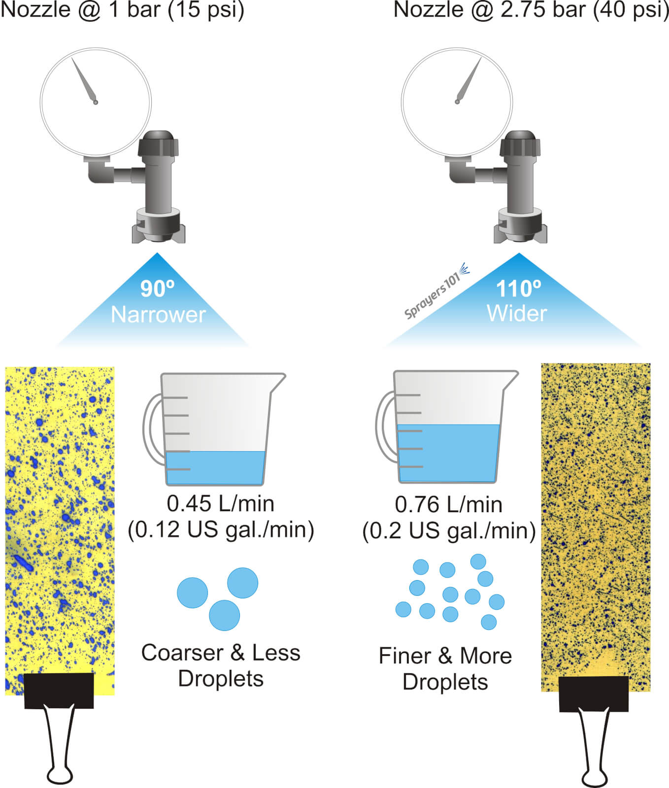
Using a flat fan nozzle as an example, a lower pressure increases the median droplet diameter, reduces the droplet count, reduces the nozzle flow rate and typically reduces the spray angle. Alternately, a higher pressure decreases the median droplet diameter, increases the droplet count, increases the nozzle flow rate and typically increases the spray angle.
Always plan to operate a nozzle in the middle of its recommended range so it can handle small changes in pressure during spraying (such as from a rate controller, or when changing PTO speeds on hilly terrain). Don’t operate an air induction nozzle below 2 bar (30 psi), even if it’s rated lower in the manufacturer’s nozzle table. Most AI nozzles perform best at >4 bar (60 psi).
Pressure can be used on-the-fly to make minor changes to flow rate while spraying. This is how rate-controllers work to compensate for changes in ground speed and maintain a constant overall rate per planted area.
However, pressure should not be used to make significant changes to flow rate. It takes a 4x change in pressure for a 2x change in flow rate, so it’s inefficient. Operating pressures at the upper or lower limit of a nozzle’s range can have undesirable impacts on nozzle wear, median droplet size and swath uniformity.
For a more in-depth discussion of the relationship between spray pressure and nozzle performance, and how rate controllers work, check out this article.
Note: It is far better to simply switch nozzles when a significant change in flow rate is required.
In 2015, we ran demonstrations at Ontario’s Southwest Agriculture Crop Diagnostic Days. The 20 minute sessions were designed to explain:
Although manufacturers of air induction nozzles often rate their performance as low as 15 psi, such a low pressure collapses the spray pattern and the resulting gaps reduce coverage. Additionally, the spray quality at such low pressures is coarser than at higher pressures, reducing the number of droplets available. This further reduces coverage potential.
This video covers the key speaking points from that demonstration.
Low drift nozzles have become the standard way to apply pesticides from a boom sprayer. In order to use them properly, we need to understand how they are designed and how they are intended to work.
Sprayer nozzles have three functions on a sprayer.
Metering flow
Atomizing liquid
Distributing liquid uniformly
Accurate metering of the flow is done through precise machining or molding of the nozzle.
Atomization of a liquid occurs by imposing some sort of force on the liquid that causes it to break up from a stream or a sheet into droplets of the desired spray quality.
Distribution is done by generating a pattern that, in combination with adjacent nozzles, produces similar dosages in appropriate droplet sizes and densities, along the target area.
All three of these functions are confirmed by the nozzle manufacturer, but the properties are likely to change with wear.
Atomization
Atomization forces could be air-shear (used in some aircraft, airblast, or twin-fluid nozzles), centrifugal energy (used in rotary atomizers), electrical energy (used in some electrostatic sprayers), or hydraulic pressure (used in the most common nozzles, the flat fan or hollow-cone tips).
Typically, the higher the applied energy, the greater the break-up of the spray. More air-shear resulting from faster aircraft or fan speeds, faster rotation of a cage, or more hydraulic pressure all have similar effects: they create finer sprays.
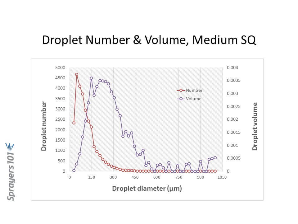
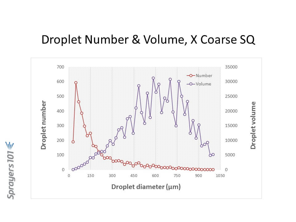
Most nozzles produce polydisperse sprays, comprised of a large number of different droplet sizes. For hydraulic flat fan nozzles, droplets ranging from 5 to 2000 µm can be produced. The exact distribution of the volume in these droplet sizes depends on the nozzle design, the spray liquid, and the pressure. Here are three examples, representing approximately Medium, Coarse, and Extremely Coarse sprays.
Droplet size distribution by number and volume from a Medium spray. Note the majority of the droplets are small, but the majority of the volume (dose) is in somewhat larger droplets.
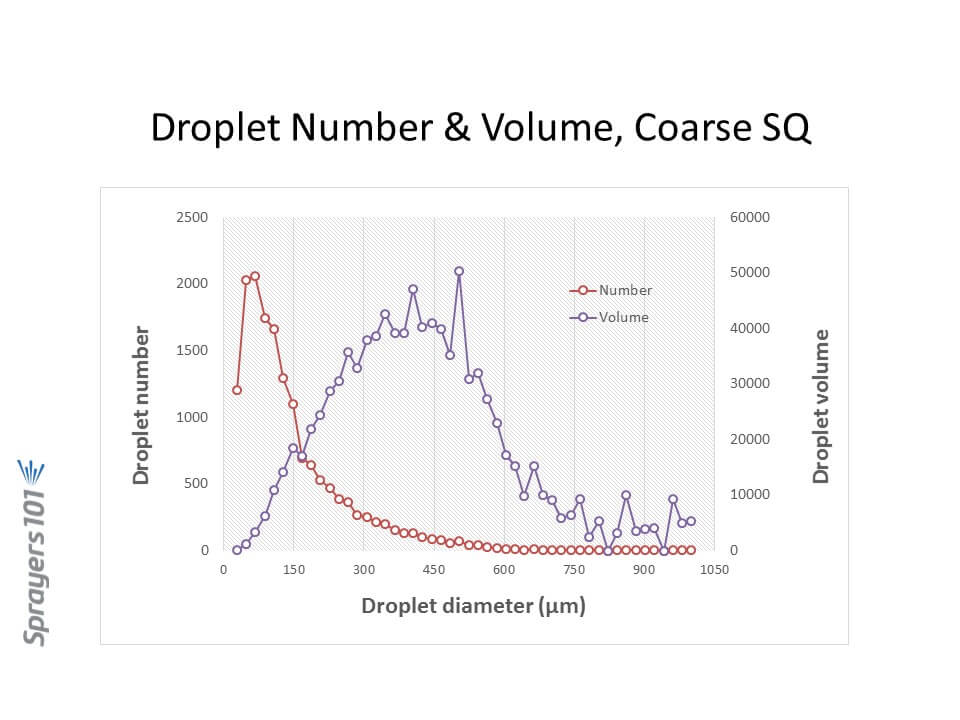
Droplet size distribution by number and volume from a Coarse spray. Like in the Medium spray, the majority of the droplets are small although there is fewer of them. The majority of the volume is in intermediate sized droplets.
Droplet size distribution by number and volume from a Very Coarse spray. While the majority of the droplets are small as in the finer sprays, their overall number is sharply reduced from the finer sprays. The volume is now in the largest droplet sizes.
Let’s focus on hydraulic nozzles, by far the most common in agriculture.
Spray Pressure
Spray pressure is a useful tool for controlling droplet size from any hydraulic nozzle. Need a finer spray? Add pressure. It is also the basis for the age-old recommendation that lower pressures are a good tool for reducing drift.
We impose practical limits on the upper and lower range of recommended pressures based on several other factors, chief among them the spray pattern.
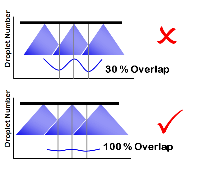
Spray patterns of a certain width, or angle, are required for proper pattern overlap. The convention is to space hydraulic nozzles at 15 or 20 inch intervals along a boom, and operate them at about 20” above the target. Boom height values will depend on the fan angle of the nozzle and the degree of overlap required. For low-drift flat fan tips, a minimum 100% overlap is best. With 100% overlap, the spray pattern width at target height is twice the nozzle spacing. With this approach, at any point under the boom, the target receives droplets from the closest two nozzle patterns.
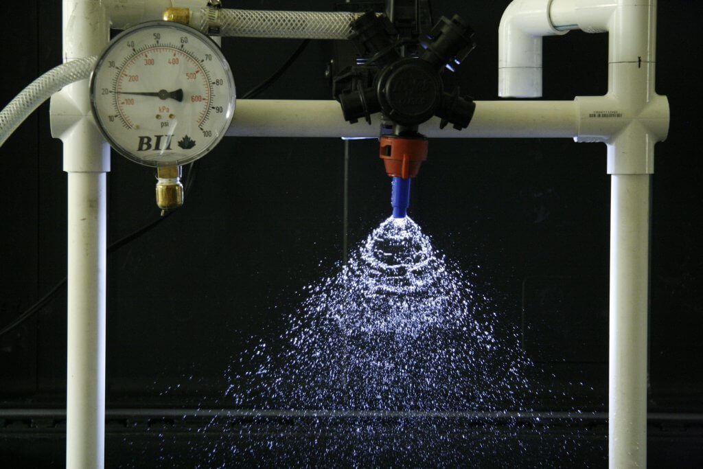
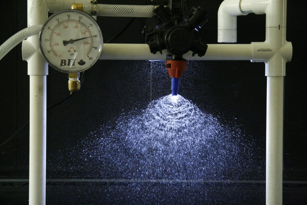
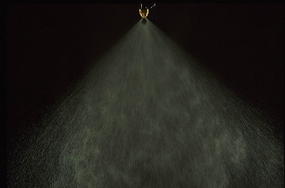
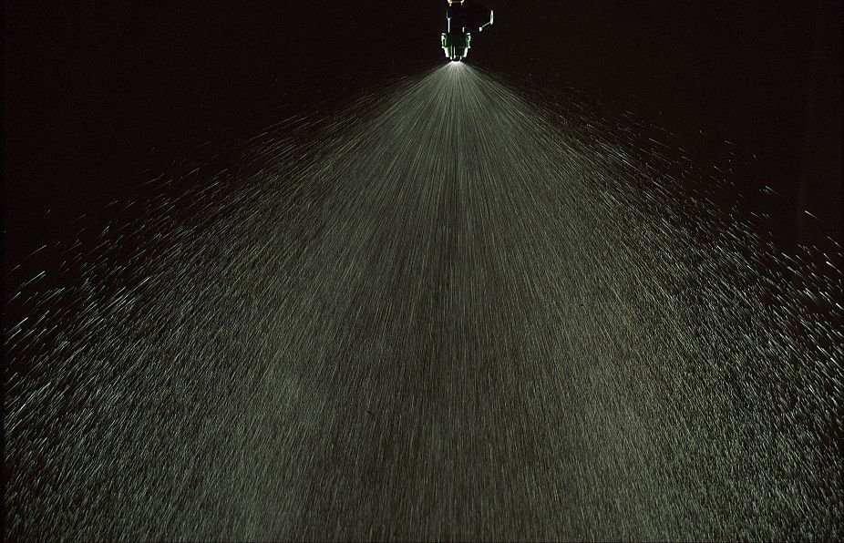
Pattern angles are published by manufacturers, but in practice, angles often differ from those values and can vary with spray formulation. Importantly, they tend to become narrower at lower pressures. The exact pressure at which this happens depends on the tip design, but experience shows that pressures below 20 psi for conventional nozzles, and 30 to 40 psi for low-drift nozzles, result in poor (too narrow) patterns. Narrow patterns reduce overlap, resulting in poor distribution.
TeeJet AI11003 at 20 psiTeeJet AI 11003 at 80 psi
We might also limit pressures at the upper end, based on drift potential. Most conventional flat fan nozzles, for example, drift excessively at pressures above 60 psi or so, hence that limit.
Low Drift Nozzles
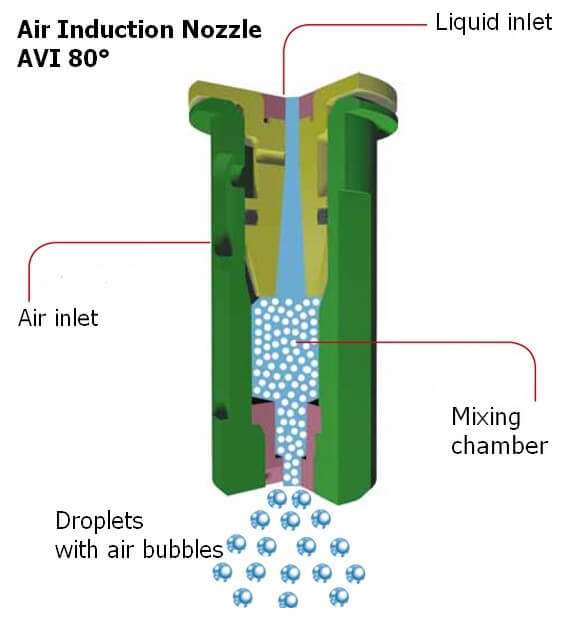
Low drift nozzles were quickly adopted by applicators due to their ability to reduce drift and thereby widen the window of safe spray application. They work by using a two-stage design (often called “pre-orifice”) to reduce the internal operating pressure of the tip. The pre-orifice, the original liquid inlet, is round and sized for the nominal flow of the tip. The exit orifice is eliptical in shape and has a larger flow capacity than the pre-orifice, by about 1.2-fold to 2.5-fold. The larger exit creates an internal pressure drop, so the pattern formation produces larger droplets as though the operating pressure had been reduced. Most modern low-drift tips also introduce air into the nozzle via a built-in venturi. This further suppresses the formation of driftable droplets and introduces air into the interior of the nozzle, adding some pressure back to the system.. The Albuz AVI nozzle schematic below explains the venturi design.
Cross-section of the Albuz AVI venturi nozzle.
The tapered channel inside the nozzle is a venturi, which draws air into the nozzle via integrated ports. When low-drift nozzles are operated beside conventional nozzles at the same pressure, low-drift nozzles produce much fewer driftable fines, and also more larger droplets.
But while the two-stage design is useful for managing drift, it also conceals the actual operating pressure of the exit orifice in these tips. The exit orifice is important – it is the part of the nozzle that does the atomizing and that forms the pattern.
Let’s illustrate the pressure inside a low-drift tip by operating an air-induced low-drift nozzle at 60 psi. This nozzle has a pre-orifice size of 03 (0.3 US gpm at 40 psi, blue) and an exit orifice size of 06 (0.6 US gpm at 40 psi, grey). The operator sees 60 psi on the gauge. What is the exit orifice pressure?
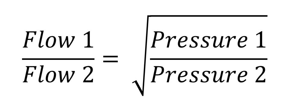
The exit tip has twice the flow-rate of the pre-orifice, and therefore operates at one quarter the pressure, or 15 psi. Recall the square-root relationship between flow rate and pressure.
The relationship between spray pressure and flow rate. Doubling the flow rate requires a quadrupling of pressure
That’s not the whole story. The internal venturi is drawing additional air into the nozzle chamber, and depending on the operating pressure, this could be from 5 to 15 psi. The amount added depends on the specific nozzle, its flow rate, and its pressure. Let’s add 10 psi in this case. The exit tip is actually at 25 psi.
Now let’s assume the pressure gauge reads 40 psi, and that the venturi generates 5 psi additional pressure. The actual exit orifice pressure is now only 15 psi. This is at the lower limit at which a spray is atomized, and at which a good pattern can form.
Our general recommendation with venturi-style low-drift tips has been to avoid pressures below 30 or 40 psi for that reason. We’re trying to prevent the spray becoming too coarse for adequate coverage, and also to prevent the spray pattern from collapsing.
The upside of this design is that the same principle allows for much higher-pressure operation without creating excessive drift. These types of nozzle can, in fact, be operated at 70 to 90 psi without becoming very drift-prone because the pressure at which the spray liquid is atomized is likely only 30 or 40 psi (the actual exit pressure and drift potential will depend on the nozzle and the formulation).
Speed Range
A low-drift nozzle with a pressure operating range from 30 to 90 psi (i.e., 3-fold) would have a flow rate range of 1.73 (i.e., the square root of 3 due to the square root relationship of flow rate and spray pressure). This means that the fastest travel speed (at 90 psi) would be 1.73 times the slowest travel speed (at 30 psi).
A conventional nozzle operating between 20 and 60 psi would have the same travel speed range. So why don’t we just do that? The main reason is that the two-stage design lowers the overall amount of drift substantially, something a conventional nozzle can’t achieve even at very low pressures.
A second reason is that even at high pressures, a two-stage design will likely drift less than an conventional nozzle. This is still the case if the conventional nozzle is operating at low pressures. Any spray quality chart comparing spray qualities of conventional and low-drift tips will demonstrate that.
Pulse Width Modulation
PWM uses a solenoid to intermittently shut off nozzle flow, between 10 and 100 times per second (Hz) depending on the manufacturer. This has implications for nozzle design because the nozzle must not leak liquid during the brief off-cycle. If it does, the small amount of liquid leaving the nozzle will not only not atomize properly, it will also cause a pressure drop within the nozzle which must be replenished with the next on-pulse. This will mean the on-pulse will operate at a lower initial pressure, affecting pattern development and atomization. For this reason, venturi-style low-drift nozzles have not been recommended with PWM. The venturi provides an alternate exit for air or liquid, compromising nozzle performance.
And yet, some venturi style nozzles do, in fact, produce acceptable patterns with PWM according to the nozzle manufacturers. This goes to show that nozzle design can continue to evolve to provide the best in drift reduction technology with PWM. Design for PWM suitability should be at the top of nozzle manufacturers’ agendas.
Nozzle design continues to evolve. But in the foreseeable future, spray pressure will continue to control pattern width and droplet size. That’s why understanding the pressure limits of any specific nozzle type, and maintaining pressure within those limits, is so important in any spray operation.
A very common question we hear at sprayer demonstrations is:
“I want to drive the spray deeper into the canopy – does higher pressure help?”
Well, here’s the classic government answer:
“…yes and no.”
It depends on two things. First, the size of the droplet and second, your tolerance for drift (ours is almost zero, BTW). The following video explains how Fine droplets behave very differently than Coarse droplets. It’s always nice to get outside and toss a few balls around:
Well, that last statement in the video isn’t strictly correct…
It’s true that changes in pressure have greater impact on the momentum of coarser droplets, but there is some impact on finer droplets, too. Sufficiently high pressure makes for a finer spray quality and finer sprays have been shown to penetrate dense canopies more effectively. We have seen improved canopy penetration in ginseng, field peppers and matted-row strawberry using finer spray under higher pressure. If pressure is high enough, it will create air-inclusion and impart additional momentum to even Fine spray droplets over a short distance, but it’s a case of diminishing return. That is, it takes a lot of pressure to do it and relatively speaking they only got a bit faster/further. In our work, we used pressures between 90 and 300 psi. Excepting hollow cones, that’s generally on the upper end, or beyond a nozzles rated pressure range and it may even be outside the pumps capacity.
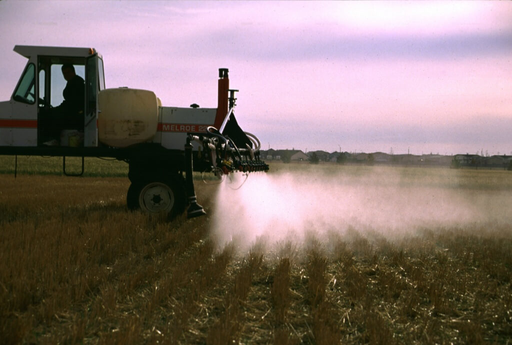
The reason we downplay pressure as a tool for improving canopy penetration is because finer spray under high pressure causes unbelievable drift. A fraction of the spray does get deeper into canopies when you “fog it in”, but the plume of spray blowing beyond the sprayer is entirely unacceptable. Slowing down the travel speed, spraying on cool, humid, low-wind days and lowering boom height can help, but in every trial where we’ve used high pressure and Fine spray quality, we see the image below… or far worse:
Staged drift in peppers using water and high pressure combined with Fine spray quality
The compromise in canopy penetration is to use a Medium spray quality and higher water volume. Stay within the pressure range the nozzle requires to achieve that Medium spray quality. If canopy penetration is still insufficient, consider canopy management (like planting density and pruning) and explore drop-arms to direct the spray, or booms that offer an air-assist or air-deflection option (a few shown here) to entrain and carry spray into the canopy.
Don’t use higher pressure to increase canopy penetration.
Kim Blagborne (formally with Slimline Manufacturing) has long said that the pressure gauge on an airblast sprayer indicates more than just pressure. It can be used to diagnose a number of pump and plumbing issues… if you know what to look for. Here’s Kim’s troubleshooting guide to reading into what your gauge is REALLY telling you:
Scenario One
“As the tank empties, the pressure drops”
First, try adjusting the pressure regulator (assuming a positive displacement pump). If you can maintain the pressure up until the tank empties, your intake line may be loose and it’s sucking the bottom of the tank. Check the fitting between the suction filter and the pump. Apply a light coating of grease to the O-rings on the elbows and filter to ensure a complete seal.
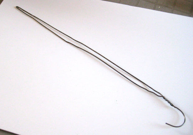
Second, try stopping mid-tank (that is, turn off the tractor PTO and let the sprayer sit for a few minutes). Does the pressure gauge return to the original set pressure? If so, then the intake line inside sprayer has likely come loose entirely. Open the lid, and using a straightened-out coat hanger, hook the intake line and give a few gentle tugs – it should not be able to move. If it does, you’ll have to re-fasten the intake line so it’s not sucking the bottom of the tank.
The humble coat hanger. It opens our cars and now fixes our sprayers. Remarkable!
Scenario Two
“When I first start the sprayer, the pressure drops or fails to maintain constant pressure as the tank empties”
This might indicate improper mixing practices because the filter is probably plugging with product. Alternately, your PTO speed may be too slow to drive sufficient mechanical agitation. Check the suction filter as soon as the problem occurs (don’t finish spraying). If you wait to check when the tank is empty, the evidence of a plugged filter could be washed away before you can confirm it. This problem often happens when spraying nutrients, or when products aren’t compatible.
If that’s not it, it could be a collapsed suction valve. The pump will sound like it’s “missing” (like an misfiring engine). The suction valve might need to be replaced.
Or, perhaps you notice that you can compensate for the pressure drop by adjusting the regulator on the first tank. But it has to be dropped back down again for the second tank. In this case, the regulator might be sticking or jamming. Disassemble it and look for grit in the barrel of the regulator, then lubricate the parts.
Scenario Three
“I lose pressure when I turn my boom(s) on or off”
In this scenario, the pressure is fine as you approach the end of the row. You turn off the outside boom (or both) and finish the turn. But, when you re-engage both booms, the pressure drops. Even when you adjust the pressure regulator to compensate (assuming a positive displacement pump), the unit only gains the lost pressure slowly. In this case, the regulator might be sticking or jamming. Disassemble it and look for grit in the barrel of the regulator, then lubricate the parts.
Scenario Four
“The pressure gauge spikes when I turn off the boom(s)”
If you run a Turbomist, it could be the bypass balance. To solve this issue, head over to this article and pan down to see the step-by-step. If it isn’t the balance, then it’s likely the regulator. The issue of a spiking gauge and how to correct for it is covered thoroughly in this article by Ag mechanic extraordinaire Murray Thiessen.
Scenario Five (a positive displacement pump issue)
“My gauge pulses”
Is it more than a 20 psi range? Have you noticed that the deviation gets less as the PTO speed increases? Well, the pump pressure check-valve may have collapsed. Check the pressure check valves in the pump for broken springs on the suction valve plate.
Does the needle move rapidly through a 5 to 10 psi range? The accumulator pressure might be low. Try adjusting system pressure via the regulator and if that changes how the needle is responding, then set an air compressor to 90 psi (or manufacturer’s recommended pressure) and charge the accumulator.
Perhaps the needle movement is not affected by system pressure changes or the PTO speed. In this case the accumulator may have failed entirely and the diaphragm will need replacement.
Scenario Six
“My calibration is going farther than expected”
Sure, that sounds pretty good at first, but it may be that the gauge is stuck. With the PTO off and the spray boom on, the gauge must read “ZERO”. If it doesn’t, pony up the $50.00 and get a new one.
This article was written by Tom Wolf for “PEI Potato News Magazine”, a publication of the Prince Edward Island Potato Board (http://peipotato.org/). It is reprinted with permission.
PEI Potato News Magazine
“Should I be using low-drift nozzles?” It seems like a simple question with an obvious answer. We all want to reduce spray drift, and this easy-to-use technology is the fastest way to get there.
And yet, the question is more complicated than it first appears. Yes, all applicators want to reduce drift, but many worry about the coarse sprays produced by low-drift nozzles. As a spray volume is divided into coarser (i.e. larger) droplets, there are fewer of them, and that can reduce coverage. It’s a legitimate concern.
Let’s start with our shared value first – the desire to reduce spray drift.
Given the economic, environmental and health impacts of spray drift, the importance is hard to over-state. That’s why spray drift management is a primary concern of our federal regulators whose job is to protect the public interest. It’s also a concern for the neighbours who have a right to keep unwanted products off their property, whether it’s residential or agricultural.
Conventional flat fan nozzles (XR8004) operating at 40 psi
Glyphosate drift with 20 km/h side wind, XR8004 40 psi
Low-drift nozzles (TD11004) operating at 60 psi
Glyphosate drift with 20 km/h side wind, TD11004 60 psi
For these reason, managing drift should be a foremost concern for applicators. The technology is vital to the crop production industry, and if we don’t take care of the issue, someone else will take care of it for us. That’s not the best path.
Of these, the most economical and practical is using coarser sprays via low-drift nozzles. Engineered to emit fewer fine droplets, they are proven to reduce drift by anywhere from 50 to 95% compared to a standard flat fan of the same size. When it comes to reducing drift, they work.
When these tips first hit the mainstream as “pre-orifice” nozzles in the late 1980s, and later as “venturi” nozzles in the mid 1990s, we were impressed with their ability to reduce drift. And the obvious question was, what about product efficacy? Can fewer, larger droplets do the job? The answer, to our initial surprise, was yes.
In the late 1990s, the crop protection industry (including governments, universities, and the private sector), participated in studies throughout Europe, Australasia, and North America looking at low-drift spray performance. In Canada alone, we conducted over 100 studies and concluded that pesticide efficacy was not harmed when a properly adjusted low-drift nozzle was used. A surprising result showed that fungicides did not seem to need finer sprays, contrary to popular opinion, as long as water volumes were sufficient to provide adequate coverage.
As we did more and more studies, it became apparent which points were critical:
When using venturi nozzles, spray pressure had to be increased from the industry standard of 40 psi to about 70 psi. This is because of a venturi nozzle’s two-stage design. The high pressure compensated for an internal pressure drop inside the nozzle. Sprays remained low-drift, but patterns and overall efficacy were better at this higher pressure.
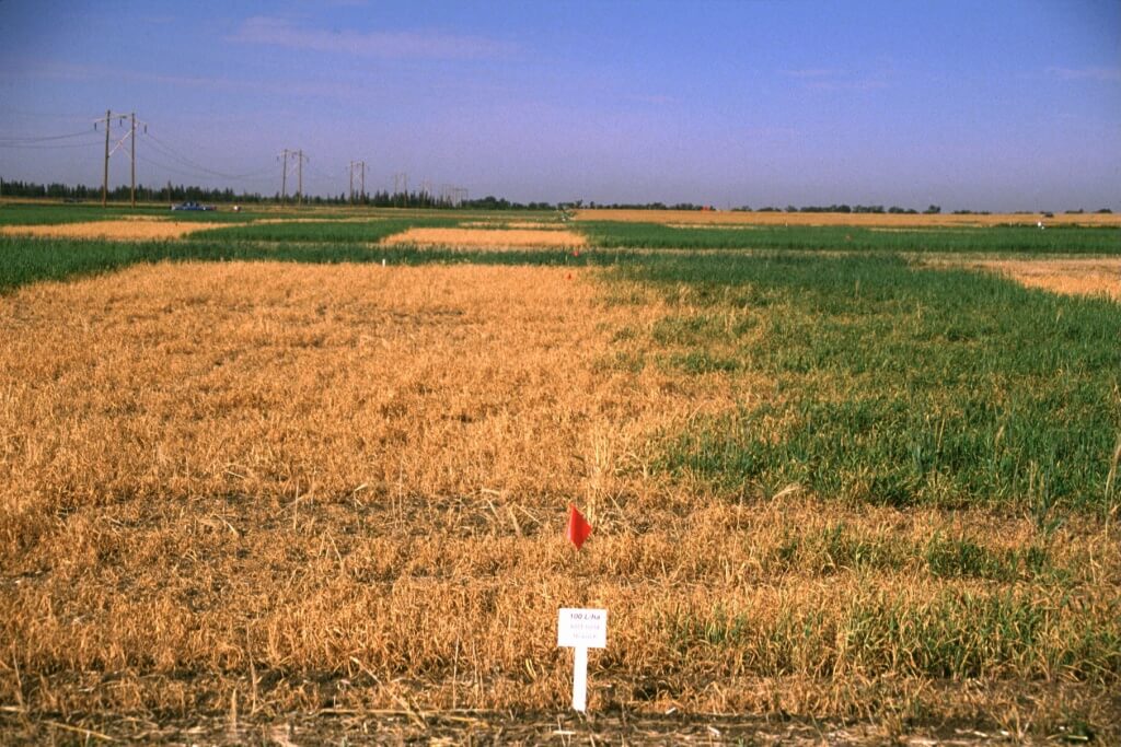
Spray pattern of conventional spray (XR8002, 40 psi)
Spray pattern of low-drift spray (ULD12002, 60 psi)
Spray deposit of conventional spray (XR8002, 40 psi. ~10 gpa)
Spray deposit of low-drift spray (ULD12002, 60 psi, ~10 gpa)
Spray pattern overlap needed to be greater with low-drift sprays – a full 100%. In other words, the edge of one nozzle’s spray pattern should reach the middle of the adjacent nozzles’ patterns. The pattern width at target height was now twice the nozzle spacing and this ensured good distribution of not only the spray volume, but droplet numbers, along the boom.
We needed to pay attention to the target plant architecture and leaf surface properties. Plants such as grasses (with vertical surfaces and difficult-to-wet leaves) often had less spray retention with coarser sprays. Low-drift nozzles worked, but we couldn’t go as coarse in these cases. Careful selection of low-drift nozzles as well as more attention paid to operating pressure solved these issues.
Our minimum water volumes had to increase slightly to compensate for the fewer drops produced by low-drift sprays. This was especially true for contact modes of action where too few droplets-per-area reduced performance. Using an Extremely Coarse spray at a very low water volume was asking for trouble.
Much of my efforts in recent years have been to advise applicators just how coarse they can safely go without harming product performance. This involves things we’ve touched on in this article, like water volumes, modes of action in the tank mix, target plant or canopy architecture, growing conditions, and the like. We’ve arrived at a few rules of thumb, like those above, but as always, it’s dangerous to oversimplify and there are always new situations to grapple with.
While we were learning how to tweak low drift nozzles to get them to perform, we also learned there were significant advantages to using coarser spray qualities.
Foremost, there was an immediate reduction in drift. One applicator told me years ago that switching to a low-drift spray removed a huge burden of worry from him, and that alone was worth it.
Low-drift sprays made it easier to spray on-time, even if weather conditions were marginal for conventional sprays. The result: the timely removal of weeds, or the correct staging of fungicides and insecticides. This has paid large dividends in terms of protected yield.
Coarser sprays can protect product performance from some adverse conditions, such as days with high evaporation rates. On such days, fine sprays evaporate to dryness so quickly that uptake can be limited. Larger drops stay liquid longer, with more uptake the result.
Directed sprays, be they banded sprays or twin fan nozzles for fungicides, make more sense from coarser nozzles. The reason is that these coarser sprays go where they’re pointed, whereas fine sprays lose their path in wind or through travel-induced deflection, very quickly.
We also learned about the air-entrainment that coarser sprays can produce. Large droplets dragged air with them, and smaller droplets could hitch a ride in their wake. This provided a form of air-assistance that reduced drift and carried small droplets into the canopy. Finer sprays had a harder time producing this type of drag, and sustaining it in the canopy.
When we analyzed the droplet size spectrum of coarse and fine sprays, we confirmed that the total number of droplets produced by any given volume of water had been reduced. Not a surprise. But two things struck us.
First, even though the average size of droplets in coarse sprays were very large, they still contained a population of small droplets. In fact, if you counted every single droplet in the spray, the vast majority were small and they were still taking care of coverage.
Second, the critical amount of coverage (measured as the percent of the surface area covered by spray deposits) that was necessary for a given product to work was lower than what we’d been aiming for. In other words, we didn’t need as much coverage as we thought we did, and any excess didn’t actually add to product performance in most cases.
We later analyzed the relationship between spray coverage and herbicide performance and found that the uniformity of the deposits was actually more important than the amount of coverage per se. So, if we focussed on proper overlap and spray pressure there was greater benefit than increased coverage alone. Deposit uniformity has become our research focus of late.
So, should you be using low-drift nozzles? By adopting the changes in pressure, overlap, and water volume outlined above, and paying more attention to the plant architecture and pesticide mode of action, we’ve been very successful in implementing low-drift sprays in all field crops. In my view, we can safely retire Fine sprays for all field crop pesticides. This means conventional flat fan nozzles, hollow cone nozzles, and the like. Get rid of them. All they do is add drift potential.
It’s safe to adopt low-drift sprays. Research and experience from the field prove that they work. Low-drift sprays should be viewed as an agronomic tool that improves application timing and accuracy. And with less drift, we show that agricultural practice can be both efficient and environmentally responsible. That’s going to be a very important story to tell, now and in the future.