- Low-drift nozzles use a two-stage pre-orifice and venturi to lower exit pressure, draw air, and produce larger droplets that reduce drift.
- Spray pressure controls atomization and pattern width. Low pressure narrows patterns, reducing coverage. Venturi low-drift tips generally need 30 to 40 psi.
- Venturi nozzles can leak during off cycle, causing pressure fluctuations and poor patterns, so PWM compatibility varies by design.
This text was generated by OpenAI GPT 5 Mini
Low drift nozzles have become the standard way to apply pesticides from a boom sprayer. In order to use them properly, we need to understand how they are designed and how they are intended to work.
Sprayer nozzles have three functions on a sprayer.
- Metering flow
- Atomizing liquid
- Distributing liquid uniformly
Accurate metering of the flow is done through precise machining or molding of the nozzle.
Atomization of a liquid occurs by imposing some sort of force on the liquid that causes it to break up from a stream or a sheet into droplets of the desired spray quality.
Distribution is done by generating a pattern that, in combination with adjacent nozzles, produces similar dosages in appropriate droplet sizes and densities, along the target area.
All three of these functions are confirmed by the nozzle manufacturer, but the properties are likely to change with wear.
Atomization
Atomization forces could be air-shear (used in some aircraft, airblast, or twin-fluid nozzles), centrifugal energy (used in rotary atomizers), electrical energy (used in some electrostatic sprayers), or hydraulic pressure (used in the most common nozzles, the flat fan or hollow-cone tips).
Typically, the higher the applied energy, the greater the break-up of the spray. More air-shear resulting from faster aircraft or fan speeds, faster rotation of a cage, or more hydraulic pressure all have similar effects: they create finer sprays.
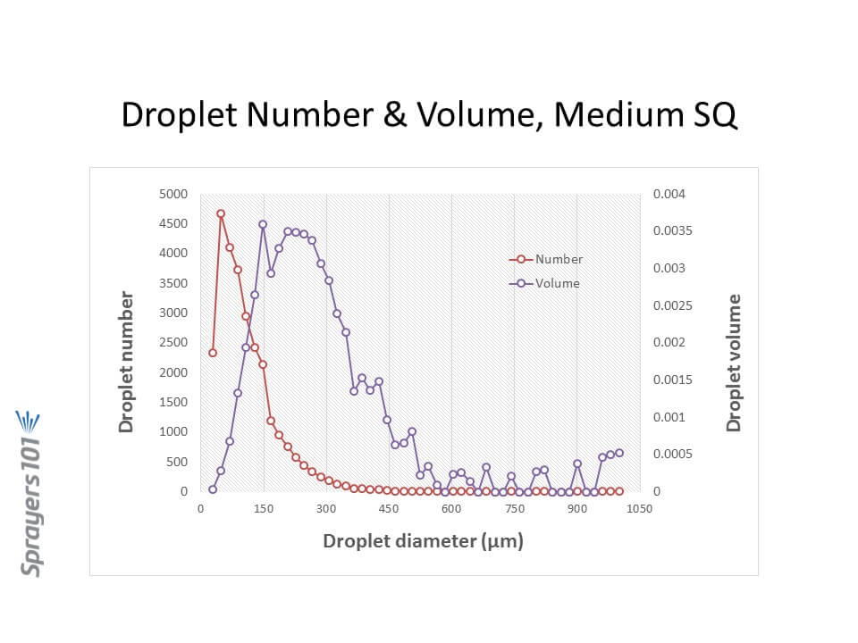
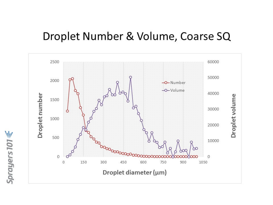
Most nozzles produce polydisperse sprays, comprised of a large number of different droplet sizes. For hydraulic flat fan nozzles, droplets ranging from 5 to 2000 µm can be produced. The exact distribution of the volume in these droplet sizes depends on the nozzle design, the spray liquid, and the pressure. Here are three examples, representing approximately Medium, Coarse, and Extremely Coarse sprays.
Let’s focus on hydraulic nozzles, by far the most common in agriculture.
Spray Pressure
Spray pressure is a useful tool for controlling droplet size from any hydraulic nozzle. Need a finer spray? Add pressure. It is also the basis for the age-old recommendation that lower pressures are a good tool for reducing drift.
We impose practical limits on the upper and lower range of recommended pressures based on several other factors, chief among them the spray pattern.
Spray patterns of a certain width, or angle, are required for proper pattern overlap. The convention is to space hydraulic nozzles at 15 or 20 inch intervals along a boom, and operate them at about 20” above the target. Boom height values will depend on the fan angle of the nozzle and the degree of overlap required. For low-drift flat fan tips, a minimum 100% overlap is best. With 100% overlap, the spray pattern width at target height is twice the nozzle spacing. With this approach, at any point under the boom, the target receives droplets from the closest two nozzle patterns.
Pattern angles are published by manufacturers, but in practice, angles often differ from those values and can vary with spray formulation. Importantly, they tend to become narrower at lower pressures. The exact pressure at which this happens depends on the tip design, but experience shows that pressures below 20 psi for conventional nozzles, and 30 to 40 psi for low-drift nozzles, result in poor (too narrow) patterns. Narrow patterns reduce overlap, resulting in poor distribution.
We might also limit pressures at the upper end, based on drift potential. Most conventional flat fan nozzles, for example, drift excessively at pressures above 60 psi or so, hence that limit.
Low Drift Nozzles
Low drift nozzles were quickly adopted by applicators due to their ability to reduce drift and thereby widen the window of safe spray application. They work by using a two-stage design (often called “pre-orifice”) to reduce the internal operating pressure of the tip. The pre-orifice, the original liquid inlet, is round and sized for the nominal flow of the tip. The exit orifice is eliptical in shape and has a larger flow capacity than the pre-orifice, by about 1.2-fold to 2.5-fold. The larger exit creates an internal pressure drop, so the pattern formation produces larger droplets as though the operating pressure had been reduced. Most modern low-drift tips also introduce air into the nozzle via a built-in venturi. This further suppresses the formation of driftable droplets and introduces air into the interior of the nozzle, adding some pressure back to the system.. The Albuz AVI nozzle schematic below explains the venturi design.
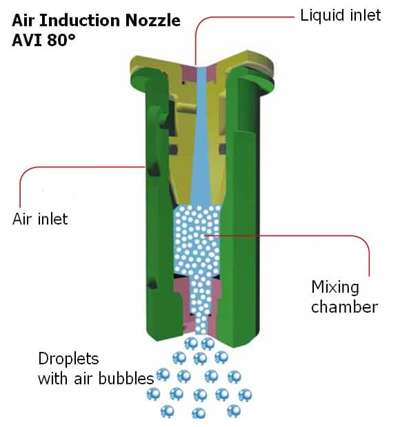
The tapered channel inside the nozzle is a venturi, which draws air into the nozzle via integrated ports. When low-drift nozzles are operated beside conventional nozzles at the same pressure, low-drift nozzles produce much fewer driftable fines, and also more larger droplets.
But while the two-stage design is useful for managing drift, it also conceals the actual operating pressure of the exit orifice in these tips. The exit orifice is important – it is the part of the nozzle that does the atomizing and that forms the pattern.
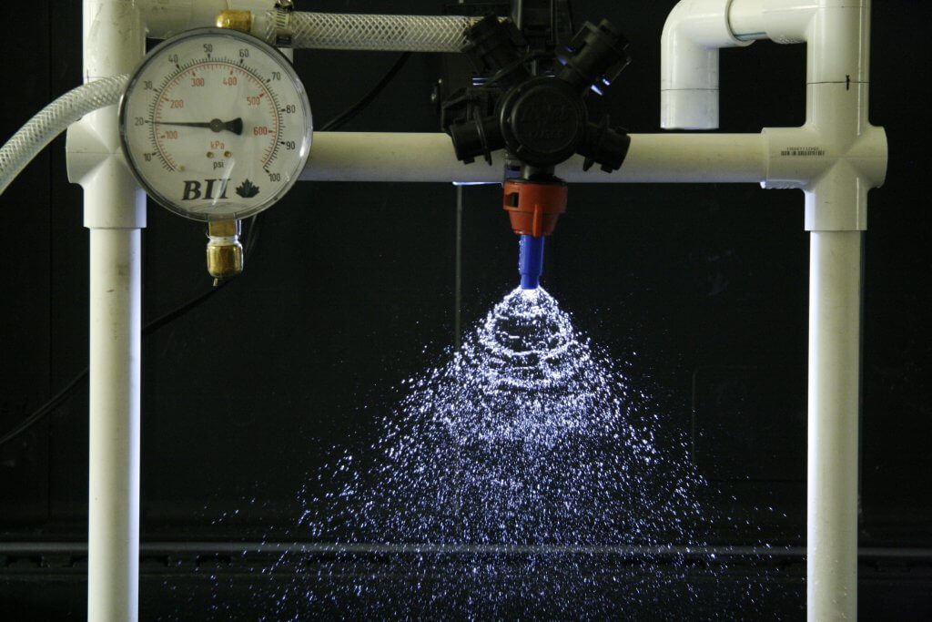
Let’s illustrate the pressure inside a low-drift tip by operating an air-induced low-drift nozzle at 60 psi. This nozzle has a pre-orifice size of 03 (0.3 US gpm at 40 psi, blue) and an exit orifice size of 06 (0.6 US gpm at 40 psi, grey). The operator sees 60 psi on the gauge. What is the exit orifice pressure?
The exit tip has twice the flow-rate of the pre-orifice, and therefore operates at one quarter the pressure, or 15 psi. Recall the square-root relationship between flow rate and pressure.
That’s not the whole story. The internal venturi is drawing additional air into the nozzle chamber, and depending on the operating pressure, this could be from 5 to 15 psi. The amount added depends on the specific nozzle, its flow rate, and its pressure. Let’s add 10 psi in this case. The exit tip is actually at 25 psi.
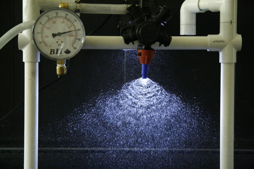
Now let’s assume the pressure gauge reads 40 psi, and that the venturi generates 5 psi additional pressure. The actual exit orifice pressure is now only 15 psi. This is at the lower limit at which a spray is atomized, and at which a good pattern can form.
Our general recommendation with venturi-style low-drift tips has been to avoid pressures below 30 or 40 psi for that reason. We’re trying to prevent the spray becoming too coarse for adequate coverage, and also to prevent the spray pattern from collapsing.
The upside of this design is that the same principle allows for much higher-pressure operation without creating excessive drift. These types of nozzle can, in fact, be operated at 70 to 90 psi without becoming very drift-prone because the pressure at which the spray liquid is atomized is likely only 30 or 40 psi (the actual exit pressure and drift potential will depend on the nozzle and the formulation).
Speed Range
A low-drift nozzle with a pressure operating range from 30 to 90 psi (i.e., 3-fold) would have a flow rate range of 1.73 (i.e., the square root of 3 due to the square root relationship of flow rate and spray pressure). This means that the fastest travel speed (at 90 psi) would be 1.73 times the slowest travel speed (at 30 psi).
A conventional nozzle operating between 20 and 60 psi would have the same travel speed range. So why don’t we just do that? The main reason is that the two-stage design lowers the overall amount of drift substantially, something a conventional nozzle can’t achieve even at very low pressures.
A second reason is that even at high pressures, a two-stage design will likely drift less than an conventional nozzle. This is still the case if the conventional nozzle is operating at low pressures. Any spray quality chart comparing spray qualities of conventional and low-drift tips will demonstrate that.
Pulse Width Modulation
PWM uses a solenoid to intermittently shut off nozzle flow, between 10 and 100 times per second (Hz) depending on the manufacturer. This has implications for nozzle design because the nozzle must not leak liquid during the brief off-cycle. If it does, the small amount of liquid leaving the nozzle will not only not atomize properly, it will also cause a pressure drop within the nozzle which must be replenished with the next on-pulse. This will mean the on-pulse will operate at a lower initial pressure, affecting pattern development and atomization. For this reason, venturi-style low-drift nozzles have not been recommended with PWM. The venturi provides an alternate exit for air or liquid, compromising nozzle performance.
And yet, some venturi style nozzles do, in fact, produce acceptable patterns with PWM according to the nozzle manufacturers. This goes to show that nozzle design can continue to evolve to provide the best in drift reduction technology with PWM. Design for PWM suitability should be at the top of nozzle manufacturers’ agendas.
Nozzle design continues to evolve. But in the foreseeable future, spray pressure will continue to control pattern width and droplet size. That’s why understanding the pressure limits of any specific nozzle type, and maintaining pressure within those limits, is so important in any spray operation.