Celebrating 10 years of “thinking we’re funny”, Exploding Sprayer Myths is back with a new opening sequence!
Join cheesy game show host Wink Boomwobbly and his unsuspecting contestant Joe Mama as they discuss the factors that influence spray droplet fate. How do wind, travel speed, boom height and droplet size affect your pesticide application? Knowing how droplets respond to these forces makes the difference between coverage and drift. Brush up on your fundamentals in a fun way.
Long-suffering RealAgriculture editor Dr. Jay Strove has also hidden an Easter Egg photo so you can play along! Bonus points if you know where it was taken and who it is.
Thanks to our special guest from the UK, and be sure to stick around for the bloopers.
Some pesticide labels require or prohibit certain droplet sizes to reduce the potential for drift. But, even when labels are silent about size restrictions, operators should be aware of the potential for droplet size to affect coverage. In the case of airblast, droplets should be:
large enough to survive evaporation between nozzle and target.
small enough to adhere without drifting off course.
plentiful enough to provide uniform coverage without compromising productivity (e.g. affecting refills and travel speed).
Once spray leaves the nozzle, the operator has no more control over the application, so it’s important to plan for as many contributing factors as possible. Deciding which nozzles to use (and yes, you have alternatives beyond disc-core), requires an understanding spray quality symbols and basic droplet behaviour.
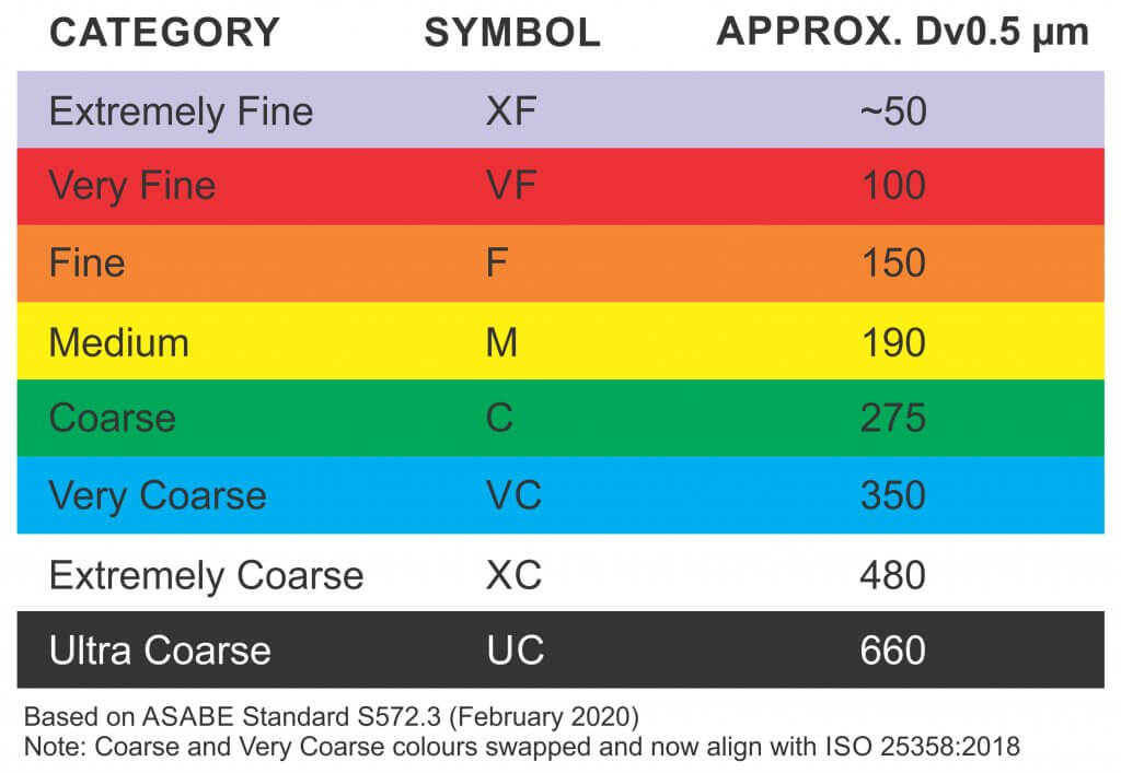
Spray Quality
Droplet diameter is measured in microns (µm). For a given pressure, a nozzle creates a range of droplet sizes which are described by the American Society of Agricultural and Biological Engineers (ASABE) standard S572.3 (Feb. 2020) In North America, these spray quality ratings range from “Extremely Fine – XF” to “Ultra Coarse – UC”. For interest, the scale is based on the British Crop Protection Council (BCPC) system, which is slightly different.
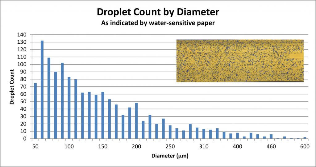
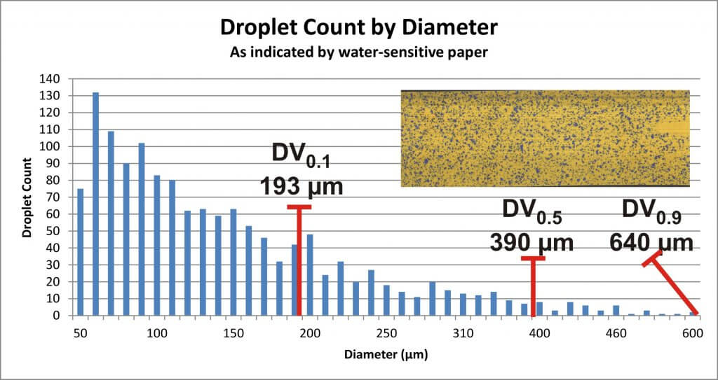
To make sense of the spray quality rating, we must first understand that not every droplet produced by a hydraulic nozzle is the same size. We noted that a single nozzle produces a range of droplet sizes. Spray quality captures that span using a few key metrics. The first is the Volume Median Diameter (VMD) or DV0.5. Think of it this way: Let’s say you have a hollow cone nozzle that breaks a volume of liquid up into droplets. Let’s arrange them from finest to coarsest as in the following graph.
The DV0.5 refers to the droplet size where half the spray volume is comprised droplets smaller than the DV0.5, and the other half is comprised of larger droplets. But we need more to understand the variation in the population. In other words, are they all the same size, or do they vary a great deal?
That’s why we also assign a DV0.1 which tells us the droplet size where 10% of the spray volume is comprised of smaller droplets, and a DV0.9 which indicates that 10% of the spray volume is comprised of larger droplets. Let’s add them to the graph:
With all three numbers, we can calculate the Relative Span (RS) by subtracting the DV0.1 from the DV0.9 and dividing by the DV0.5. The smaller the resulting number, the less variation there is in the spray quality. Two nozzles might produce a range of droplets with the same DV0.5, but the one with the larger RS is more variable, and is more likely to drift. Since we don’t typically have access to the RS of each nozzle, we rely on the spray quality symbols in nozzle catalogues to alert us to potential drift issues.
Relative Droplet Size
Did you notice in the graph that there are a lot of Fine droplets compared to Coarse? Disc-core (or disc-whirl) nozzles do not have spray quality ratings, and moulded hollow cones may or may not. This is, in part, because the standard was developed for flat fan nozzles, but mostly it arises from the nature of airblast spraying. No matter the original droplet diameter, the air shear from the sprayer and the distance-to-target reduce the DV0.5 considerably by the time spray reaches the target. It is safe to assume that the final spray quality will be much finer than the nozzle’s rating.
Incidentally, this is a big difference between boom sprayers and airblast: Where the boom sprayer operator should be aware of how pressure affects droplet size, it’s of little consequence to an airblast operator. On an airblast sprayer, pressure really only affects nozzle rate.
So, while shear and evaporation raise drift potential, shear also increases droplet count. Imagine the volume a nozzle emits as a cake. No matter how many slices you cut the cake into, you still have the same amount of cake. The finer the slices, the more people can have a slice, albeit not very much. Similarly, a single Coarse droplet can contain the same volume as many finer droplets. Mathematically, a droplet with diameter X represents the same volume as eight droplets with diameters of 1/2X. See the illustration below:
The eight to one rule: Every time the diameter of a droplet spray is doubled, there are eight times fewer droplets. Conversely, every time the diameter of a droplet is halved, there are eight times more.
Droplet Behaviour
The droplets that comprise the spray behave differently from one another. Finer droplets have a low settling velocity, which means they take a long time to fall out of the air. Conversely, coarser droplets fall out of the air more quickly. Think of how a ping pong ball (the finer droplet) has much less mass than a golf ball (the coarser droplet). When thrown into the wind, the golf ball follows a simple trajectory before falling. The ping-pong ball behaves erratically, like a soap bubble. Wind, thermals, humidity and many other factors will change where it goes because it is too light to resist them. It may even land behind the thrower, blown by the prevailing wind.
It is because of the behaviour of finer droplets, and the airblast sprayer’s inclination to create them, that we must be so diligent when we adjust the air settings.
We once explored this at a nursery workshop. The operator was spraying whips, which are young trees with very few lateral branches. He used a cannon sprayer to cover 30 rows (15 from each side) and felt he would incur less drift if he just used pressure, not air, to propel the spray. Water sensitive paper exposed the erratic coverage that resulted. Coverage uniformity was greatly improved when air was used, even when only spraying from one side of the 30 row block. Of course, this was only to demonstrate a principle; we don’t recommend alternate-row-middle-spraying.
Air-induction nozzles can be used to increase the median droplet size on an airblast sprayer. When used in the top nozzles positions, the coarser droplets that miss the top of tall targets will ultimately fall (reducing drift). They can also be used in positions that correspond to restricted airflow. In this case the operator relies on pressure to propel the coarser droplets where there is limited air to carry finer droplets.
Conclusion
The net result of all this is that the sprayer operator must choose a nozzle, pressure, and travel speed while considering the effect of distance-to-target and the weather. The resultant range of droplets should be fine enough to increase droplet count and be carried by sprayer air to deposit uniformly throughout the canopy. However, droplets should also be coarse enough to reduce drift if they miss.
Hey, if it was easy, anyone could do it!
Move ahead to 29:40 to watch a video describing how droplets behave an misbehave. Ahhhh Covid-hair. It was a thing.
Low drift nozzles have become the standard way to apply pesticides from a boom sprayer. In order to use them properly, we need to understand how they are designed and how they are intended to work.
Sprayer nozzles have three functions on a sprayer.
Metering flow
Atomizing liquid
Distributing liquid uniformly
Accurate metering of the flow is done through precise machining or molding of the nozzle.
Atomization of a liquid occurs by imposing some sort of force on the liquid that causes it to break up from a stream or a sheet into droplets of the desired spray quality.
Distribution is done by generating a pattern that, in combination with adjacent nozzles, produces similar dosages in appropriate droplet sizes and densities, along the target area.
All three of these functions are confirmed by the nozzle manufacturer, but the properties are likely to change with wear.
Atomization
Atomization forces could be air-shear (used in some aircraft, airblast, or twin-fluid nozzles), centrifugal energy (used in rotary atomizers), electrical energy (used in some electrostatic sprayers), or hydraulic pressure (used in the most common nozzles, the flat fan or hollow-cone tips).
Typically, the higher the applied energy, the greater the break-up of the spray. More air-shear resulting from faster aircraft or fan speeds, faster rotation of a cage, or more hydraulic pressure all have similar effects: they create finer sprays.
Most nozzles produce polydisperse sprays, comprised of a large number of different droplet sizes. For hydraulic flat fan nozzles, droplets ranging from 5 to 2000 µm can be produced. The exact distribution of the volume in these droplet sizes depends on the nozzle design, the spray liquid, and the pressure. Here are three examples, representing approximately Medium, Coarse, and Extremely Coarse sprays.
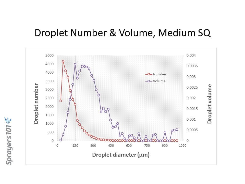
Droplet size distribution by number and volume from a Medium spray. Note the majority of the droplets are small, but the majority of the volume (dose) is in somewhat larger droplets.
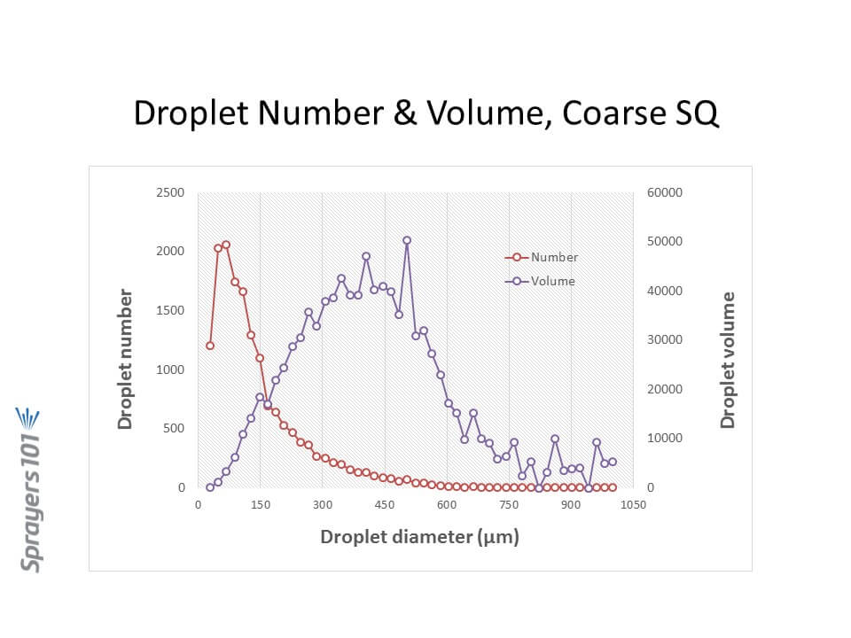
Droplet size distribution by number and volume from a Coarse spray. Like in the Medium spray, the majority of the droplets are small although there is fewer of them. The majority of the volume is in intermediate sized droplets.
Droplet size distribution by number and volume from a Very Coarse spray. While the majority of the droplets are small as in the finer sprays, their overall number is sharply reduced from the finer sprays. The volume is now in the largest droplet sizes.
Let’s focus on hydraulic nozzles, by far the most common in agriculture.
Spray Pressure
Spray pressure is a useful tool for controlling droplet size from any hydraulic nozzle. Need a finer spray? Add pressure. It is also the basis for the age-old recommendation that lower pressures are a good tool for reducing drift.
We impose practical limits on the upper and lower range of recommended pressures based on several other factors, chief among them the spray pattern.
Spray patterns of a certain width, or angle, are required for proper pattern overlap. The convention is to space hydraulic nozzles at 15 or 20 inch intervals along a boom, and operate them at about 20” above the target. Boom height values will depend on the fan angle of the nozzle and the degree of overlap required. For low-drift flat fan tips, a minimum 100% overlap is best. With 100% overlap, the spray pattern width at target height is twice the nozzle spacing. With this approach, at any point under the boom, the target receives droplets from the closest two nozzle patterns.
Pattern angles are published by manufacturers, but in practice, angles often differ from those values and can vary with spray formulation. Importantly, they tend to become narrower at lower pressures. The exact pressure at which this happens depends on the tip design, but experience shows that pressures below 20 psi for conventional nozzles, and 30 to 40 psi for low-drift nozzles, result in poor (too narrow) patterns. Narrow patterns reduce overlap, resulting in poor distribution.
TeeJet AI11003 at 20 psiTeeJet AI 11003 at 80 psi
We might also limit pressures at the upper end, based on drift potential. Most conventional flat fan nozzles, for example, drift excessively at pressures above 60 psi or so, hence that limit.
Low Drift Nozzles
Low drift nozzles were quickly adopted by applicators due to their ability to reduce drift and thereby widen the window of safe spray application. They work by using a two-stage design (often called “pre-orifice”) to reduce the internal operating pressure of the tip. The pre-orifice, the original liquid inlet, is round and sized for the nominal flow of the tip. The exit orifice is eliptical in shape and has a larger flow capacity than the pre-orifice, by about 1.2-fold to 2.5-fold. The larger exit creates an internal pressure drop, so the pattern formation produces larger droplets as though the operating pressure had been reduced. Most modern low-drift tips also introduce air into the nozzle via a built-in venturi. This further suppresses the formation of driftable droplets and introduces air into the interior of the nozzle, adding some pressure back to the system.. The Albuz AVI nozzle schematic below explains the venturi design.
Cross-section of the Albuz AVI venturi nozzle.
The tapered channel inside the nozzle is a venturi, which draws air into the nozzle via integrated ports. When low-drift nozzles are operated beside conventional nozzles at the same pressure, low-drift nozzles produce much fewer driftable fines, and also more larger droplets.
But while the two-stage design is useful for managing drift, it also conceals the actual operating pressure of the exit orifice in these tips. The exit orifice is important – it is the part of the nozzle that does the atomizing and that forms the pattern.
Let’s illustrate the pressure inside a low-drift tip by operating an air-induced low-drift nozzle at 60 psi. This nozzle has a pre-orifice size of 03 (0.3 US gpm at 40 psi, blue) and an exit orifice size of 06 (0.6 US gpm at 40 psi, grey). The operator sees 60 psi on the gauge. What is the exit orifice pressure?
The exit tip has twice the flow-rate of the pre-orifice, and therefore operates at one quarter the pressure, or 15 psi. Recall the square-root relationship between flow rate and pressure.
The relationship between spray pressure and flow rate. Doubling the flow rate requires a quadrupling of pressure
That’s not the whole story. The internal venturi is drawing additional air into the nozzle chamber, and depending on the operating pressure, this could be from 5 to 15 psi. The amount added depends on the specific nozzle, its flow rate, and its pressure. Let’s add 10 psi in this case. The exit tip is actually at 25 psi.
Now let’s assume the pressure gauge reads 40 psi, and that the venturi generates 5 psi additional pressure. The actual exit orifice pressure is now only 15 psi. This is at the lower limit at which a spray is atomized, and at which a good pattern can form.
Our general recommendation with venturi-style low-drift tips has been to avoid pressures below 30 or 40 psi for that reason. We’re trying to prevent the spray becoming too coarse for adequate coverage, and also to prevent the spray pattern from collapsing.
The upside of this design is that the same principle allows for much higher-pressure operation without creating excessive drift. These types of nozzle can, in fact, be operated at 70 to 90 psi without becoming very drift-prone because the pressure at which the spray liquid is atomized is likely only 30 or 40 psi (the actual exit pressure and drift potential will depend on the nozzle and the formulation).
Speed Range
A low-drift nozzle with a pressure operating range from 30 to 90 psi (i.e., 3-fold) would have a flow rate range of 1.73 (i.e., the square root of 3 due to the square root relationship of flow rate and spray pressure). This means that the fastest travel speed (at 90 psi) would be 1.73 times the slowest travel speed (at 30 psi).
A conventional nozzle operating between 20 and 60 psi would have the same travel speed range. So why don’t we just do that? The main reason is that the two-stage design lowers the overall amount of drift substantially, something a conventional nozzle can’t achieve even at very low pressures.
A second reason is that even at high pressures, a two-stage design will likely drift less than an conventional nozzle. This is still the case if the conventional nozzle is operating at low pressures. Any spray quality chart comparing spray qualities of conventional and low-drift tips will demonstrate that.
Pulse Width Modulation
PWM uses a solenoid to intermittently shut off nozzle flow, between 10 and 100 times per second (Hz) depending on the manufacturer. This has implications for nozzle design because the nozzle must not leak liquid during the brief off-cycle. If it does, the small amount of liquid leaving the nozzle will not only not atomize properly, it will also cause a pressure drop within the nozzle which must be replenished with the next on-pulse. This will mean the on-pulse will operate at a lower initial pressure, affecting pattern development and atomization. For this reason, venturi-style low-drift nozzles have not been recommended with PWM. The venturi provides an alternate exit for air or liquid, compromising nozzle performance.
And yet, some venturi style nozzles do, in fact, produce acceptable patterns with PWM according to the nozzle manufacturers. This goes to show that nozzle design can continue to evolve to provide the best in drift reduction technology with PWM. Design for PWM suitability should be at the top of nozzle manufacturers’ agendas.
Nozzle design continues to evolve. But in the foreseeable future, spray pressure will continue to control pattern width and droplet size. That’s why understanding the pressure limits of any specific nozzle type, and maintaining pressure within those limits, is so important in any spray operation.
The introduction of dicamba and 2,4-D tolerance traits in corn and soybeans was accompanied by an unprecedented emphasis on spray drift management by the registrants. Product label statements for 2,4-D choline and the new formulations of dicamba emphasize spray drift control to a greater degree than previous products.
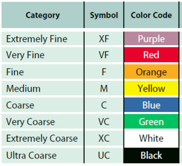
In Canada, labels make prominent reference to the appropriate “spray quality”, a term referring to an internationally standardized droplet size classification (ASABE S572.2). In this standard, the droplet size spectrum produced by a nozzle is communicated using terms such as “Medium”, “Coarse”, “Very Coarse” etc., and used to describe the potential for spray coverage and spray drift. Spray qualities are colour coded for easy recognition.
An example of this label language is shown for Enlist Duo below:
“Droplet Size: Apply as a coarse to extremely coarse spray (ASABE S572 Standard). Use drift reducing nozzle tips in accordance with manufacturer directions that produce a droplet classification of coarse to extremely coarse to significantly reduce the potential for drift.”
Although spray qualities are voluntarily measured and published by most nozzle manufacturers, their appearance on the label makes their use a legal requirement. This is because the Pest Management Regulatory Agency (PMRA) conducts a risk assessment which assumes, in this case, that a Coarse spray quality supports certain calculated buffer zones (15 m in this case) to protect sensitive ecosystems from Enlist Duo damage.
The use of coarser sprays can be used to reduce this buffer zone somewhat, in accordance with an on-line “Site-Specific Buffer Zone Calculator” published by the PMRA.
The challenge for applicators will be to determine the spray quality of their current application method. Here’s a relatively simple three-step process to find out.
Step 1: Identify the nozzles currently on the sprayer.
It seems basic, but it’s surprising how many applicators can not name their spray nozzle. If unsure, closely inspect the nozzle, looking for the manufacturer’s name, the nozzle model, and its flow rate. Most nozzles will have this information printed right on them. Here are pictures of the most common nozzles. Can’t find the info? Have a look at this article for websites with pictures.
Major manufacturers include Hypro (John Deere via private label), Agrotop (marketed by Greenleaf in North America), Hardi, Lechler, TeeJet, Wilger, and Billericay Farm Systems (Air Bubble Jet). Manufacturers produce many models, but most are easily identified by a series of letters and numbers. For example, all nozzles will be offered in several fan angles (80º and 110º are most common), and flow rates (in US gpm).
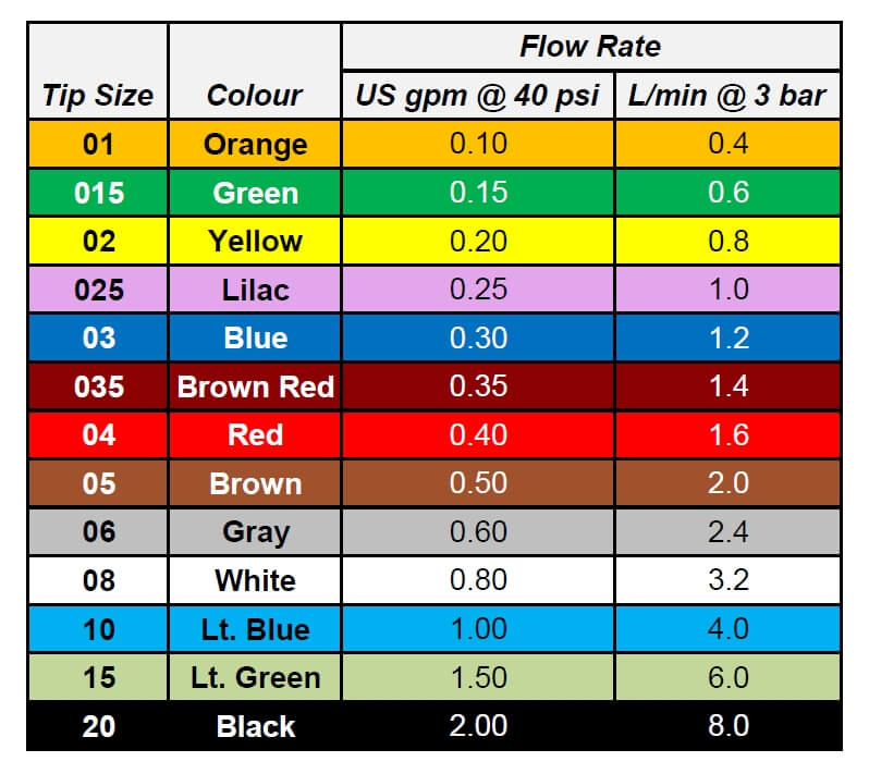
To be more helpful, flow rates are colour coded according to an international standard. This table shows the colours and lists flow in US units in (gpm at 40 psi) and metric (L/min at 3 bar).
The combination of series of letters or numbers shown on nozzles follows a relatively consistent pattern: Fan angle and flow rate arranged as 11003 or 03-110. In this case, the nozzle produces a 110 degree fan and has a flow rate of 0.3 US gpm. The use of US gpm at 40 psi to designate flow rate is an international standard.
The nozzle model is frequently inserted into this stamp, and is manufacturer specific. For example, TeeJet may include “AIXR” in its stamp, and Agrotop may include “TDXL”. Hardi’s MiniDrift is abbreviated MD. Some nozzles may not list their fan angle. Others (Air Bubble Jet) are blank, creating a mystic aura of superiority. Others leave the information printed on the nozzle cap.
A bit of experience is very helpful, especially with John Deere nozzles, where the nomenclature inexplicably eliminates the first digit of the 110 or 120 degree fan angle. So the JD 11004 is labelled “1004”. That’s a bit like saying “my truck sas a 50 engine”, when you mean it has a 350. How’s a city person supposed to know you don’t mean the trusty old 250 straight 6?
Step 2: Obtain spray quality information on the nozzle.
Most manufacturers publish the recommended pressure range and the spray quality of their nozzles. This information can be found in their product catalogues, or on their websites, or in smartphone apps.
Although the designation of Spray Quality is governed by an international standard that is designed to standardize droplet sizing among various labs, we do see some variation in results. Part of this is due to the continued evolution of the standard, requiring manufacturers to re-do some tests, or at least re-analyze their data. For example, ASABE S572.3 was released in conjunction with ISO25358 which changed the boundaries for the coarser sprays. These changes are beginning to be seen in the newer catalogues.
Another problem is that testing is done with plain water. It is well known that the use of certain formulations or adjuvants can affect spray quality. Currently, the standard does not address these effects, and data should be used with some caution.
Step 3: Identify the expected pressure for a given travel speed and water volume.
The same catalogues or websites that publish spray quality also produce charts that list the expected spray pressures at various travel speeds and water volumes.
Becoming familiar with using these charts enables the applicator to predict the spray pressure the nozzle will be operating at. For example, if an applicator intends to apply 10 gpa using a yellow (02) nozzle, this table shows the following: The nozzle will be operating at 30 psi at 5 mph, at 40 psi at 6 mph, at 60 psi at 7 mph, at 70 psi at 8 mph, and at 90 psi at 9 mph. The applicator should know the nozzle’s spray quality at each of those pressures.
Nozzle sizing follows a slightly different procedure for Pulse-Width-Modulation (PWM) systems, requiring the nozzle to be over-sized about 30% or so. Since the majority of new sprayer sales now include PWM, we’ve prepared a special article just for this system here.
Travel speed and/or spray volume should be adjusted to ensure the sprayer operates at a pressure which creates the desired spray quality. In other words, the pressure gauge should be used as a speedometer. If the nozzle model or size doesn’t produce the desired results, the applicator should consider changing nozzles. Once the right combination of factors has been determined, the spray pressures that created the label-required spray quality should be noted. From that point, the applicator can choose travel speeds that maintain the necessary pressure range.
Summary
It is up to applicators and industry representatives to ensure that herbicide products are applied according to label requirements. We expect significant scrutiny on spray drift from new products and need to ensure that proper application methods are used at all times. It’s important that everyone understands just how to do it.
Dr. Scott Bretthauer (U. Illinois) gives a nice summary in this video by Precision Labs:
One of the greatest threats to lost return and non-target plant damage in spraying is drift. Spray applicators have to be conscious of all kinds of factors that affect the risk of drift, including wind speed, boom height, potential inversions and, of course, spray quality.
Tom Wolf zeroes in on spray quality, explaining what it means and how a given nozzle is categorized. Wolf also suggests which categories of quality (from Very Fine to Ultra Coarse) should rarely be considered in agricultural applications, and where spray applicators can find information to aid in one aspect of the crucial decision making process surrounding spraying.