“I’m an organic apple grower with constant nozzle-clogging problems. These problems occur when we use wettable powders such as micronized sulfur and Surround WP. We always premix before adding to the tank through its strainer. Our airblast sprayers have towers and employ mechanical agitation. The nozzle/filter combo is TeeJet TXR8001K Ceramic Conejet Visiflow Hollow Cone spray tips with TeeJet 4514NY10 50-mesh nylon slotted strainers. The nozzle strainers rarely make it through a full tank without having problems. Do I need to add an additional level of filtration or is there something that I’m missing?”
A clogged slotted strainer inside the nozzle body. Note that the inners of the check valve seem clear (a good thing).A clogged slotted strainer.
You can almost feel the frustration. When I receive grower enquiries, I first turn to the library of articles on Sprayers101 as well as the Airblast101 textbook. I was surprised to discover that we didn’t have anything that addressed this issue directly. So, I checked through university extension and industrial resources. Ultimately I couldn’t find what I was looking for, so let’s correct this oversight.
Possible causes
There may not be a single reason for why nozzles plug. It might be a combination of the following factors:
1. Product choice
While any tank mix can create clogs if they prove to be physically incompatible, there are two formulations that have a reputation for clogging nozzles.
Wettable powder (WP) formulations such as micronized sulfur and diatomaceous earth are notorious for clogging nozzles. WPs consist of a finely ground solid active ingredient often combined with wetting and bulking agents to help hold them in a dilute suspension. They tend to be dry products rather than liquids.
In a similar vein, suspension concentrate (SC) formulations also consist of a finely ground solid active ingredient, but this time they are suspended in a liquid and kept dispersed in the sprayer tank by wetting agents, dispersants, and thickeners. These formulations are known as “flowables” or “suspensions”.
By the way, for those thinking he should change products, he already uses Kumulus DF (or Microthiol Disperss), which are reputedly the least troublesome formulations… and smell better than other sulfurs.
2. Mixing practices
Pre-slurries are sometimes prescribed for SCs. I personally feel that pre-slurries create exposure risks and more things to clean, but this opinion is moot in the case of WPs: Micronized sulfur and diatomaceous earth are not soluble. They’re particles that are held in suspension by fluid flow or agitation, so there’s no point in a pre-slurry.
For those readers that cook, consider the corn starch metaphor. You’re making a sauce, and you choose to thicken it with a pre-slurry of corn starch and water. The particles disperse, but do not dissolve, so if you fail to use it immediately they settle to the bottom of the container. They must be forcibly scraped up and resuspended.
3. Agitation
Best practice is to fill the tank at least ½ full of water and engage agitation before you add anything. To extend the cooking metaphor, you want a simmer but not a rolling boil. Once filled, never stop agitating or WPs and SCs will settle and may not resuspend uniformly, if at all.
Your sprayer design may affect matters. Some hydraulic agitation systems flag if they have undersized pumps. If your pump is busy sending flow to the nozzles, it may not have sufficient capacity to run the agitation. When your sprayer is “empty”, is there a thick accumulation at the bottom? You may have insufficient hydraulic agitation. Mechanical (paddle) agitation does not suffer this issue because it is direct-driven off the PTO. Read more here.
4. Clean-out practices
Perhaps plugs are occurring because of the previous tank, not the current tank. WPs can leave a buildup of settled pesticide in the tank, suction strainer and nozzle strainers. If you aren’t diligent about rinsing at the end of each day, products will settle and harden. Micro sulfur particles, for example, are less than 10 µm in diameter and harden into a flakey shell that can break loose and cause plugs.
5. Flow restriction
Several things can restrict flow. Elbows, bends and fittings can increase friction, reducing flow. The greater the distance a fluid needs to travel, the more flow is reduced. The greater the head (a pump’s head is the maximum height that the pump can achieve pumping against gravity), the more flow is reduced. There is an excellent description of this relationship here.
So, if an operator is using nozzles with a particularly small orifice, plus nozzle strainers, on a vertical boom, liquid flow will be reduced. This allows particles to fall out of suspension and settle, forming further restriction to flow and eventually, plugs.
Possible solutions
Now, armed with these potential causes, let’s return to the grower. After some back-and-forth, he clarified that the clogs were a problem, but restricted flow was worse. An operator will stop to clean or replace a plugged nozzle, but may not notice reduced flow. This has the potential to affect several rows as well as leave unsprayed product in the tank.
My first proposal was to increase nozzle size. An ’01 tip is very, very small and even with slotted strainers (as opposed to mesh), that’s a lot of restriction. I suggested recalibrating for larger tip orifices. This is a rather involved process, but options included using every second nozzle (as long as there were no gaps in coverage), and/or dropping pressure, and/or increasing travel speed (as long as the spray still reached the tree top and canopy centre). I shared this Excel outputcalculator to help with the process.
Failing that, we discussed a plumbing project. Section 5.2.1 of Airblast101 describes a way to create a self-cleaning line filter that replaces nozzle strainers. That means instead of climbing a ladder to pull tips off a tower to reach the strainers, all filtration is conveniently located at ground level for easier (and more frequent) cleaning.
The outcome
The grower felt the numbers worked best running orange 02 TXR’s in every second position. He ordered new 50 mesh slotted nozzle strainers. His new operating parameters would be 5 nozzles/side, at 8.2 bar (120 psi) and 5.1 km/h (3.2 mph) for a total 51.5 L/ha (55 gpa). He noted some incompatibility issues running Braglia nozzle bodies (spec on his Rears sprayer), TeeJet TXR’s, TeeJet slotted strainers and TeeJet CP20230 caps. That was an important observation, and you can learn more about it here.
We felt good about this, but while there was an improvement, it didn’t solve the problem. There was still strainer clogging after the first tankload. So, he added inline filters and removed the tip strainers. The result:
“Yesterday I sprayed over 350 pounds (over 1,000 gal) of Surround WP and had no issues. I’m really excited about this new setup – it looks very promising. I’ve attached more pics if you’re interested (I don’t spend a lot of time scrubbing sprayers until after Surround season). Thanks again for all your help in this matter. – Joe Fahey, Peck & Bushel Fruit Company”
A 50 mesh inline filter assembly with a 1/4 turn ball valve for quick flushes.New filter plumbed and secured. Note the anti-rub wrap on the line – always a good idea.The new loadout. 02’s in every second position, with no tip strainers, and a new inline filter on each side of the sprayer.
Fantastic. Thanks to Joe for letting me share this story. Hopefully his experience will help you diagnose and solve any flow or nozzle plugging issues in your own operation.
Happy Spraying.
Epilogue
This article elicited some interesting comments. I’ll share two:
One grower proposed switching from a low profile axial sprayer to an air-shear system (there are a few examples here). In this case, the grower had a European make with hydraulic agitation. The grower re-plumbed theirs by installing a bigger pump and swapping the sparge system with a 3/4″ pipe oriented toward the bottom to sweep it out. When mixing, the agitation valve is left wide open. He says he doesn’t even bother with a tank basket; he dumps the Surround (as much as 2 x 50 pound bags in 1,000 litres) and has no plugging issues.
Another grower with considerable boom-sprayer experience was genuinely surprised this was even an issue. Self-cleaning filters have been commercially available for more than 30 years and most boom sprayers have them. This is a comment on the stagnation of the North American low-profile radial airblast design. Perhaps the long life of these sprayers (sometimes 40 years of service) makes iterative change slow, or perhaps most operators aren’t aware of new features, or perhaps change is a risky proposition in such high-value crops. This is a shame given that the first optic sensors were installed on airblast, not broad acre field sprayers. That comes as a surprise to many. But it seems to have been the exception and not the rule.
This article has been modified with kind permission from an article on Retrofit Parts.
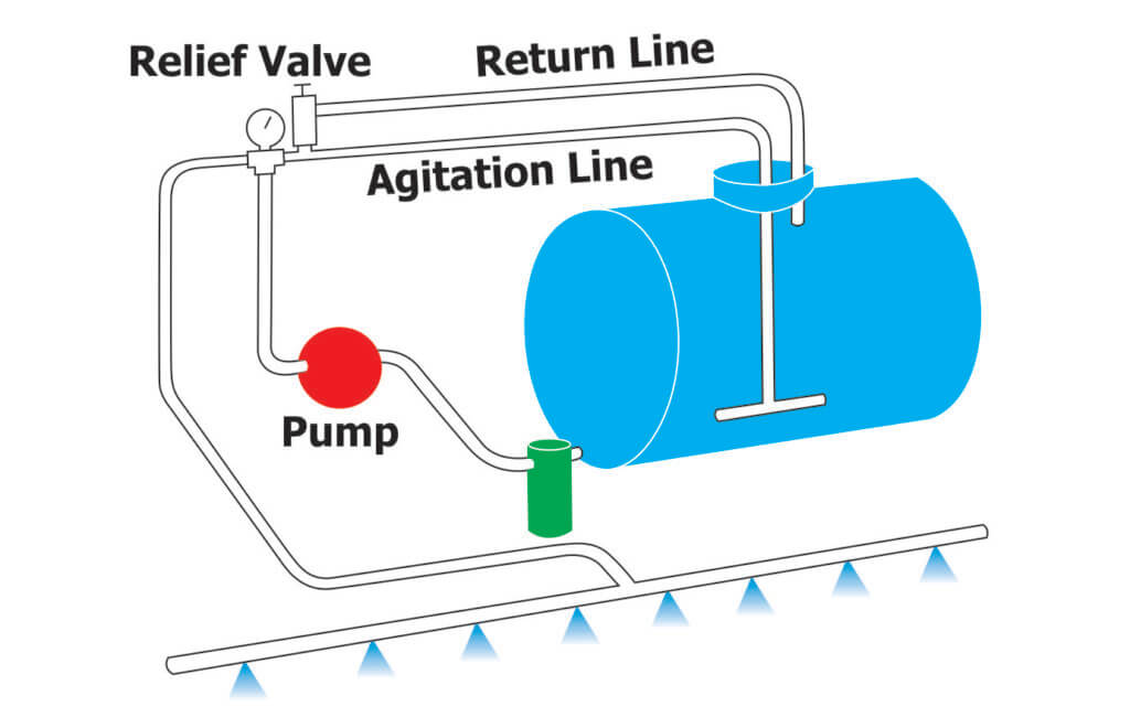
Liquid pressure in an agricultural sprayer must be controlled so as to apply the correct volume of spray per hectare.
For sprayers that use positive-displacement pumps driven by the tractor’s power take-off, higher flow rates are produced than are actually required. Part of the pump’s output is therefore returned to the tank through a bypass line (aka return line), and spray pressure is controlled by a regulating or relief valve in this bypass line.
Ordinary regulators can maintain a constant pressure if the volume of liquid does not vary too much. But when it’s necessary to shut off part of the spray-boom in order to avoid double-spraying, (or in the case of an airblast sprayer, shut off one side), there is a large increase in the bypass flow and this causes the pressure to rise unless special compensating valves are fitted and correctly set.
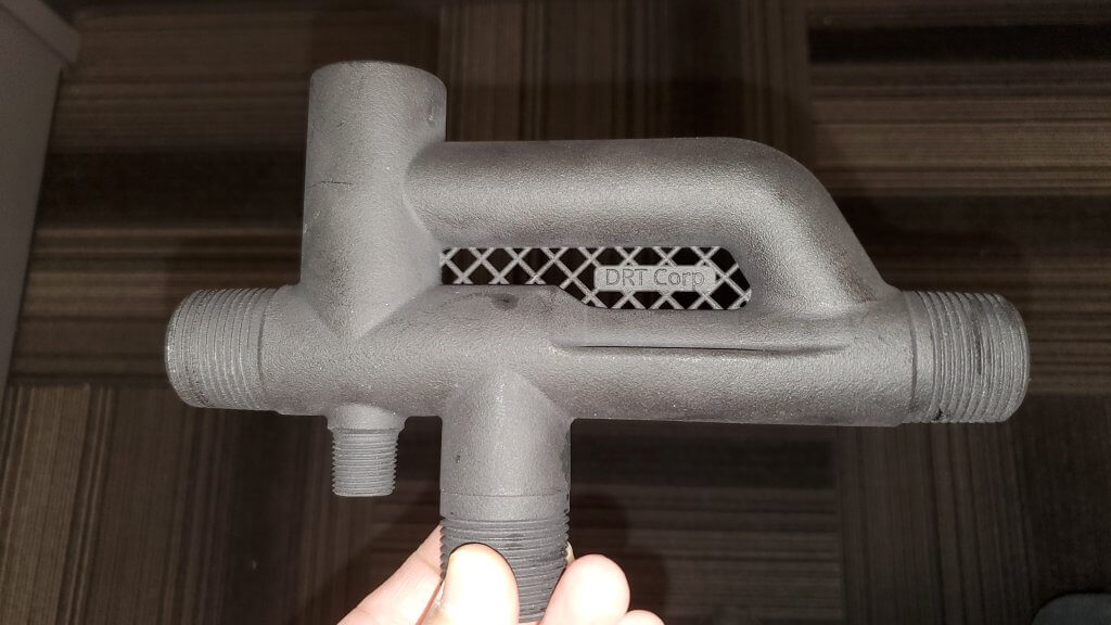
Ramsay (or Ramsay Nocton) pressure-sets automatically maintain constant pressure over a far wider range of variation in flow-rate; for example the bypass flow through Retrofit’s model can increase from 1 to 100 L/min with an increase in pressure of only 0.2 bar (~3 psi). Lechler also offers 1 1/4″ and 2″ thread models called “AirPress” with different flow and pressure metrics. Each model allows the spray boom to be shut off with ordinary diaphragm check valves and also allows the operator to change gear (and so change the pump speed) without affecting the pressure.
Ramsay pressure-sets are non-electric, and the only moving part is a flexible diaphragm. The working pressure is set by inflating the pressure-set with air.
It is often desirable to vary the pressure while spraying, either automatically or manually. This can be done by a small electric air compressor and two valves which respectively increase or reduce the air pressure behind the diaphragm. These valves may be actuated by an electronic ground-speed-related system, or controlled manually by the operator.
How it Works
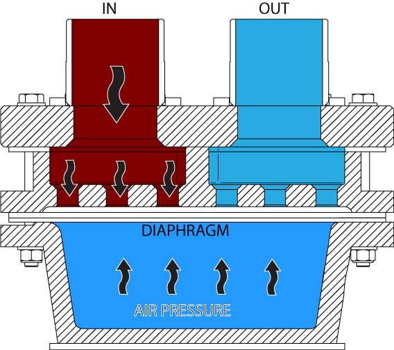
When the pressure in the IN chamber exceeds the air pressure it pushes the diaphragm away from the holes (as shown below) allowing some of the liquid to pass across to the OUT chamber, thus relieving the pressure (A backing plate, not shown in the diagram, prevents the diaphragm from being stretched too far).
A Ramsay valve with the diaphragm closed. Pressure in the IN chamber does not exceed the air pressure behind the diaphragm.
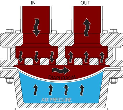
In practice, the diaphragm opens just as far as it needs to for the liquid pressure and the air pressure to come into equilibrium. When a boom is shut off and more flow needs to return to the tank, the diaphragm opens wider and remains in equilibrium in its new position.
A Ramsay valve with the diaphragm open. Pressure in the IN chamber exceeds the air pressure behind the diaphragm and can flow past to the OUT chamber.
Consequently, as long as there are no restrictions in the line back to the tank, the pressure remains constant even when there are large changes in pump speed or spray speed-boom demand. Pressure varies only slightly as the compression of the air in the air-reservoir varies with the movement of the diaphragm.
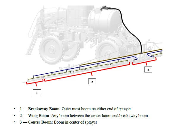
If you read this site, you know we’re fans of recirculating booms. We love them for three reasons:
They save money and waste by recovering spray back to the tank during priming and rinsing
They make boom cleaning easier by eliminating boom-ends
Most require individual nozzle shutoff, which makes for better sectional control
If you’re new to the concept of recirculating booms, read more here.
Until recently, these booms were only available on sprayers imported from outside North America (Horsch, Amazone, Agrifac to mention three), or via France’s Pommier booms that have been available as retrofits for many years. In 2018, Agco introduced their Liquid Logic system on the Rogator line, becoming the first North American manufacturer to offer a recirculating boom at the factory. Pattison Liquid also offers Recirculating booms as standard equipment on their Connect Sniper pull-type sprayer.
In the meantime, three boom retrofit kits and one sectional conversion kit have become available.
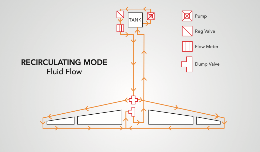
Arag Australia‘s BRS (Boom Recirculation System)
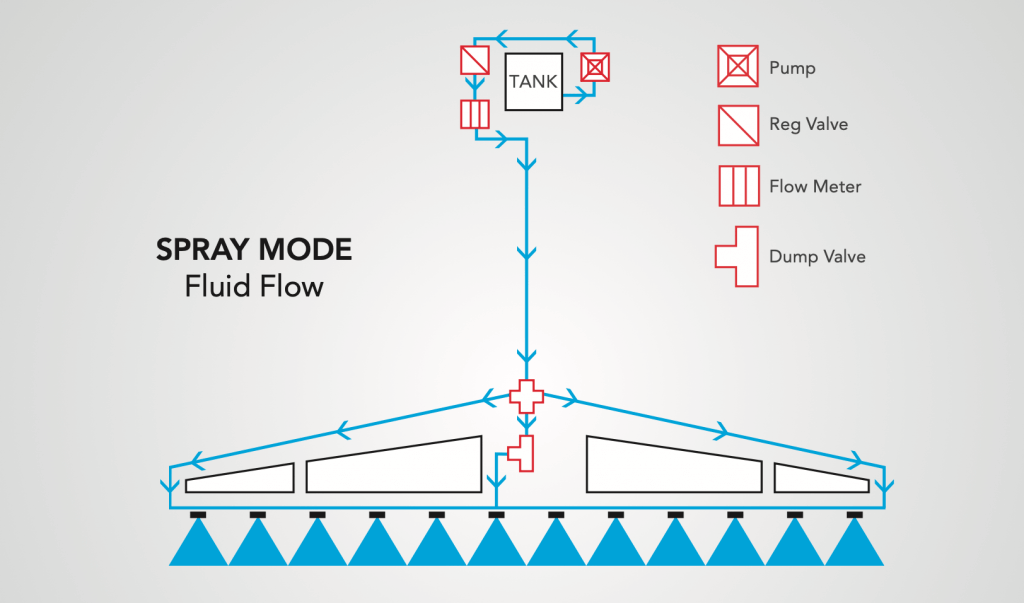
The first was developed by Arag Australia, and is available there via Nozzles Online, and in Canada through Nozzle Ninja. Designed for John Deere R-Series and Case Patriot sprayers, the kit uses the existing line that feeds liquid to the outermost section and simply extend that line to the end where it enters the boom via two installed elbows. The liquid returns to the centre via the installed boom sections which are connected together by removing the boom end cap (or “aspirator” for John Deere) and replacing the gap with a section of hose. Back at the centre rack, the liquid from both booms meet in the middle. At this point, a three-way valve gives the choice to return the spray to the tank, or to receive pressure from the pump. There is also a manual valve that allows the return to be dumped for safe disposal.
Arag Boom Recirculation System (Spray Mode)Arag Boom Recirculation System (Recirculation Mode)
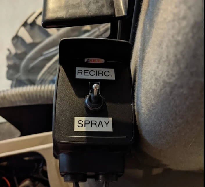
The system does not tie into the sprayer’s electronics. instead, it adds a switch in the cab that the operator uses to switch from spray mode to recirculation mode. The switch is not activated at the end of each swath, but instead to prime or flush the boom.
A switch is added so the user chooses recirculation or spray mode. The boom would recirculate to prime or flush, and remain in spray mode during the spray operation.
Raven
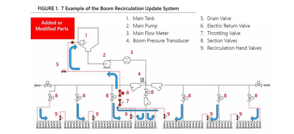
Raven offers a recirculation kit for 3000, 4000, and 5000 series Case Patriot sprayers with Aim Command HD and an ISOBUS terminal. The approach is slightly different, as they retain the pressure feed through individual sections but also tie the sections together so the spray is returned to the tank. By including a shutoff valve between each section, the system retains the option to use conventional sectional control for high flow situations, or to isolate a section should a leak occur. The system can be configured and controlled from the sprayer monitor, either a Viper 4+, CR7, or CR12.
Raven Boom Recircualtion System schematic (from Raven manual). Note the retention of section valves and the addition of manual valves between sections.
John Deere
On March 2, 2021, John Deere announced a 2022 factory option called Pressure Recirculation and Product Reclaim. The system keeps several existing sections and adds two steel lines the flull length of each boom wing. One is for supply, the other return. As these lines approach a section, the supply is fed to one end of the section and the return is connected to the other end. On a 120′ boom, there are five recirculating sections, two on each wing and the centre.
This approach adds one more line than the other designs, and this line will hold materials that ultimately need to be cleaned, flushed, and possibly dumped or sprayed out for cleanout. A possible reason for the extra line is the ability to deliver 220 gpm to the boom, an advertised feature of John Deere high flow booms that may come in handy for topdressing liquid fertilizer. These levels of volume are not needed for pesticides.
John Deere Boom Recirculation and Reclaim. Top two lines are supply and return and extend the length of each boom wing. These connect to the existing sections on each wing, creating several smaller recirculating sections.
Latitude Ag
This Wisconsin company has developed an innovative product that converts any existing plumbed section that contains boom ends into a recirculating section. It does this by incorporating a boom recirculation valve” (the “Merlin IC System“) into the original section feed line. Boom end caps are removed and replaced with sweeps and hoses that return flow to these boom valves. The flow from the boom ends is incorporated back into the sectional feed thanks to a venturi design in the recirculation valve.
A prototype of the Merlin IC System valve made by Latitude Ag
Advantages of this design include simplicity. No moving parts are required, the valve simply recirculates the flow from the boom ends automatically whenever that section operates. Existing sectional control, whether it’s by plumbed section or individual nozzle bodies, is unaffected. Flushing the boom with water is done with normal spraying. It takes some extra time to incorporate and dilute the contents of the boom end return lines but results in a clean boom and no section end residue. We’ve seen the results of testing and agree that it works.
This product does not allow boom priming without spraying. However, a key advantage is that it can be used with direct injection since no product is returned to the tank. Latitude Ag says it will provide the necessary flow sensor and software to make this possible. As of 2025, this system may no longer be commercially available.
Precision Planting ReClaim
ReClaim is capable of operating on a sprayer with or without individual nozzle shutoff. For conventional nozzle bodies containing the original spring-loaded diaphragm check valves, the concept is to drop the liquid pressure below the cracking point of the check valves so flow continues through the sections and back to the tank without engaging the nozzles.
Recirculation fittings are added to the end of each boom section. These feed into 3/4″ lines are installed on section ends, which in turn feed increasing diameter collector lines that eventually return all flow to the tank. Flow reaches the sections as before. When recirculation is turned on, flow exits the boom section through the new fittings and returns through 3/4″ lines to the centre of each section, where it enters 1” lines that take the flow to the center of each boom wing. There the flow in the 1” lines is combined moves to the center of the sprayer on 1.5” lines where it meets the flow from the other wing. From there, the flow returns to the tank through an electronic ball valve and 2” line. This system ensures no back-pressure and balanced flow from each section.
For some sprayer rate control systems such as John Deere, the pump won’t operate below about 20 psi despite operator settings. This means the priming or flushing procedure would trigger nozzles to spray if the bodies were fitted with spring-loaded diaphragm check valves. A pressure reduction kit (a second restrictor valve) is required to reduce the pressure sufficiently for ReClaim to work in these instances. More here.
ReClaim operates independently of any electronic control systems, relying on a toggle switch to initiate recirculation. When flow back to the tank is detected, a light indicates that recirculation is working, and the operator waits approximately 60 sections for a 120’ boom to circulate all volume back to the tank. Download the operator’s guide, here.
This system requires a lot of additional lines. A 120’ boom would require 120’ of additional 1” line and 60’ of 1.5” line. The manufacturer states that ReClaim adds about 14 gallons of volume that would need to be displaced back to the tank, adding to the standing volume. This volume can be circulated using solution from the main solution tank, or displaced back to the tank using flow from an existing clean water tank, or displaced using compressed air via an optional pneumatic port. It is not clear how spray mix in the ReClaim system can be removed from lines without returning it to the tank and draining it from there. Users should consider the additional surface area and volume that will have to be addressed during cleanout.
Do It Yourself
If none of the available options work for your sprayer, consider building your own system. Sprayer plumbing parts are available from the major manufacturers Banjo, Hypro, TeeJet, and Wilger. Wilger, in particular, has developed a nice suite of parts well suited to recirculating booms, including flanged sweeps and thin gauge steel booms, punched for nozzle bodies or unpunched to move product. See their support for DIY projects on this dedicated page: Wilger Retrofit.
Take Home
All these recirculation options improve the status quo of plumbed boom sections with boom ends. They should be considered essential equipment on sprayers.
Small-plot agricultural sprayers should have a pressure gauge on the wand or boom to ensure accurate application rates. Most are added after-market and the operator has the choice of buying liquid-filled or dry gauges.
Glycerine- or silicone-filled gauges are preferred because
they dampen pressure spikes, pulsation and mechanical vibration. Compared to
dry gauges, they are available in higher ranges and are less prone to moisture
problems (which cause corrosion, accuracy and visibility issues).
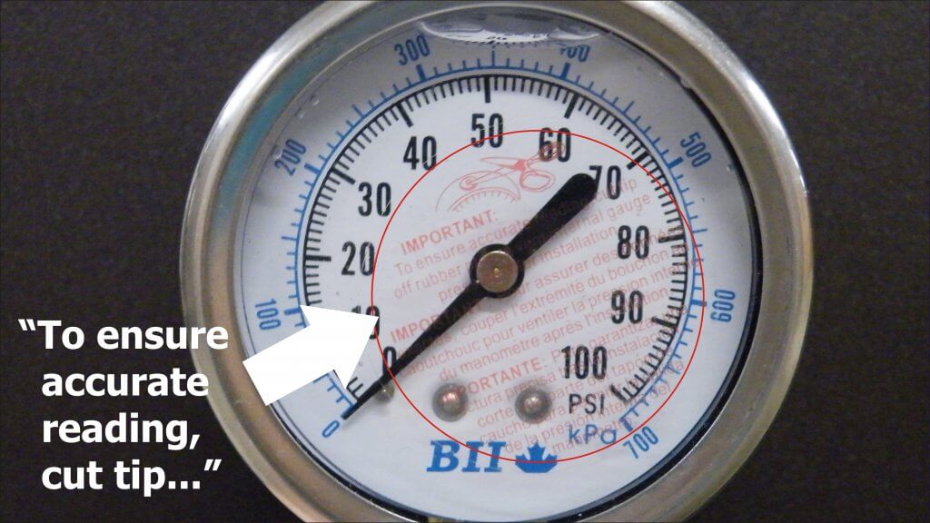
We use 100 psi (~7 bar) liquid-filled gauges for our handheld
sprayers. Only recently did we acknowledge the sticker affixed to the glass advising
the user to cut the nipple off the rubber plug located at the top. Preferring
to avoid messy leaks, we have always left it intact.
We wondered what impact, if any, this was having…
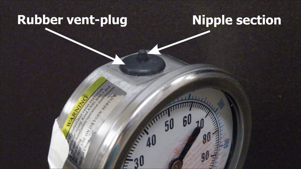
What are Vents?
Expensive gauges have mechanical vents that can be opened prior to use and closed to retain liquid when stored. More commonly, there is a rubber plug with a protrusion (referred to as a nipple).
Why Vent?
Mechanical, liquid-filled gauges are sealed to keep the
liquid in. When there are temperature fluctuations, the liquid expands or
contracts and creates “case pressure”. This exerts a force that interferes with
the pressure reading.
According to Marshall Instruments, case pressure can offset the accuracy by approximately 1 psi (0.07 bar) for every 35˚F (20˚C) temperature change, but is only noticeable when measuring lower pressures (0-15 psi or 0-1 bar). Nevertheless, they advise all gauges should be vented prior to use.
The plug can be removed to allow the user to refill the gauge, maintaining an air space of about ½” at the top of the window. If the nipple is cut off, the gauge is permanently vented and will leak if the gauge is not kept vertical.
Testing
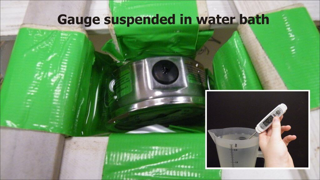
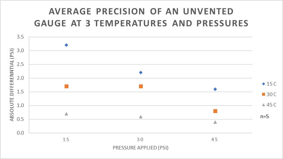
We performed an experiment to see if typical working temperatures had a practical impact on the accuracy of an unvented gauge. We suspended an unvented, liquid-filled gauge upright in a water bath at approximately 15˚C, 30˚C or 45˚C (59˚F, 83˚F or 113˚F) until it equilibrated. The high temperature may seem unreasonable, but gauges left in trucks on summer days get far hotter.
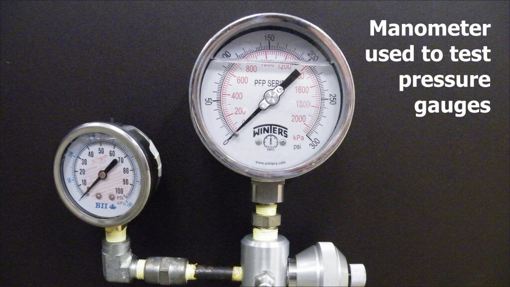
The gauge was quickly removed and placed in a manometer
(Ametek T-975) where it was subjected to pressures of 15, 30 and 45 psi (1 bar,
2 bar and 3.1 bar) and readings recorded. This was repeated five times. We then
vented the gauge and repeated the process.
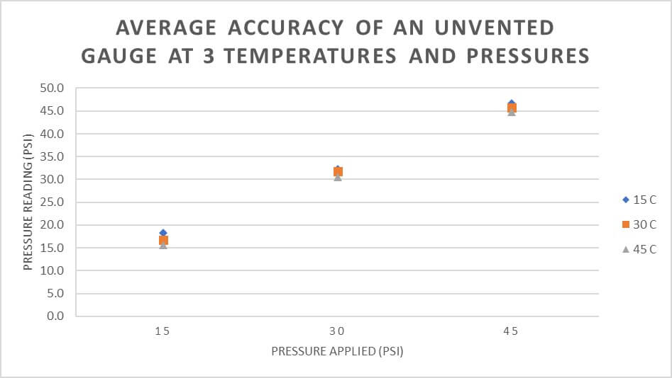
Results
At first, there appeared to be very little difference in average accuracy of vented and unvented gauges. Accuracy refers to the closeness of a measured value to a standard or known value. Perhaps there was some small increase in the pressure reported by an unvented gauge, but very little practical difference.
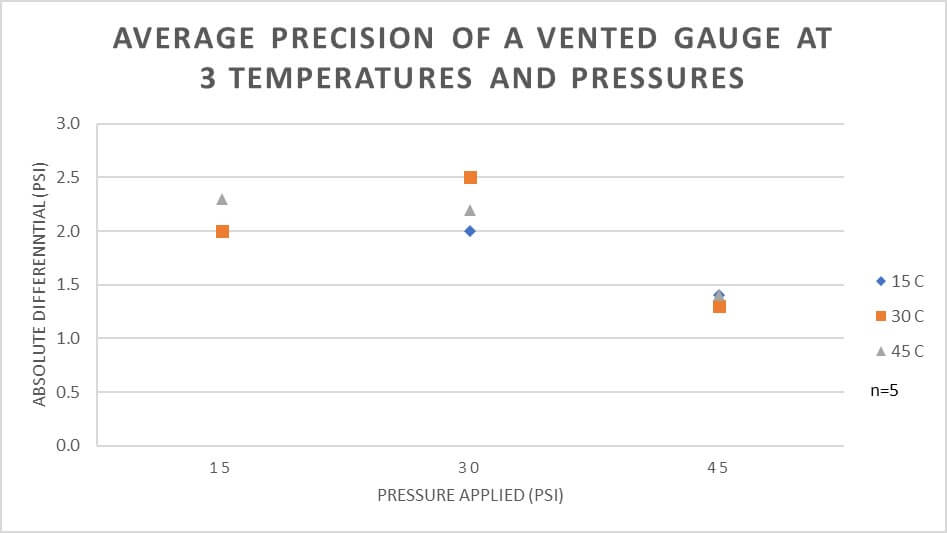
However, when we look at variability we get a different picture. Variability is a measure of precision, which refers to the closeness of measurements to one another. The graphs show that an unvented gauge has greater variability (less precision) at lower temperatures and lower pressures.
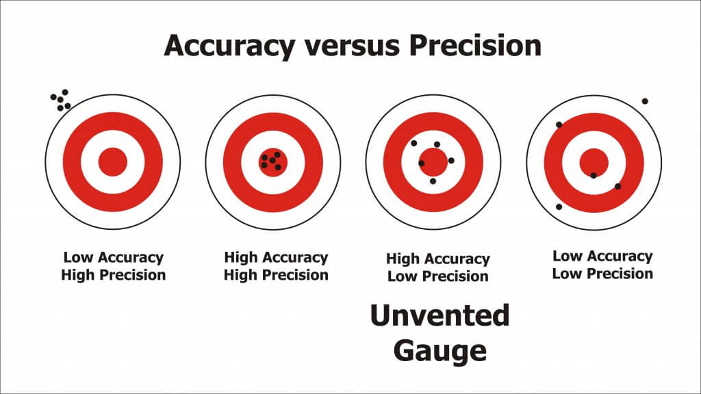
A good way to think of accuracy and precision is using the classic archery bulls-eye metaphor. The unvented pressure gauge is best represented by the third image, where it is accurate (on average) but not precise (variable).
Real-World Example
What does this mean in practice? Consider someone spraying a small plot using a TeeJet XR8002 nozzle on a CO2-powered hand boom at 30 psi. The difference in output between 30 psi and 40 psi is about 0.003 gpm / psi.
An unvented pressure gauge used on a hot day may read 1.5 psi lower, causing you to overcompensate and raise the pressure 1.5 psi higher than intended. That would result in 0.0045 gpm (0.5%) more applied. Compensating for an unvented gauge on a colder day might be closer to 0.009 gpm (1%) more applied.
Assuming a walking speed of 3.1 mph (5 km/h) and a swath of 20” (50 cm), the nozzle should emit about16.3 gpa at 30 psi. Unvented in the heat, that’s 16.7 gpa. At 33 psi, that’s 17.15 gpa. That’s almost 1 gpa more than intended. Potentially, the lack of precision could make a significant difference.
Conclusion
Liquid-filled gauges are preferred over dry gauges.
To ensure precision, the gauge should be vented prior to use.
Permanent venting on a hand-held sprayer causes leaks, which is a nuisance, so we suggest simply lifting the edge of the plug with a screwdriver or fingernail to vent the gauge prior to each use.
This work was performed by OMAFRA summer student, Aidan Morgan.
The pump is the heart of the sprayer and a key component for producing the flow of spray material and sprayer output. Because various spraying situations require different pressures and flow rates, using the correct sprayer pump is essential to achieving desired results. In addition to sprayer considerations, a pump must also be durable enough to withstand harsh chemicals that may cause excessive wear. Even though pumps with added chemical corrosion protection are more expensive, they are a popular choice because of their durability.
Roller, centrifugal, diaphragm, and piston pumps are commonly used to apply crop protection products. Centrifugal and roller pumps are typically used for low-pressure sprayers, and diaphragm and piston pumps are more popular when high-pressure sprayers are needed (i.e., vegetables, orchards, etc.). Less common pump types include squeeze, gear, and turbine.
Pumps are typically either ground driven or powered by main or auxiliary engines, power takeoff (PTO) shafts, or hydraulic pumps. The choice of pump depends on the material to be pumped and the capacity or volume needed. However, no particular type of pump is ideal for all purposes.
Sprayer pumps can be divided into two general categories: positive displacement and non-positive displacement. Positive displacement pumps (roller, diaphragm, and piston) maintain a flow output directly proportional to the pump speed. These pumps require a pressure-relief valve and a bypass line for proper performance. Non-positive displacement pumps do not have a proportional output flow to pump speed and do not require a relief valve and bypass line. The centrifugal pump is an example of a non-positive displacement pump style. A summary of common pump types and characteristics is found in the following Table (contributions from ACE Pumps Corporation, Hypro Pumps Inc., and CDS-John Blue Company).
Characteristic
Roller
Centrifugal
Diaphragm
Piston
Ground Driven Piston
Cost
Low
High
Medium
High
High
Displacement
Positive, self priming; Requires relief valve
Non-positive, needs priming; Relief valve not req’d
Positive, self-priming; Requires relief valve
Positive, self-priming; Requires relief valve
Positive, self-priming; Relief valve not reg’d. Runs off drive wheel and can be lifted on hydraulic-controlled applicators, or can be purchased with clutches to to disengage pump when flow is not desired.
Drive Mechanism
PTO, gas engines, electric motors
PTO, hydraulic drives, gas engines, electric motors
PTO, hydraulic drives, gas engines
PTO, gas engines, electric motors
Primarily ground-driven. Although less common, can be used with hydraulic drives, electric motors or gas engines.
Adaptability
Compact and versatile
Good for abrasive materials; Handles suspensions and slurries well.
Compact for amount of flow and pressure developed.
Wide range of spraying applications; Dependable
Wide range of spraying applications from clear liquids to suspensions. Very accurate regardless of ground speed or back pressure. Very dependable.
Durability
Parts to wear; replace
Very durable, not much wear
No corrosion of internal parts
Parts to wear; replace
Very durable. With basic care and maintenance, pumps can easily be in service 30 years or more.
Serviceability
Easy to work on, repair
Basic maintenance extends life
Low maintenance
Potential for high maintenance
Low maintenance
Pressure Range
up to 300 psi
up to 180 psi
up to 725 psi
up to 400 psi
up to 120 psi
Output Volume
2 to 74 gpm; high volumes for size; proportional to pump speed.
up to 190 gpm; High volumes for size and weight; Proportional to pump speed.
3.5 to 66 gpm; Proportional to pump speed.
up to 10 gpm; Proportional to pump speed, independent pressure.
0.5 gpm to 68.4 gpm.
Revolutions per minute
540, 1000
Requires speed-up mechanism. Very efficient at higher speeds; up to 6,000 rpm.
540
540
Ground-driven. Maximum 450 rpm.
Notes
Best choice by farmers.
If hydraulic-driven, no PTO required. Popular in commercial ag. applications. Running pump dry i s a problem.
Good for higher pressure requirements. Popular for horticultural applications. Pump can run dry.
Similar to an engine; Low capacity.
No gpa flow variation due to pressure or ground speed changes. No concern of electric failures on controllers or radar systems. Dependable accuracy.
Pump Efficiency
Regardless of the type of pump, the necessary flow rate must be provided at the desired pressure. Enough spray liquid should be pumped to supply the gallons per minute (gpm) required by the nozzles and the tank agitator, with a reserve capacity of 10 to 20 percent to allow for flow loss as the pump becomes worn. Unfortunately, pumps lose efficiency for a number of reasons, such as drive friction or leakage.
When estimating the pump horsepower needed for an application, efficiency (Eff) of 40 to 60 percent should be assumed. The horsepower (HP) required to drive the pump can be estimated by using the following formula:
HP = (gpm × psi) / (*1,714 × Eff) *Constant derived when converting gallons, minutes, pounds, and inches to horsepower.
Example: How much horsepower is required to run a pump if the maximum output is 50 gpm at 40 pounds per square inch (psi)? Assume a pump efficiency of 40 percent.
HP = (50 gpm × 40 psi) / (1,714 × 0.40 Eff) HP = 2.92
Because of inefficiencies of the drive units, electric motors should be approximately one third larger than the calculated horsepower. Gasoline engines should be one half to two thirds larger than the pump horsepower required. Ground-driven pumps that vary flow rates as ground speed changes are accurate and dependable; they are often used when applying high volumes of materials such as fertilizer.
Many pumps are PTO driven, but most modern spray pumps are hydraulic driven because of mounting versatility, ease of maintenance, and customization for individual sprayers. Charts are available to match pumps to various tractor hydraulic systems. You can access these charts by following the links to the following major pump manufacturers:
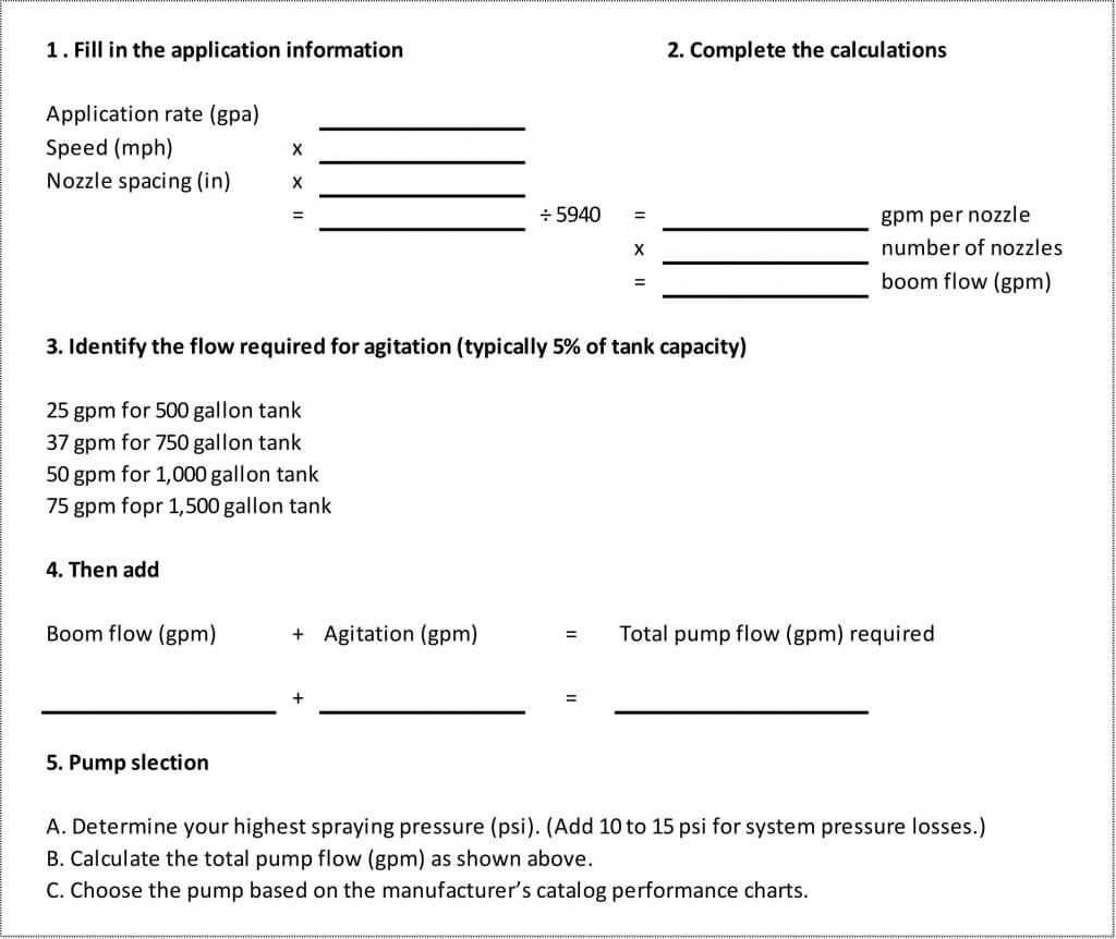
Proper pump size is an important consideration when selecting a sprayer pump. Requirements for nozzle capacity, hydraulic agitation, and overcoming the efficiency loss noted previously are essential points to consider. Nozzle capacity is determined by multiplying the number of nozzles on the boom times the output (gpm) of each nozzle for a specific application. Be sure to give consideration to the range of spray pressures that will be used for the given application. Agitation requirements typically account for another 5 percent of the sprayer tank capacity. Efficiency losses due to friction and pump wear may account for an additional 10 to 20 percent increase in the required flow rate. Spray pump manufacturers provide useful Web page worksheets to help determine pump sizes based on typical field application scenarios.
Manufacturers also make product guides available to help match sprayer pumps and hydraulic motors to the tractor’s hydraulic system (Table 2). A simple pump selection worksheet is provided at the end of this article.
No matter what type pump is used, it must be plumbed to route liquid from the pump to the spray boom with a minimum amount of restriction, a necessity for achieving the pump’s maximum rated capacity. The hoses should be the same size as the pump’s suction and discharge ports. Other recommendations include installing a pressure gauge and valve on the pressure side of the pump to measure the shut-off pressure and using a minimum number of elbows, fittings, and valves to reduce pressure losses.
Following these guidelines is necessary for delivering the highest pressures to the boom.
Pump Rotation
Pump rotation is critical for PTO and belt and- pulley driven pumps. The direction of rotation is always determined when facing the pump and drive shaft, and pumps are available in both clockwise and counter-clockwise rotation. Thus, when direct coupling shafts, the opposite rotation pump should always match the shaft. When mounting a pump with belts and pulleys, either pump rotation can be used to match the drive shaft rotation and the desired direction of the pump. Gasoline engine and electric motor shafts rotate in a counter-clockwise direction, and a tractor PTO shaft rotates in a clockwise direction.
Pump Types
Roller pumps are popular for small sprayers because of their low initial cost, compact size, ease of repair, and efficient operation at PTO speeds of 540 and 1000 revolutions per minute (rpm). Roller pumps are self-priming, positive displacement pumps, and a variety of models is available. Maximum outputs range from 2 to 75 gpm, and pressures range up to 300 psi.
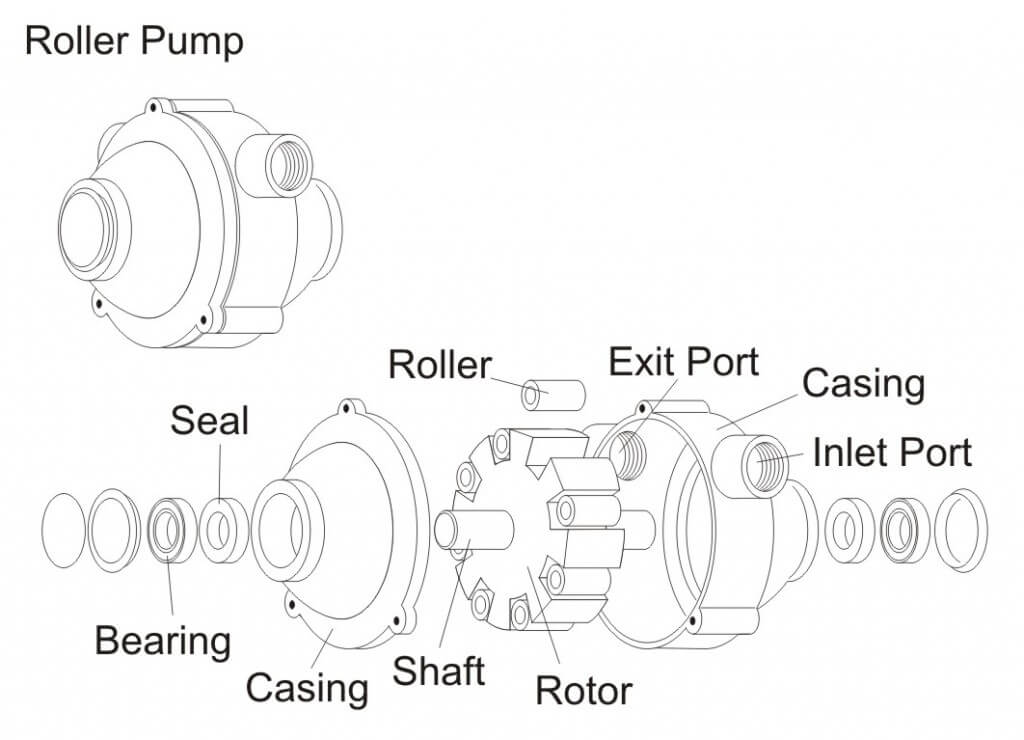
Figure 1 – Roller Pump
Roller pumps are usually constructed with cast iron or corrosion resistant housings (non-symmetrical in shape), rotors, four to eight rollers (either nylon, Teflon, or rubber), and seals (Viton, rubber, or leather). The type of material selected depends on the chemical being pumped. A typical roller pump is shown in Figure 1.
Nylon or Teflon rollers are the most resistant to agricultural chemicals and are recommended for multipurpose sprayers. Rubber rollers are preferred when the pump is used only for water solutions and wettable powder slurries at pressures less than 100 psi. Because sand and scale are abrasive to the rollers, the solution being pumped must not contain these materials. Polypropylene rollers wear better than either nylon or rubber rollers when applying weak solutions or solutions with little or no lubricating qualities.
Some operators have experienced problems with excessive wear of the rollers, especially when using wettable powders. Other operators have achieved long pump life by allowing the pump to run continuously when spraying with wettable powders, and by properly maintaining and storing the pump, including keeping abrasive materials out of the sprayer. Specific seal, roller, and casting materials can be selected for compatibility with certain herbicides, insecticides, fungicides, and fertilizers Consideration should also be given to the adjuvants used in the spray solution.
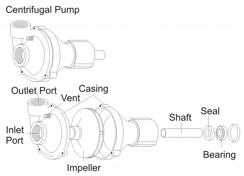
Centrifugal pumps are the most popular type of low-pressure sprayer. They are durable, simply constructed, and can readily handle wettable powders and abrasive materials. Because of the high output of centrifugal pumps (70 to 190 gpm), the spray solution can be agitated sufficiently even in large tanks at pressures up to 180 psi. The initial cost of a centrifugal pump is somewhat higher than that of a roller pump, but its long life and low maintenance make it an economical choice. Pump housings of cast iron, stainless steel, and polypropylene are advantageous because they withstand strong chemicals. Stainless steel pumps are ideal for use with glyphosate or other acid applications. Polypropylene pumps are lightweight and provide excellent resistance to corrosive chemicals. Figure 2 shows a typical centrifugal pump.
Centrifugal Pump – Exploded View.
Because centrifugal pumps are not self-priming, they should be mounted below the supply tank to aid in priming. In addition, a small vent tube should be installed from the top of the pump housing to the supply tank. This positive vent line allows the pump to prime itself by “bleeding off” trapped air upon starting and when the pump is not operating.
The inlet of a centrifugal pump should never be restricted. A partially clogged suction strainer, collapsed suction line, or a suction line with insufficient capacity causes a loss of pressure control and possible damage to the pump. Centrifugal pumps can handle small pieces of foreign material without damage, so a suction strainer is not always required. If a suction strainer is used, however, it must be capable of handling the large capacities of the pump with a minimal drop in pressure across the strainer, and it must be cleaned frequently. Typical centrifugal pump plumbing would place the strainer on the pressure side of the pump.
Centrifugal pumps for low-pressure sprayers can generate pressures of up to 70 psi when the impellers are running between 3,000 and 4,500 rpm. The output volume drops off rapidly when the outlet pressure exceeds 30 to 40 psi. The decrease in volume is an advantage because the nozzle pressure is able to be controlled without a relief valve. See Figure 3 for a typical centrifugal pump performance curve. The pump performance curve describes the relationship between flow rate and pressure for the actual pump.
Figure 3 – Centrifugal Pump Performance Graph
The need to operate at high impeller speeds requires a type of step-up speed mechanism when operating centrifugal pumps from PTO shafts. The simplest and least expensive of these mechanisms is a belt and sheave assembly. Other step-up mechanisms have planetary gears that are completely enclosed and mounted directly on the PTO shaft.
Another method of driving a centrifugal pump is with a close coupled, high speed hydraulic motor. Using the tractor hydraulic system to drive the pump keeps the tractor PTO shaft free for other uses. It is essential to consult manufacturer pump selection guides to match the proper pump to your tractor. Pumps can also be driven by direct-coupled gasoline engines when other drive mechanisms cannot be used.
Airplane pumps may be wind-driven, directly powered from the aircraft engine, or powered by an electric or hydraulic motor. The pump may also power the tank agitation system. For fixed-wing aircraft, the most common type of pump is a wind-driven centrifugal pump mounted under the aircraft (Figure 4). The propeller slipstream drives a fan mounted on the front of the pump. Some fan-driven pumps have variable pitch blades that allow for changing pump speed, and thus output. The centrifugal pumps commonly used on aircraft produce high volumes (up to 200 gpm) at typically low pressure, usually ranging between 10 and 100 psi. These pumps usually require operating speeds from 1,000 to 5,000 rpm.
Figure 4 – Airplane Pump
Diaphragm pumps are popular when higher pressures are needed for applying foliar herbicides, insecticides, and fungicides. Models are available that provide maximum outputs ranging from 3.5 to 60 gpm and maximum pressures ranging from 200 to 700 psi. These pumps are extremely durable because all moving parts are sealed in an oil bath and spray solutions. Diaphragm pumps are self-priming and considered positive displacement pumps. Figure 5 shows a typical diaphragm pump. Smaller electric diaphragm pumps (Figure 6) are available for use by homeowners, ranchers, and hobbyists to apply pest control products. A good example is a spray system mounted on an ATV for spraying pastures and rights-of-way.
Figure 5 – Diaphragm Pump
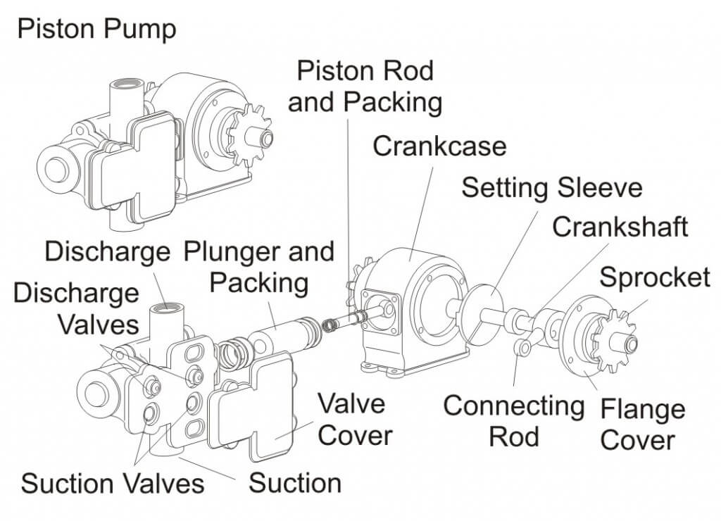
Piston pumps are positive displacement pumps that are favored by many users for their priming ease, higher pressure capability, and constant volume spraying. Piston pumps are often used to apply crop protection products and fertilizers in combination with a ground drive so that flow rate stays proportional to ground speed and application rates remain constant. A pressure relief valve is required, though. Figure 7 is an example of a piston pump used to accurately meter liquid fertilizers.
Figure 7 – Piston Pump
Turbine pumps are also available for low‑pressure sprayers. A turbine pump consists of a rotating turbine within an enclosed housing. These pumps are similar to centrifugal pumps, except they provide higher flow capacity and pressures of up to 70 psi when mounted directly on a 1,000 rpm PTO shaft, eliminating the need for step‑up mechanisms. Because of the close tolerances between the turbine blades and the casing, turbine pumps are better adapted for clean fluids of low viscosity but may have difficulty with wettable powders and suspensions. Figure 8 shows a typical turbine pump.
Figure 8 – Turbine Pump
Gear pumps are positive displacement pumps capable of providing a smooth, low-volume, continuous flow of material. Gear pumps are typically two gears meshing together revolving in opposite directions within a casing. Abrasive materials such as wettable powders rapidly wear the gears and pump housing. Figure 9 shows a typical gear pump.
Figure 9 – Gear Pump
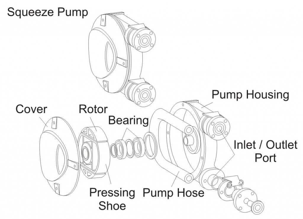
Squeeze pumps are low-pressure, positive displacement pumps with output proportional to speed. Pump flow is created when liquid is trapped by squeezing the hose between a roller and casing. Pump flow is determined by the size and number of hoses. This pump is ideally suited for metering small quantities of fertilizers or pesticides and would be practical for injection-type pumping systems. Figure 10 shows a typical squeeze pump.
Figure 10 – Squeeze Pump
Pump Maintenance
Proper pump maintenance is critical for maximum pump life. Regular cleaning is essential to removing all chemical residues and preventing wear to the pump from corrosive solutions. Do not allow spray solutions to remain in the sprayer for extended periods of time. Using lightweight antifreeze or a motor oil as the final spray solution after cleaning can preserve the pump during a period of non-use.
Pump Selection Worksheet
Acknowledgements
Excerpts for this article were adapted with permission from University of Illinois Circular 1192 developed by Loren Bode and Jack Butler (May 1981), Extension Agricultural Engineer and Professor of Agricultural Engineering, Univerity of Illinois at Urbana-Champaign. Contributions for this article were also received from ACE Pumps Corporation; Hypro Pumps Inc.,; and CDS-John Blue Company.
For more information on pump selection, check out this article.