Category: Pumps and Plumbing

For Basics Category

  • Recirculating Booms – Introduction to the Concept

    Recirculating Booms – Introduction to the Concept

    Listen to the audio version of this article here

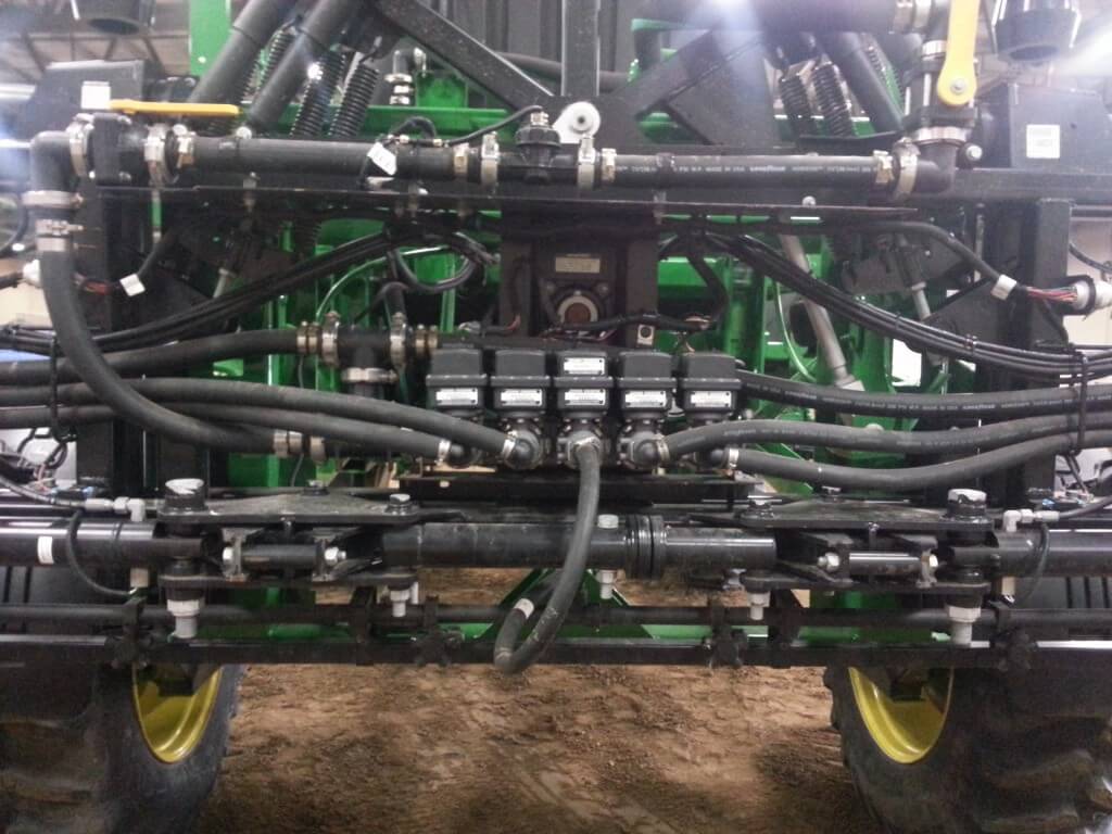
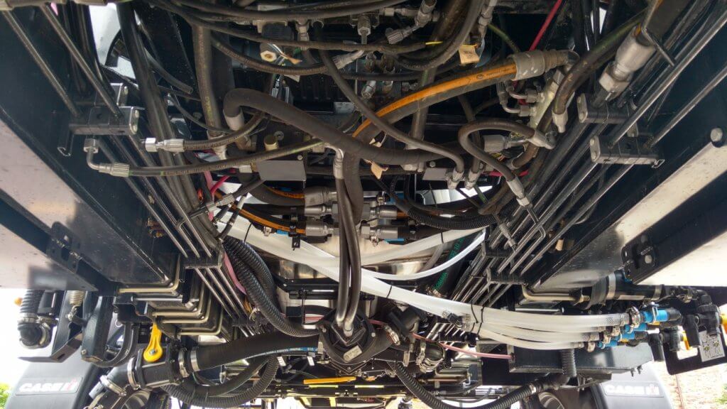
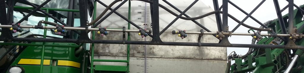
    A lot of people are intimidated by sprayer plumbing. One look at the spaghetti bowl of spray mix and hydraulic hoses and valves, and they walk away. It hasn’t helped that much of it is concealed under the frame and all of it is in the same black colour, so figuring it out on your own is almost impossible.

    Belly of a typical sprayer, showing black hydraulic and spray hoses.

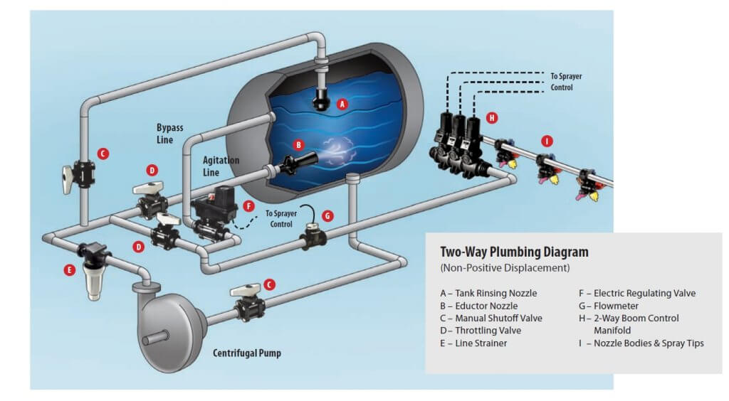
    Let’s quickly review the basics. In all sprayers, the liquid in the tank is drawn out from the bottom and pressurized by a pump. The pressurized liquid is split into two main paths. One goes to the spray boom to hydraulic atomizers (nozzles). The other goes back to the tank to agitate the liquid and act as a pressure bypass when the booms are off. Bypass throttling changes pressure. That’s it.

    Sprayer plumbing diagram (Source: TeeJet).

    By the way, has anyone ever thought of some colour-coding or labelling the hoses and valves on a sprayer? We’d definitely appreciate that.

    Conventional boom sections

    Most North-American sprayers feed the pressurized liquid to the boom, where the flow is subdivided into physical sections that define the various portions of the boom that can spray at any one time. Older sprayers might only have two sections, the left and the right boom. Wide booms now have anywhere from 5 to 13 sections, each about two to four metres wide. Each section has a pressure feed to its middle, and each section terminates at two dead ends, at which we place caps or valves for flushing.

    A conventional plumbed boom with two sections. Each section has two terminal ends that require cleaning. Boom can only be flushed or primed by spraying or by opening boom end caps.

    Sprayer with nine sections, each controlled by its own valve and each running a dedicated feed hose.

    Two partial boom sections, each showing a central feed line and a capped boom end.

    Sectional boom end showing 10 cm of capped pipe beyond last nozzle body.

    Boom end with valve to facilitate draining and flushing.

    Any liquid that enters this type of boom must exit at the nozzle or the boom end. It must be sprayed out or drained. This poses three distinct problems.

    • If the boom contains water or a previous spray mix, the boom needs to be primed with the new product before spraying. We need to spray or drain the existing product out.
    • If we want to clean the boom or flush it with water, again we need to push the existing liquid out.
    • If we have dead spots in the boom section, such as a boom end, we need to take special care to flush those out as well.

    These characteristics complicate cleaning, create waste or contamination, and take time.
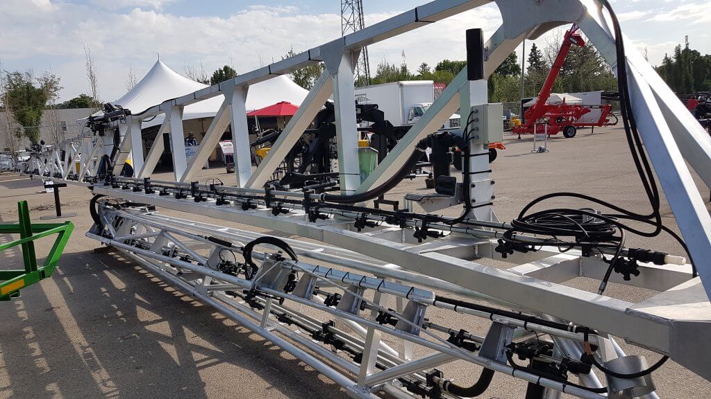
    Recirculating booms

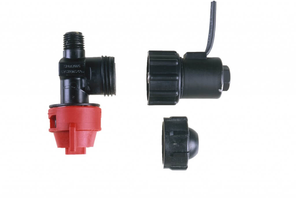
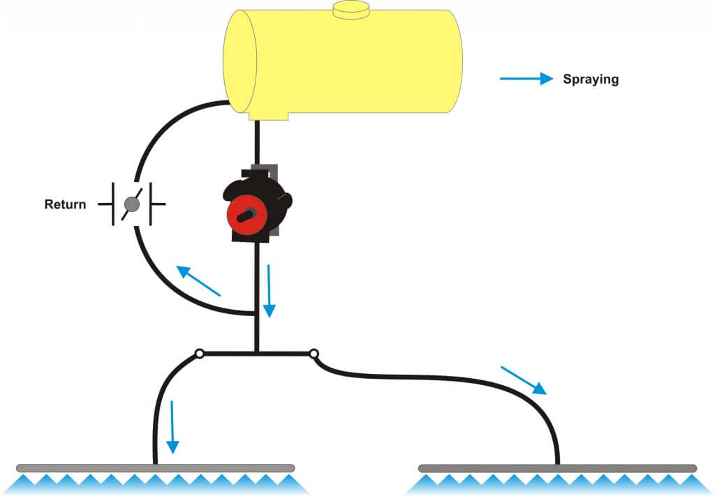
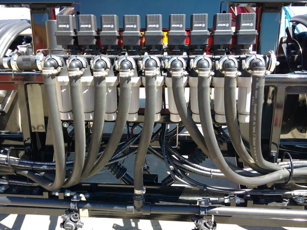
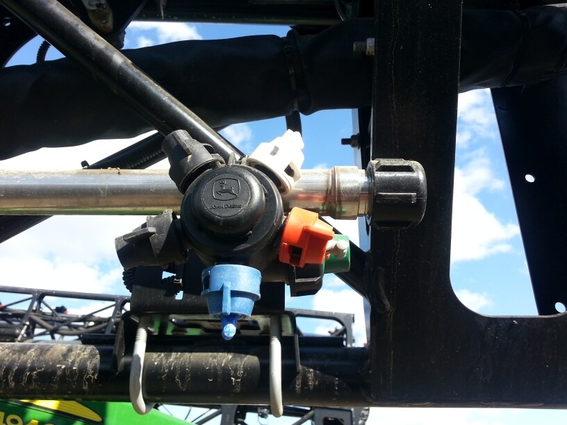
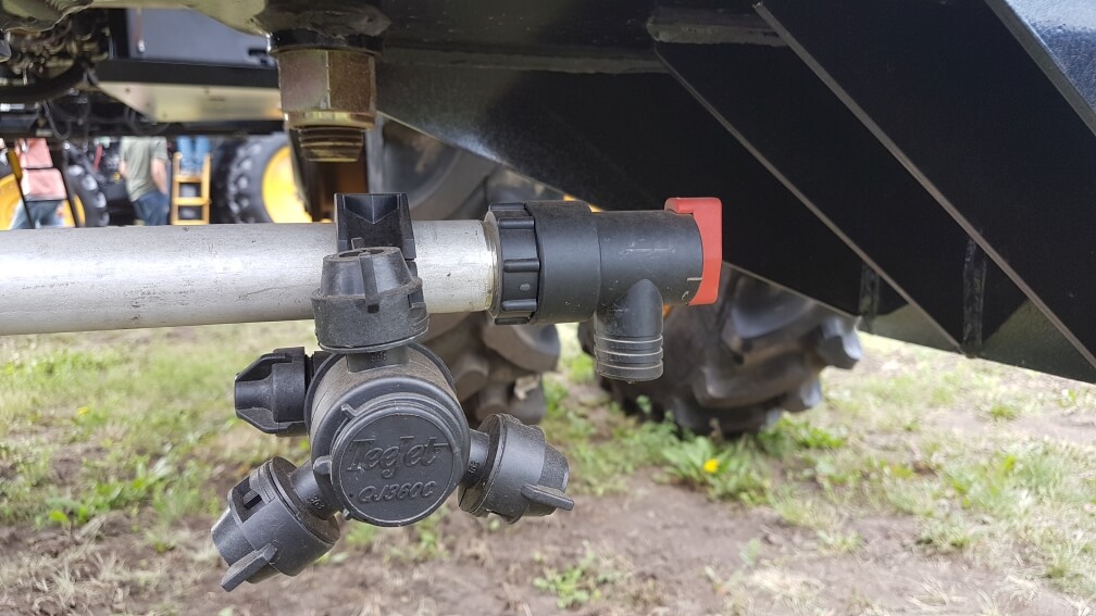
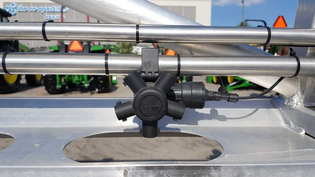
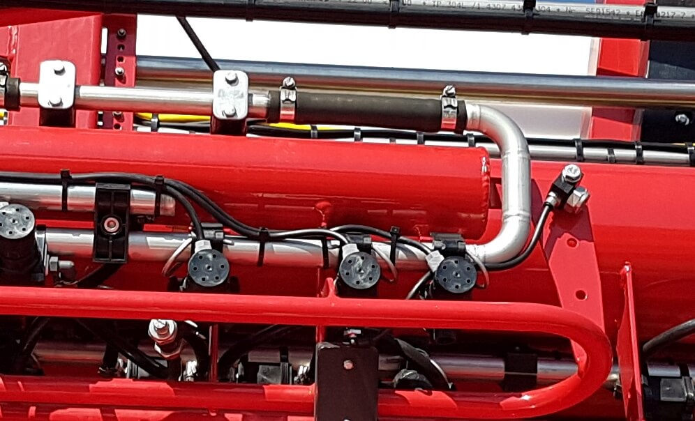
    In a recirculating boom, the spray mixture enters the boom at one end and exits at the other, returning to the spray tank. In most cases, the left and right wing each has its own feed and return. Sectional control is achieved via individual valves (air or electric) placed on the nozzle bodies.

    There are two main types of recirculating booms on the market.

    The first system routes the pressurized mixture into the boom and shuts off the return line during spraying. When the nozzles are shut off for a turn, the return line opens automatically and the boom flow is pushed past the nozzles back to the tank. When the nozzles spray again, the return line closes to pressurize the boom. 

    Recirculating boom system offered by Pommier. One end of boom is pressurized, the other end is return. Return flows when boom spraying is shut off. Boom can be primed or flushed without spraying.

    This is the system used by Pommier, the French aluminum boom manufacturer who first introduced recirculating booms to North America.

    Pommier recirculating boom.

    Pommier boom showing stainless steel supply and return lines, as well as air-activated shutoff valve on nozzle body.

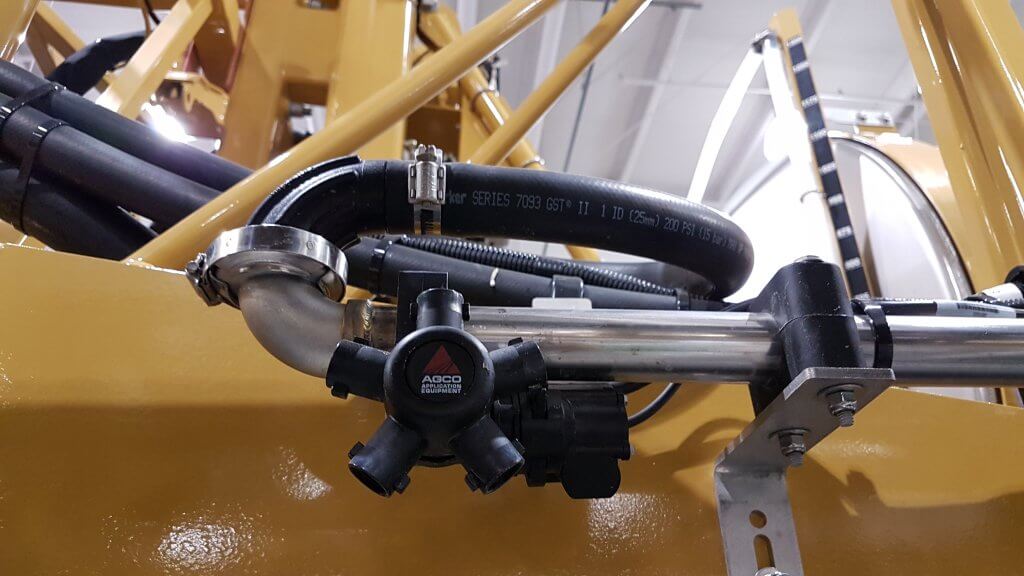
    The second type of system contains a 3-way valve, connected to the return line and the pressure side of the pump. This valve provides the option of either allowing the return line to go back to the tank, as above, or to also allow pumped flow to the return side so that the boom is pressurized at both ends.

    Recirculating boom that allows return line to be either pressurized by pump, or return to tank.

    Top view of D.O.T. Connect sprayer recirculating boom setup. Lower line is pressurized by pump. Upper line is return. Three-way valve allows return line to either go back to tank, or be pressurized by pump.

    Tidy setup of pressure and return lines on D.O.T. Connect system.

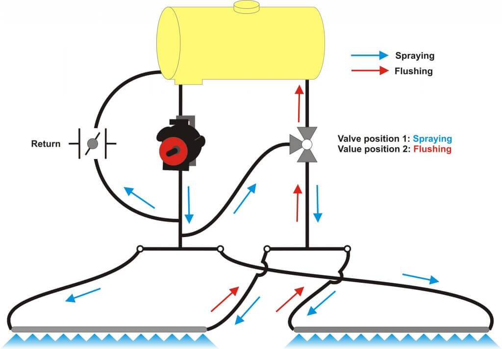
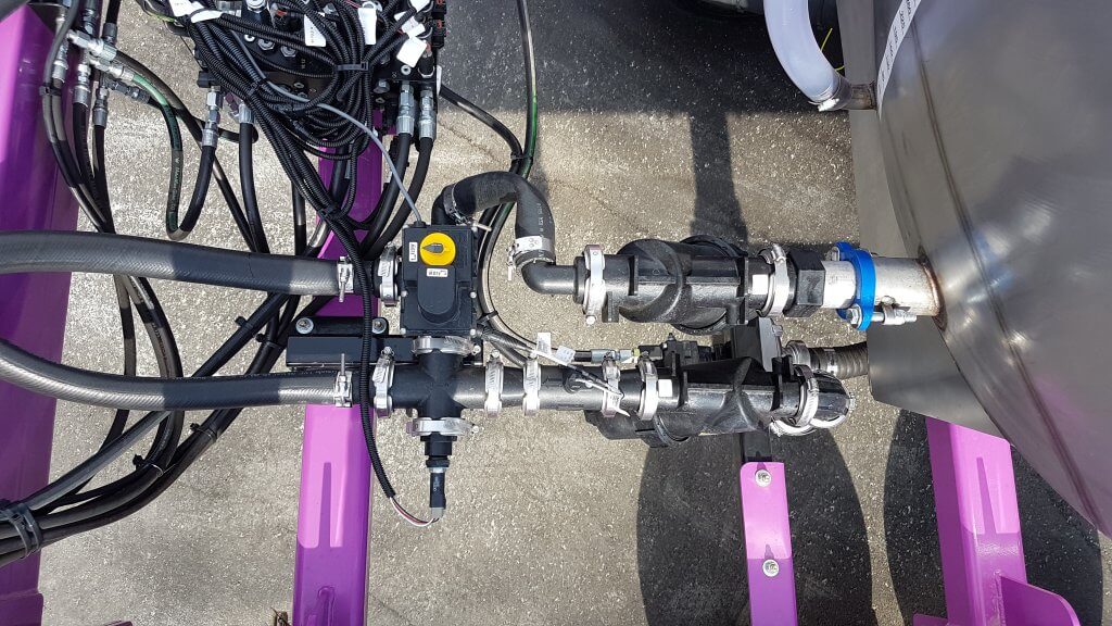
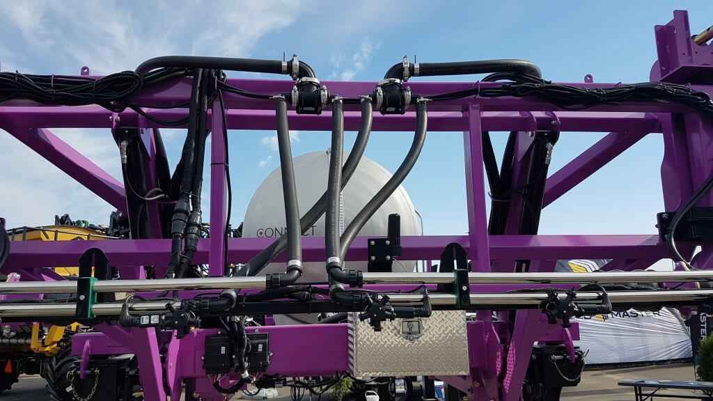
    This feature may be useful with long booms along which pressure drop is more likely to occur, or when very high flows are required, and was introduced to North America by the Dutch manufacturer Agrifac, about which we wrote here and reprinted Mick Robert’s article from Pro Operator here. A similar system is available from Rogator (starting in 2018) via their C-Series featuring LiquidLogic. It has also been used on the Connect sprayer, developed by Pattison Liquid Systems, for the D.O.T. autonomous platform.

    The main advantages of this design are that it provides the option of additional pressure to the spray boom to avoid pressure drop, and to allow any spray mix in the return line to be pushed and sprayed out to the boom for rinsing in the field. This lowers the remaining volume that needs to be diluted.

    Agrifac recirculating boom showing return loop at boom end.

    Boom end on Rogator Liquid Logic system. Note Hypro Pro-Stop E shutoff valve.

    Features

    Recirculating booms offer advantages in terms of preventing soil and water contamination and also in terms of simplifying the boom cleaning process. The design provides an opportunity to graduate to a better resolved sectional control as well due to the requirement for individual nozzle shutoff valves. 

    Due to shorter and less complex lengths of plumbing needed, stainless steel can be used for the return lines which decreases the potential for pesticide residue being adsorbed.

    To rinse a boom with product mix still in the tank, simply draw water from the on-board clean water tank and push it to the boom without activating any nozzle bodies. The mix in the boom is returned to the tank and replaced with water, nothing is sprayed or drained. The tank contents may become slightly diluted depending on the duration of the rinse.

    To rinse the tank as part of the sprayer cleanout, first spray the tank empty. Then introduce clean water into the product tank via the wash-down nozzles and spray that out. As always, either use several batches of  small clean water volumes, or a continuous rinse system, to dilute the remainder most effectively. There may be additional volume to dilute from the return lines compared to a conventional system, depending on the type of recirculating system is used. However, boom ends no longer exist and this saves effort and ensures a more thorough rinsing.

    To prime a boom that contains water, simply open the return lines back to the tank and allow the new mix to flow through the boom. Again, some dilution of the tank will occur due to the water in the boom.

    The value of spray-free rinsing and priming adds up. Each prime, for example, consumes about 30 US gallons before the spray reaches the last nozzle of the longest section. Much of that product ends up on the ground, probably while the sprayer is stationary, and probably in a similar place on the field year after year.

    Since a recirculating boom requires a powered individual nozzle shutoff, this adds some cost. However, the opportunity of improved sectional control via virtual sections is significant (most monitors offer 16 virtual sections that can be configured). Well-configured virtual sections can save several percent from overlaps.

    Recirculating booms remove many of the contamination problems associated with conventional plumbed sections. They save time, money, and reduce environmental impact. We think they should be offered on sprayers.

    Here’s a link to a nice article on recirculating booms written by Spencer Myers for the Manitoba Co-operator. A video that goes with the article can be found here.

  • The Agitation over Agitation

    The Agitation over Agitation

    Sprayers101 recently received a couple of seemingly unrelated questions about airblast sprayers:

    What are the advantages and disadvantages of mechanical versus hydraulic agitation? Why would someone want a stainless tank versus the cheaper poly or fiberglass options?

    Recognizing that each manufacturer has their own reasons for the features and materials used in their sprayers, we posed these questions to Mr. Kim Blagborne (formerly of Slimline Manufacturing). The following article was written from Kim’s response, and it turns out these two questions are very much related. Kim writes:

    This is a great debate among customers and manufacturers, and it’s difficult to stay neutral. Let’s consider the following:

    Hydraulic Agitation

    The flow required for hydraulic agitation requires about 30% of the pumps total capacity. This is very important because many sprayers cannot achieve, or maintain, this minimum requirement whilst spraying. This may be why it’s rare for a sales person to demonstrate agitation while the sprayer is spraying; quite often, the agitation slows or even stops. And, of course, because everyone gets wet.

    Let’s say an airblast sprayer has a pump with a manufacturer-listed capacity of 26 gallons per minute (gpm) (Click to download the spec sheet for the pump). The figure in that output chart is determined on a bench at 540 rpm and at 50 psi. However, when an operator uses that pump in the field, they run it at ~150 psi, and that brings the pump capacity down a bit to 25.5 gpm.

    Now we build in the line pressure drop associated with the sprayer’s plumbing. Effectively, another 8-10% of the pump’s output is lost to plumbing (a figure easily measured by collecting the total output capacity of the pump). Let’s say we are now down to a practical capacity of 23 gpm.

    If the operator’s crops are on 14 foot rows, it would be reasonable to spray 200 gpa at a travel speed of 3 mph at 150 psi. With both booms spraying that’s a required flow of 16.8 gpm.

    Remember, our hypothetical 26 gpm pump can only provide 23 gpm in the field. When we subtract the 16.8 gpm required for spraying, we’re left with 6.3 gpm excess capacity for agitation. But, we said we needed 30% of the pump’s 26 gpm capacity, and that comes out to 7.8 gpm. We’re short by 1.5 gpm, or stated differently, we’re about 20% short of what we need.

    Why don’t we see that deficit? Because the flow to the booms is prioritized, and therefore the sprayer output matches the calibration, so everything seems OK. But no one sees the reduced return flow through the regulator, and certainly no one peeks into the tank while spraying to see that the hydraulic agitation is greatly reduced.

    And so, while everything looked great during loading, the spray mix (especially SC and WDG formulations) may not stay suspended correctly during spraying. In extreme cases, that could lead to burning a crop (high concentration) at the start of a spray job, and reduced efficacy (low concentration) at the end. We’re quick to blame the chemical, but no one ever thinks to question hydraulic agitation.

    Let’s consider it from another angle: TeeJet suggests a model number 62905c-5 jet agitator for a sprayer with a 250 US gallon tank. To correctly agitate the contents of this tank, we will need 30 psi and 7.6 gpm (see the chart below).

    Unfortunately, there is no simple way for an operator to measure the agitation pressure or the flow, so it goes unchecked. The only way to determine if the flow demand is satisfied is to apply the generic rule of 30% of pump capacity and make an estimate. That’s pretty loose math since we’ve already established that the listed capacity may not reflect reality.

    Still another angle: Many operators now employ the Gear Up, Throttle Down (GUTD) approach to match their sprayer air settings to the crop canopy. However, when we reduce PTO input speed we also reduce pump capacity. Remember our piston diaphragm pump with the 26 gpm capacity at 540 rpm? We still need 16.8 gpm to spray, but reducing the rpm’s by 100, per GUTD, drops our pump output to only 23.16 gpm.

    23.16 minus 16.8 equals 6.36, and we needed 7.8 gpm to maintain sufficient hydraulic agitation. Oops.

    Mechanical Agitation and Tank Material

    There are definite advantages to mechanical agitation. It is not affected by the PTO speed because it is already excessive at 540 rpm. This means there is no pump capacity issue and it allows the operator to take advantage of GUTD.

    There are also a few disadvantages. Unlike a hydraulic system, mechanical agitation requires maintenance, such as regular (daily?) greasing. The packing where the the system inserts into the spray tank also requires occasional inspection and adjustment to prevent leaks.

    And of course there’s sticker shock. Many European manufacturers offer hydraulic agitation because it is ~$500.00 CAD less expensive. Further, mechanical agitation creates vibrational stress on tanks walls, which fiberglass or plastic tanks can’t handle for long. The solution is stainless tanks, which is a more expensive material. Further, stainless cannot be moulded around pumps and rotating parts, so more steel is required, adding to expense and weight.

    In my opinion, there is sufficient benefit to stainless to easily recover the investment. Beyond permitting mechanical agitation, there’s durability. We have stainless tanks built in 1948 that are still operating today, and we’ve never found a plastic or fiberglass tank that can claim that. There’s also sprayer sanitation. It has long been know that stainless cleans more easily and more reliably that plastic or fiberglass, especially as the tanks begin to age.

    Closing

    The decision to buy a sprayer with hydraulic agitation or mechanical agitation lies, ultimately, with the consumer. But be sure to look past the price tag, and under the hood. Ensure that you have sufficient agitation to properly suspend your tank mix, and give you the flexibility to Gear Up and Throttle Down to improve your spray coverage and efficacy.

  • Plumbing Projects That Make Spraying Easier and Safer

    Plumbing Projects That Make Spraying Easier and Safer

    Some of our biggest struggles in spraying involve the start and end of each spray day.

    When starting a new field after the sprayer is cleaned, we need to prime the boom. If it’s full of water, that water has to be purged and the question is always for how long and where to do this (pro tip at bottom of article).

    At the end of the day, we should ideally clean the sprayer. During that process, we may struggle with waste disposal, including large rinsate amounts, and course, the uncertainty of whether the job is actually done (since clean water looks exactly the same as contaminated water).

    If not cleaning the entire sprayer plumbing, we should at least rinse the boom, even if we’re returning to the same product the following day. It can prevent future problems.

    These tasks are complicated by the increasingly convoluted plumbing featured on modern sprayers. Ask someone to explain their sprayer’s plumbing system to you one day. It’s a long story! A bright spot is the well-engineered, compact, and accessible Agrifac system.

    Fortunately, virtually any sprayer can be modified to suit your needs. Let’s talk about a few ideas for a winter project:

    1. Boom flush. It’s good practice to flush clean water through your boom at the end of spraying even if the main tank remains full of product. Some sprayers have an air purge system to eliminate liquid from the plumbing and that is a great feature. A water flush should follow that purge so that any residual pesticide is diluted and removed before it can dry on and become hard to remove later.  First you’ll need a clean water tank on the sprayer (150 gal is enough). Second, plumb a feed so that this clean tank can be the sole source of the water supplied to the solution pump. Select this source, shut return lines down or off, and pump clean water through boom.  Sprayers that have an auto-rinse cycle will likely be able to draw clean water, but may not be able to push it to the boom, directing it to the wash-down nozzles instead. Check to see what’s possible, and make the changes you need.
    2. Clean water pump. Installing a second pump dedicated to the clean water tank has several advantages. We’ve talked about continuous rinsing before, here, and here, as a way to dilute the tank remainder faster. It requires installation of a second pump dedicated to clean water. Additionally, give this pump the option to deliver water to the boom, not just the wash-down nozzles. Now it can be used to rinse water through the boom. The main challenge is to obtain a pump capacity that can match the needs of the boom and/or the wash-down nozzles.
    3. Boom ends. We’ve mentioned this part of the boom many times. Boom ends must be flushed regularly to get rid of product and possibly debris that gets stuck there. A simple way to achieve this is to use the Express Nozzle Body End Caps from Hypro. These bleed air continuously, and also prevent accumulation of dead-end contamination. They do need to be flushed, and this can be done by pulling a plug or rotating the turret to an open (no nozzle ) position.
    1. Recirculating boom. This is a significant change, but worth considering. Conventional plumbed booms are separated into five to 13 sections. Each has two ends at which the spray stops and where air and contamination can accumulate (see point #3). Each section feed has a shutoff valve.  Once the spray mixture leaves the pump and bypass valve, it is committed to leaving the sprayer.  In a recirculating boom, the boom becomes a part of the tank and the liquid can return to the tank if desired. Spray is pressurized at one or both ends, and valve positions determine its flow. Sectional control is achieved with individual nozzle shutoff, air or electric.
      1. Three advantages:
        (a) the boom can be primed with new product without spraying. The surplus goes back to the tank.
        (b) the boom can be flushed with water without spraying while material is still in tank, and without spilling anything on the ground. Again, the surplus goes back to the tank.
        (c)  high resolution sectional control with individual nozzle shutoff is a byproduct of this design. Fast response, high res, saves money.
    2. Steel lines. Steel cleans easier than plastic, and this material makes a lot of sense for booms. But it also makes sense for the boom feeds, currently handled by black rubber hose.  This hose is a literal black box. We can’t see inside it, and we don’t know if and where potential contamination resides. It has considerable surface area. Consider replacing portions of your feed lines with steel. The boom is the obvious candidate. Aside from easier cleanout, it also helps with faster nozzle shutoff because it doesn’t expand with pressure.

    A word about dumping the tank on the ground. It’s a bad practice for many reasons. Let’s examine just one of those. When you spray a product at 10 gpa, you actually cover each square meter with about 10 mL, or 1/3 oz, of spray mix. When you flush your boom ends on the ground, you’re probably dropping 2 or 3 gallons in the same area. That’s 1000 times the label rate at each boom end, 10 to 26 times per boom. If you dump your tank remainder and all the hoses, say 20 or 30 gallons, that’s 10,000 times the label rate if it covers 1 sq meter. That’s leaching, runoff, residual potential, and not a good story.

    Many of the changes we outlined above help prevent that from being necessary.

    Pro Tip: To find out how much water your plumbing (from the pump to the boom ends) holds, do this: After cleaning with water and before spraying an EC formulation (white milky appearance in tank, some crop oils are ECs) reset your sprayed gallons on your rate controller. Start spraying and watch for the last nozzle on your furthest and longest section to spray white. Stop spraying and check your sprayed gallons. That’s your volume. No matter the size of nozzle or application volume, it stays constant. To be sure the boom is primed with a new mix, spray until those gallons are reached and you’re set.

  • The Pressure Gauge Shows More Than Pressure

    The Pressure Gauge Shows More Than Pressure

    Kim Blagborne (formally with Slimline Manufacturing) has long said that the pressure gauge on an airblast sprayer indicates more than just pressure. It can be used to diagnose a number of pump and plumbing issues… if you know what to look for. Here’s Kim’s troubleshooting guide to reading into what your gauge is REALLY telling you:

    Scenario One

    “As the tank empties, the pressure drops”

    First, try adjusting the pressure regulator (assuming a positive displacement pump). If you can maintain the pressure up until the tank empties, your intake line may be loose and it’s sucking the bottom of the tank. Check the fitting between the suction filter and the pump. Apply a light coating of grease to the O-rings on the elbows and filter to ensure a complete seal.

    Second, try stopping mid-tank (that is, turn off the tractor PTO and let the sprayer sit for a few minutes). Does the pressure gauge return to the original set pressure? If so, then the intake line inside sprayer has likely come loose entirely. Open the lid, and using a straightened-out coat hanger, hook the intake line and give a few gentle tugs – it should not be able to move. If it does, you’ll have to re-fasten the intake line so it’s not sucking the bottom of the tank.

    The humble coat hanger. It opens our cars and now fixes our sprayers. Remarkable!
    The humble coat hanger. It opens our cars and now fixes our sprayers. Remarkable!

    Scenario Two

    “When I first start the sprayer, the pressure drops or fails to maintain constant pressure as the tank empties”

    This might indicate improper mixing practices because the filter is probably plugging with product. Alternately, your PTO speed may be too slow to drive sufficient mechanical agitation. Check the suction filter as soon as the problem occurs (don’t finish spraying). If you wait to check when the tank is empty, the evidence of a plugged filter could be washed away before you can confirm it. This problem often happens when spraying nutrients, or when products aren’t compatible.

    If that’s not it, it could be a collapsed suction valve. The pump will sound like it’s “missing” (like an misfiring engine). The suction valve might need to be replaced.

    Or, perhaps you notice that you can compensate for the pressure drop by adjusting the regulator on the first tank. But it has to be dropped back down again for the second tank. In this case, the regulator might be sticking or jamming. Disassemble it and look for grit in the barrel of the regulator, then lubricate the parts.

    Scenario Three

    “I lose pressure when I turn my boom(s) on or off”

    In this scenario, the pressure is fine as you approach the end of the row. You turn off the outside boom (or both) and finish the turn. But, when you re-engage both booms, the pressure drops. Even when you adjust the pressure regulator to compensate (assuming a positive displacement pump), the unit only gains the lost pressure slowly. In this case, the regulator might be sticking or jamming. Disassemble it and look for grit in the barrel of the regulator, then lubricate the parts.

    Scenario Four

    “The pressure gauge spikes when I turn off the boom(s)”

    If you run a Turbomist, it could be the bypass balance. To solve this issue, head over to this article and pan down to see the step-by-step. If it isn’t the balance, then it’s likely the regulator. The issue of a spiking gauge and how to correct for it is covered thoroughly in this article by Ag mechanic extraordinaire Murray Thiessen.

    Scenario Five (a positive displacement pump issue)

    “My gauge pulses”

    Is it more than a 20 psi range? Have you noticed that the deviation gets less as the PTO speed increases? Well, the pump pressure check-valve may have collapsed. Check the pressure check valves in the pump for broken springs on the suction valve plate.

    Does the needle move rapidly through a 5 to 10 psi range? The accumulator pressure might be low. Try adjusting system pressure via the regulator and if that changes how the needle is responding, then set an air compressor to 90 psi (or manufacturer’s recommended pressure) and charge the accumulator.

    Perhaps the needle movement is not affected by system pressure changes or the PTO speed. In this case the accumulator may have failed entirely and the diaphragm will need replacement.

    Scenario Six

    “My calibration is going farther than expected”

    Sure, that sounds pretty good at first, but it may be that the gauge is stuck. With the PTO off and the spray boom on, the gauge must read “ZERO”. If it doesn’t, pony up the $50.00 and get a new one.

  • Measuring Pressure Drop

    Measuring Pressure Drop

    All sprayers experience a drop in pressure as the solution moves further away from the pump.  Here’s why that’s important, and how to measure it.

    Optimal nozzle operation in terms of spray quality and fan angle is closely tied to spray pressure.  As we try to maximize travel speed range with a modern sprayer, we often push spray pressure to its limits on the low and high side. For many air-induced nozzles, spray quality and fan angle become critical at about 30 psi.  We need to be sure about the exact nozzle spray pressure to prevent problems.

    Pressure drop is caused by the friction that the spray solution experiences as it moves from the pump to the spray nozzles.  It’s caused by a number of factors, including length of tubing, elbows, valves, screens, and other flow obstructions.

    Plumbing components add friction to liquid flow. If the pressure gauge is installed before these components, the nozzle pressure is unknown but will be lower than the gauge reading.

    The pressure transducer that reports pressure to the cab is usually located between the pump and the manifold that divides the spray into the various boom sections.  At this point, the spray liquid hasn’t experienced any significant flow restrictions.  The transducer basically reports pump pressure.

    Once the spray mixture starts moving through boom sections towards the nozzles, it encounters those restrictions, and pressure at the nozzle will therefore be lower than the cab reading indicates.  The higher the liquid flow, the greater the friction, and therefore, pressure loss.

    Even older sprayers with only two boom sections (left and right) and few elbows and reducers, will see pressure losses due to the narrow and long boom pipe that feeds up to 60′ on each side.

    The nozzle pressure can be measured with a gauge placed on a nozzle body.  Simply purchase a quality gauge and a threaded nozzle cap, combine the two and install in place of a nozzle.

    A pressure gauge threaded into a nozzle cap can measure boom pressure.

    Operate the sprayer at your expected spray pressure (say, 60 psi) with all boom sections on.  Install the portable pressure gauge on an open turret position and turn into place, noting its reading.  If both gauges are accurate, the boom pressure will likely be below 60 psi.

    The difference between the cab gauge pressure and the boom gauge pressure two is the pressure drop.  Repeat the measurement for each boom section.  Also repeat at your lowest, as well as your highest expected flow rates.  Higher flow rates cause greater pressure drops.

    Now, use this information to adjust your interpretation of the cab pressure reading.  For example, if you want to spray at 60 psi and your pressure drop is 10 psi, then the cab pressure should read 70 psi.

    If your boom pressure is higher than your cab pressure, and you’ve checked the accuracy of your new boom gauge, then don’t be too mystified.  Your pressure transducer is malfunctioning.

    This exercise is important if you’re trying to compare your nozzle flow to the expected nominal flow of the nozzle – perhaps you’re trying to determine nozzle wear.  The nominal flow of agricultural nozzles is determined at 40 psi, so it will be important to measure the flow at exactly that pressure.

    By measuring pressure drop on all your boom sections, you also get a good sense of the variability in pressure across your boom.  Your measurements might reveal an obstruction or a hose kink somewhere along the line.

    To see how low pressures can affect coverage, watch this video.

    Note that the pulse-width modulated systems offered by Capstan, Case, and Raven use a solenoid at each valve.  This solenoid adds a known, and significant, pressure drop to the spray system as can be seen here.

    Pulse-Width-Modulation (PWM) solenoids typically have internal flow restrictions that can contribute to pressure drop.

    Here’s a fun video filmed by the Ontario Pest Education Program during a break at Ontario’s Southwest Crop Diagnostic Days: