PWM is gaining popularity, and there is an ever-increasing number of first-time users that need to make nozzle selections for their system. We’ve written about it here, here, and here.
Recall the PWM replaces spray pressure with Duty Cycle (DC) of a pulsing solenoid as the primary means of controlling nozzle flow. The solenoid shuts off the flow to the nozzle intermittently, between 10 and 100 times per second depending on the system. The Duty Cycle is defined as the proportion of time that the solenoid is open, and for low-frequency systems, DC is more or less linearly related to flow rate.
The first rule of PWM nozzle selection is to understand that under average travel speeds, we’d like to see the duty cycle of the system at between 60 and 80%. This means that the nozzle solenoid is open about 2/3 of the time. This value also describes the flow rate as a proportion of the full capacity that nozzle.
The reason for this 2/3 duty cycle rule is to enable four key features of PWM:
It’s ideal for turn compensation, allowing the outer nozzles to increase their flow 20 to 40%, and the inner nozzles to decrease flow about three-fold, in accordance with boom speed.
It allows speed flexibility, providing some additional speed, but more importantly, reduced speeds should conditions require it, without a change in spray pressure.
It compensates for pressure changes so that spray quality can be adjusted without requiring a speed change. Less pressure reduces nozzle flow, and increasing DC recoups accordingly.
It allows for customized higher flows of certain nozzles, perhaps behind wheels, to address reduced deposition in their aerodynamic wake (available on some PWM systems).
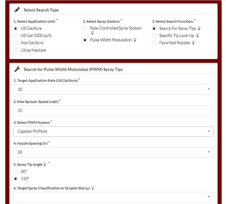
The best tool for selecting the right nozzle size is Wilger’s Tip Wizard. This site asks for your desired average speed ( although it calls this “Max Sprayer Speed”), and reports the expected DC for a host of nozzle size solutions and pressures. It also reports maximum and minimum travel speeds and other useful information such as spray quality.
Fig 1: The Tip Wizard is a useful tool for sizing nozzles on any PWM system. Sizing information applies to any nozzle. Spray quality information is for Wilger ComboJet nozzles only.
Although intended for Wilger nozzles, the site’s sizing feature works for any nozzle brand. It asks the user which PWM system they have for the purpose of calculating the documented pressure drop across the solenoid.
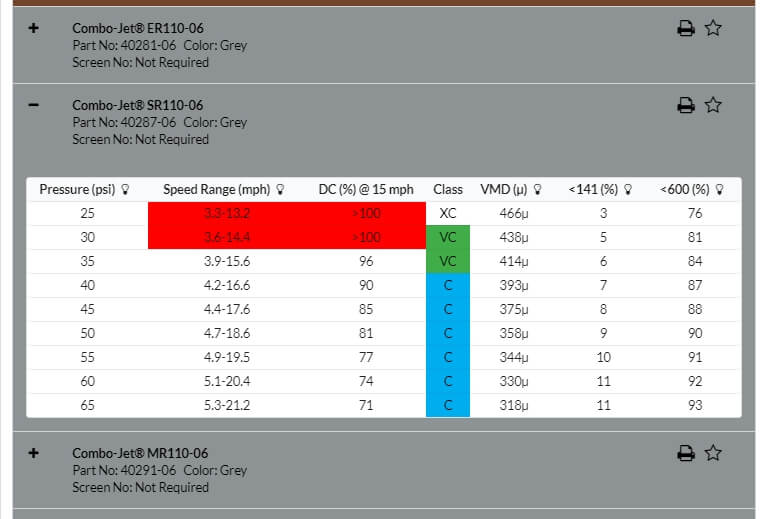
Fig 2: Tip Wizard results for the Wilger SR11006 tip at 10 gpa and 15 mph. Look for a solution that provides 60 to 80% Duty Cycle (DC).
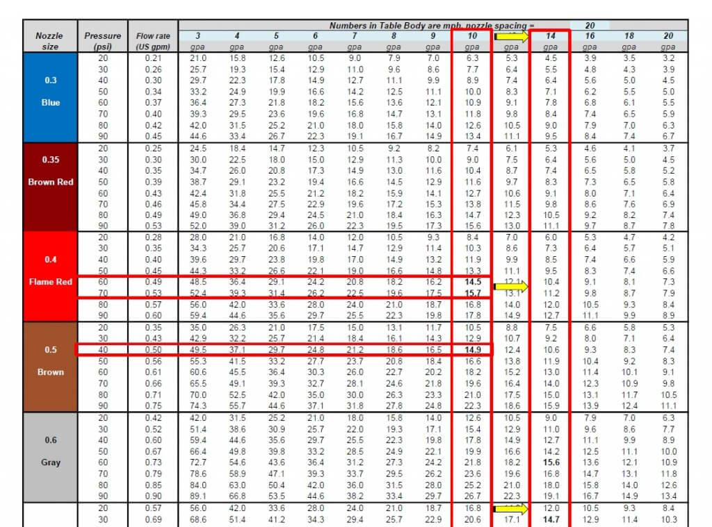
If you don’t have access to the site, a basic calibration chart can still work with a simple trick. Recall that we use the top row to identify the desired water volume, and the table’s interior values are speeds, as described here.
Below are two solutions for someone wanting to apply 10 gpa at 15 mph without PWM. The correct choice depends on the required pressure to produce the needed spray quality.
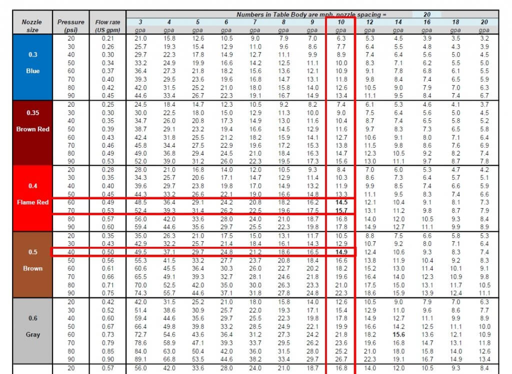
Fig 3: A conventional calibration chart, solving a 10 gpa application for 15 mph.
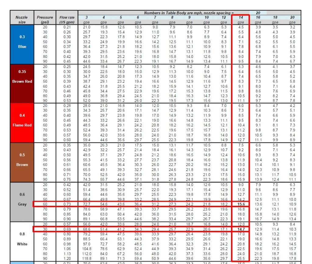
If you want to apply the same 10 US gpa using PWM, simply solve for a larger volume that offers the right DC. For example, choosing 13 gpa will over-apply by 3 gpa, or 30%. The PWM system adjusts by running at 100-30=70% DC. If the chart doesn’t offer 13 gpa, go nearby, to 14 gpa, as we did below:
Fig 4: By pretending to require 14 gpa instead of the actual 10 gpa, the conventional calibration chart is tricked into solving for a nozzle size that will work with PWM at 60% Duty Cycle.
Now solve for the same target speed, 15 mph. The solution will run at 60% DC. Again, there is more than one choice, and that will depend on the spray pressure needed.
Fig 5: Two possible solutions for achieving 10 gpa at 10 mph. An 06 nozzle at intermediate pressure or an 08 nozzle at low pressure.
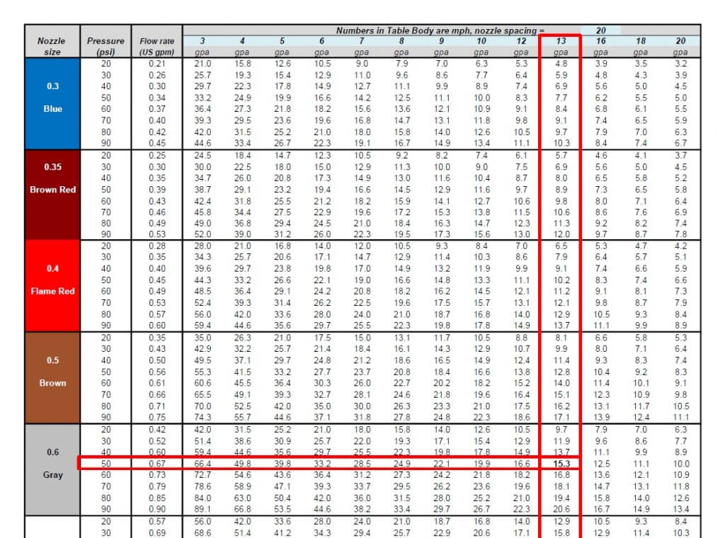
We’ve developed a template, in US or metric units, that can be customized for any water volume. Here is the same chart with 13 gpa added:
Fig 6: A conventional calibration chart with the 13 mph speed added.
The best solution for 10 gpa at 15 mph is the 06 size nozzle at 50 psi. This is not engraved in stone. One of the nice things about PWM is that it has inherent flexibility. Make the nozzle pressure a priority to get the correct spray quality. It really doesn’t matter whether the resulting DC is 65 or 80%, the system will still work well. Simply avoid extremes that take you below 50% or above 90%, they will limit the system’s capabilities.
It can handle any water volume or nozzle spacing by filling in the blue cells. Two additional worksheets in the file automate the process, simply enter the desired application volume, travel speed, and nozzle spacing (yellow cells), and the solution that offers the optimal duty cycle range will be highlighted in light green.
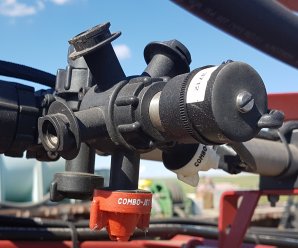
When we consult a nozzle catalogue we are interested in the flow and droplet sizes produced at a given pressure. Perhaps we should also consider the effect of pressure on spray angle. We have several articles discussing the collective impact of spray overlap, nozzle spacing and boom height on coverage uniformity (Check here and here for example). However, we don’t really address the fact that fan angle is not a constant. This may be more relevant with the growing adoption of spot sprayers.
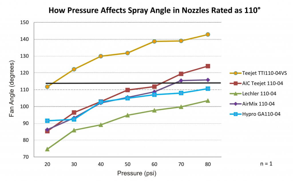
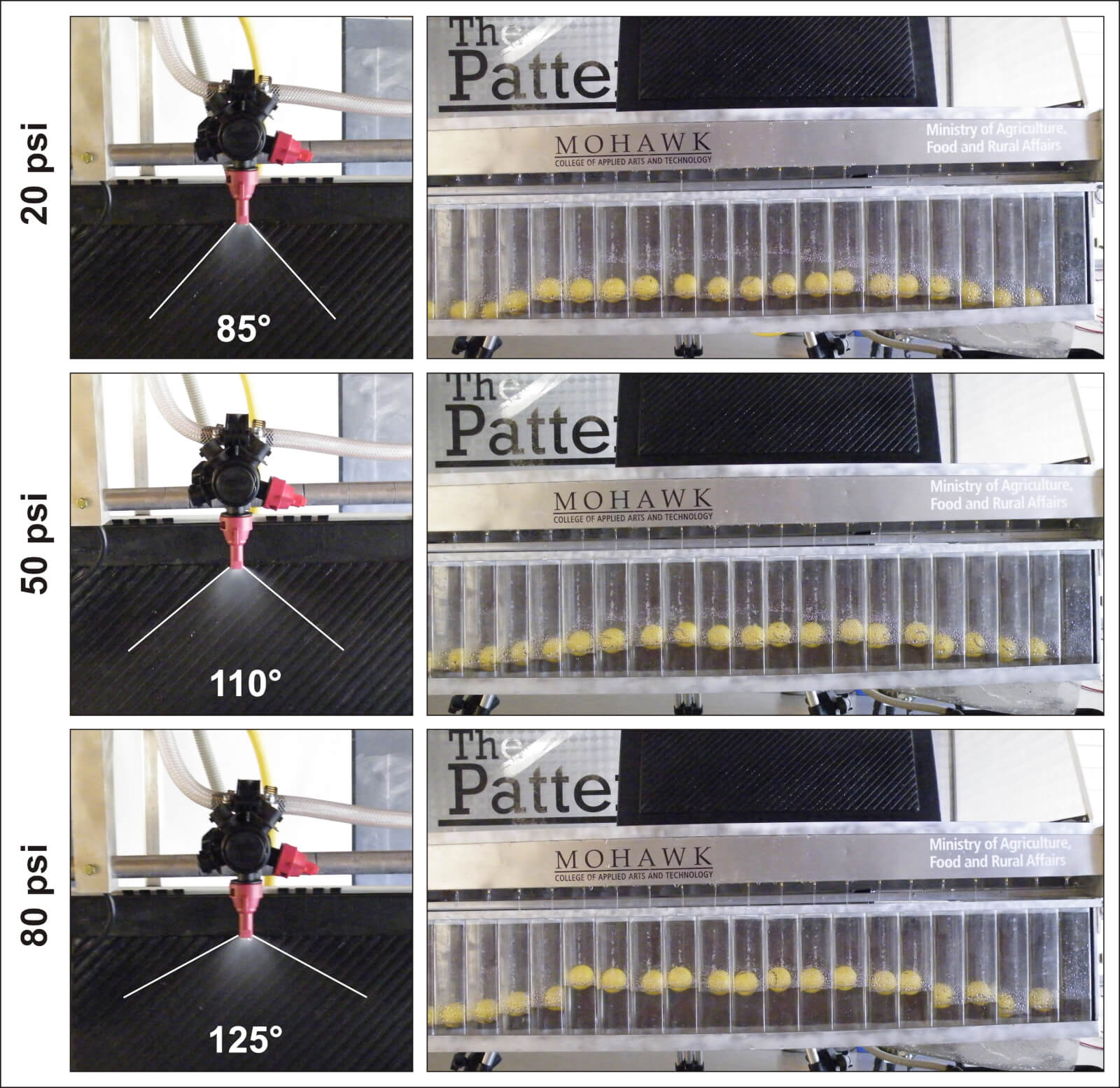
To illustrate the potential for fan angle variation, we assembled a collection of red, flat fan nozzles (‘04s) from several manufacturers. We plugged each nozzle into a spray pattern table, set the regulator at a given pressure, and photographed the spray angle and flow distribution. This process was repeated for each nozzle at seven different pressures within the manufacturer’s approved range of 20-80 psi. After digitizing the photos, we measured the spray angle using a digital protractor.
We anticipated a concomitant increase in spray angle as the pressure increased. This is not news. Anyone who has operated a sprayer has seen the spray pattern open up as the boom fills and pressurizes. Bear in mind this was only performed once (i.e. n=1), so while it illustrates trends it shouldn’t be mistaken for a rigorous scientific comparison. Further, this demonstrates a static situation and not a dynamic one where travel speed, wind conditions and the vortices from the sprayer it self will influence matters.
We saw similar trends with nozzles other than 110˚ fans, but let’s focus on 110˚s due to their current popularity.
Fan angles for five common 110 degree AI flat fans over their manufacturer-recommended pressure range
The spray angle for 110˚ nozzles ranged from 75˚ at 20 psi to approximately 143˚ at 80 psi. One nozzle failed to reach 110˚ at any pressure. Conversely, there was another that was over 110˚ at nearly all pressures. Ideally, spray nozzles should be operated around the middle of their manufacturer-recommended operating range. Three of the nozzles tested came close to 110˚ at that median pressure, but only the TeeJet AIC110-04 measured 110˚ at the middle of its recommended range (~50 psi).
Using that nozzle as an example, let’s look at the pressure, spray angle and subsequent distribution of flow along the swath at three different pressures. At 20 psi, the spray angle was 85˚. The yellow balls are floats that reflect flow as a series of cross sections of the swath. We see that aside from the tapered edges (which illustrate the need for 100% overlap between neighbouring nozzles) the distribution was fairly even. One of the priorities in nozzle design is to ensure a low coefficient of variability over the operating pressure range. In other words, the length of the swath may change, but the spray quality and uniformity in that swath is still within spec. At 50 psi the nozzle produced the expected 110˚ fan, and the spray distribution remained even. At 80 psi, the angle spread out to 125˚, spanning a greater distance, but it started to produce a less-even distribution.
Photographs of spray angle and distribution for the TeeJet AIC110-04 at the extreme low, middle and highest pressures of its recommended pressure range.
When fan angle changes with pressure, it can have significant implications. Nozzle spacing on a boom varies from sprayer to sprayer. Generally 50 cm (20 inch) centres are the standard in North America, but we’ve seen 15″ and even 10″. Nozzle spacing and boom height collectively determine the degree of spray overlap. Excessive overlap isn’t a problem, although additional nozzles do mean added expense, cleaning time and potential for plugging. Conversely, gaps in the pattern could lead to sub-lethal applications or flat-out misses. For example, in this soybean demo plot (below) we sprayed a contact herbicide at low pressure to collapse the spray pattern. You can see the alternating stripes of hits and misses that resulted from an incomplete overlap of spray.
Soybean demo plot sprayed with a contact herbicide using 110˚ air induction flat fans at 20 psi. The collapsed spray pattern did not overlap sufficiently to burn the entire crop down, leaving a striped pattern and demonstrating the poor coverage.
Nozzle manufacturers generally recommend a 100% spray overlap for flat fans. This creates sufficient overlap when the boom sways low to the ground. It also increases the degree of droplet size homogeneity under the boom as coarser and fewer droplets are generally found at the “horns” or edges of the pattern compared to the centre. In order to ensure this degree of overlap, sprayer operators should observe and consider changes in fan angle over their typical pressure range. Otherwise, the cost of poor deposit uniformity under the boom could be high.
Operate nozzles around the middle of the manufacturer-recommended pressure range. However, just because a nozzle is rated over a range of pressures does not mean the angle is constant.
Lower pressures are a greater concern than higher pressures. 30 psi is the absolute lowest pressure for operating a 110˚ air induction flat fan; the ideal operating range for these nozzles is 50-70 psi.
If nozzles are not maintaining the recommended 100% overlap at your preferred pressure range, then consider switching nozzle rates, and adjusting pressure and boom height.
This work was performed with Victoria Radaukas, 2015 OMAFRA application technology summer student.
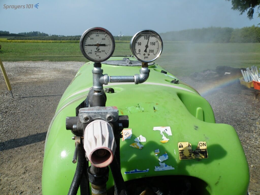
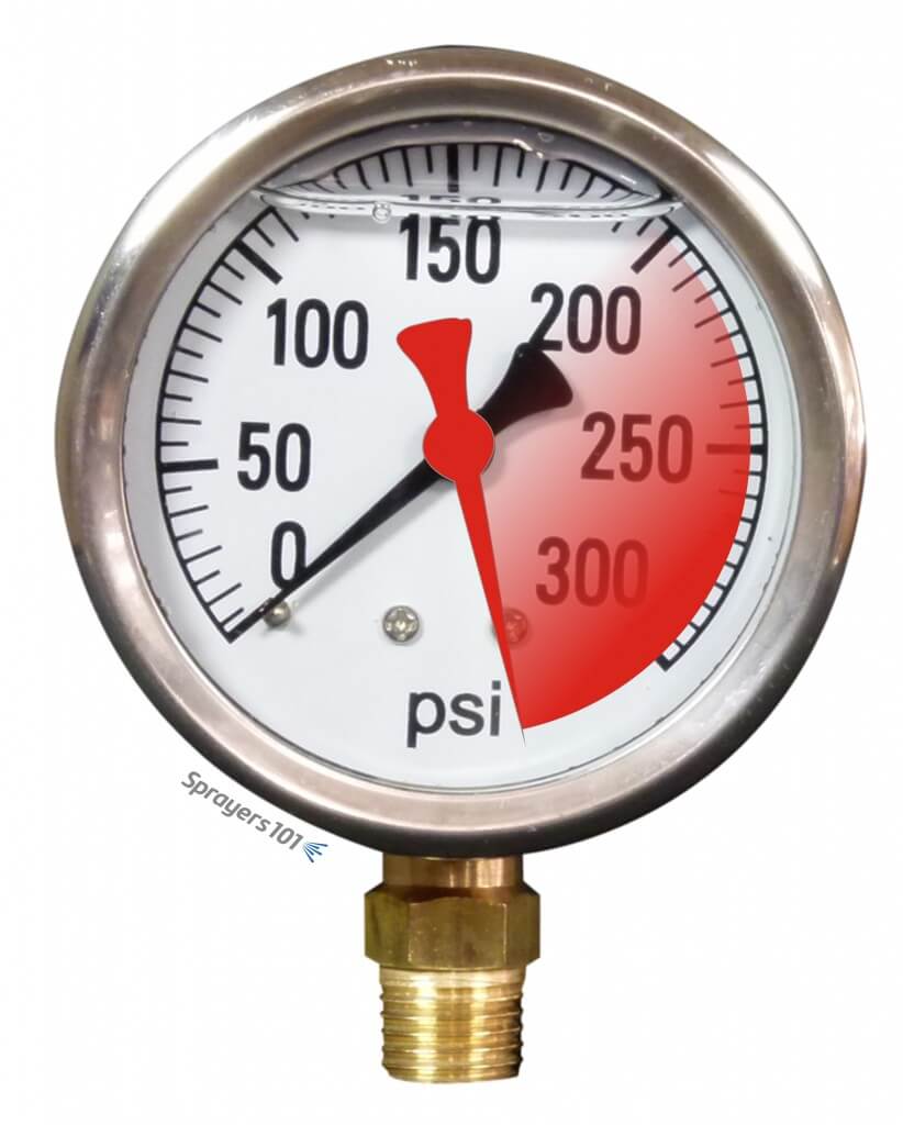
The role of pressure is often underappreciated in spraying. Many airblast operators (still) don’t use rate controllers, so the only way to monitor sprayer pressure is using a single liquid-filled pressure gauge located near the pump… and it may not be trustworthy. An inaccurate pressure gauge may cause you to spray more or less product than you intended. That translates to wasted resources and potentially higher residue levels. Conversely, spraying less than intended may lead to reduced efficacy and the need to re-apply. Many operators use budget pressure gauges on their sprayers and have never tested or replaced them.
Testing pressure gauges
Here are a few clear indications that your pressure gauge should be retired:
Gauge has an opaque or unreadable face
Mineral oil leaking or mostly gone
Needle does not rest on zero pin when sprayer is not under pressure (it has likely spiked)
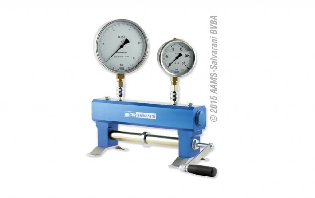
Sometimes a gauge is not obviously in need of replacement. To test it, you need to apply a known pressure to see if it is reading accurately. One way to do this is using a commercial manometer.
AAMS-SALVARANI manometer
These systems work well, but they can be an expensive proposition if you only use them once in a while. In a past sprayer workshop, one participant had a great suggestion for testing gauges. His idea was to use an air compressor (which most farms have) and some simple plumbing to create a homemade manometer. Be sure to vent the gauges before testing.
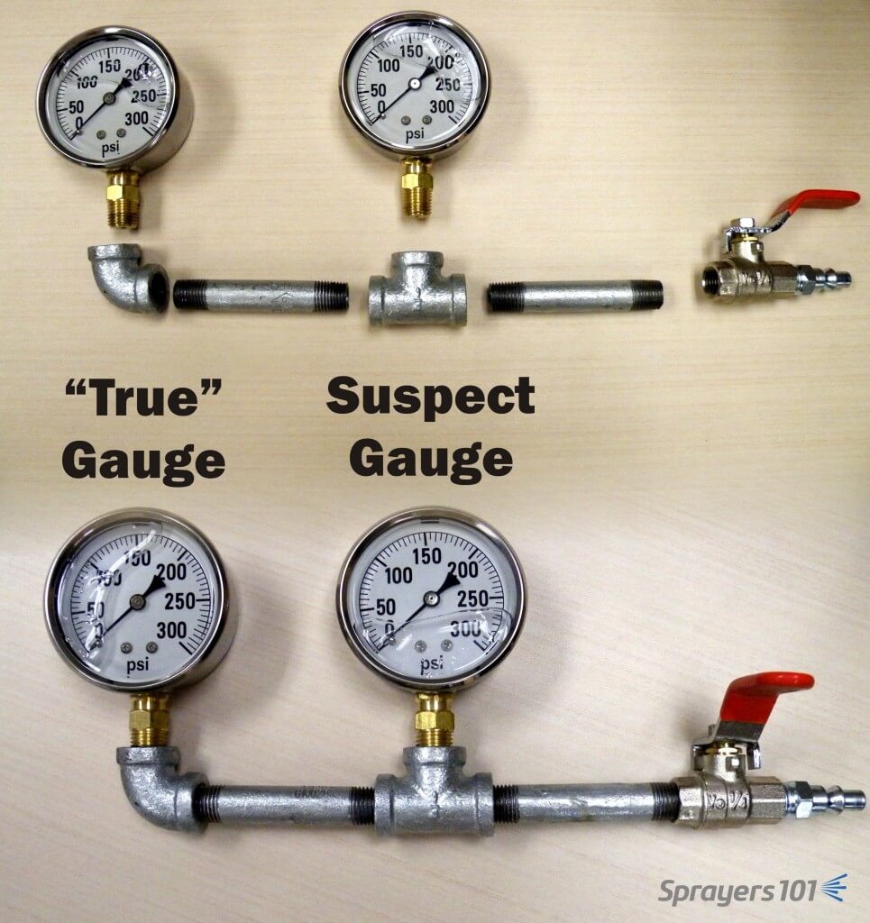
The “Pressure Gauge Tester”. The accurate gauge is in the elbow and is compared to the suspect gauge in the tee. Concept: K. Voege, Ontario.
This tool allows you to test your suspect gauge (set in the tee) against an accurate gauge (set in the elbow) for less than $75.00 CAD. Construct your own “Pressure Gauge Tester” using the following parts (valve optional):
Part
Approx. Price (CAD)
¼” by 3” Galvanized nipples (x 2)
$3.50
¼” Galvanized 90º elbow
$3.50
¼” Galvanized Tee
$3.50
¼” Ball valve (threaded)
$10.00
*Plug Air Connector (A over ¼”)
$4.00
Teflon pipe tape
$3.00
†300 psi liquid-filled gauge
$40.00
*Depending on the quick-connect fitting on your compressor
†The range of the accurate gauge should match your existing gauge. The range of your existing gauge should be twice as much as your typical operating pressure.
As a public service announcement, be aware that many budget, liquid-filled gauges are inaccurate right off the shelf. A 5% variance is typical. When replacing a worn gauge, or buying the “accurate” test gauge for your homemade manometer, buy a few and save the receipt. Test them in different combinations to ensure they all agree with one another. Return the extras and let the dealer know if you discover an inaccurate gauge. I’m sure they won’t put it back on the shelf for the next person… *ahem*.
Gauges should be rated twice as high as your average operating pressure. For example, if you typically spray at 150 psi, your should have a gauge rated up to 300 psi. That way, you can see small changes in pressure more clearly. Plus, if your needle is pointing straight up, a quick glance confirms the ideal operating pressure.
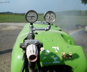
Another way to confirm pressure gauge accuracy is to install a second in-line. They’ll keep one another honest. This may be difficult if the gauge set into a molded plastic tank, or located under the chassis next to the pump where it is not visible from the tractor.
Two gauges keep each other honest – this GB (Italian-made Good Boy) is sporting a home-made assembly that cost ~$75 CAD to assemble. The silver spray paint on the black pipe prevents rust and makes it look pretty darn sharp. Note that they should be the same range, but are not in this photo. The one on the right is the correct range for this operating pressure.
Measuring and Correcting for Pressure Drop
Boom pressure can sometimes be less than the desired operating pressure (a phenomenon known as “pressure drop”) and must be accounted for. Pressure drop is affected by hose diameter, hose fittings, and the distance from the pump. You’ll find it at the far ends of boom sections on field sprayers and it’s an issue that plagues many low-pressure, tower-style sprayers. Dress appropriately because you’re going to get wet performing this diagnostic.
Fill a clean sprayer about half-full with water.
Install a liquid-filled test gauge in the highest nozzle position of one of the booms. The image below shows how the nozzle cap or entire nozzle body may need to be removed for this step. For Metric fittings, contact your sprayer dealer – they can be hard to find.
With the tractor parked, bring up the rpms and get the lines to the desired operating pressure.
Open the boom(s) and measure the pressure at the nozzle farthest from the pump. All nozzles on all booms should be open during this test. That’s why you are wearing PPE.
For positive displacement pumps, adjust the main pressure regulator until the test gauge reads the desired pressure. For centrifugal pumps, it is possible to make small changes to the pressure, but more important to note any pressure differential for later considerations regarding nozzle output and spray quality.
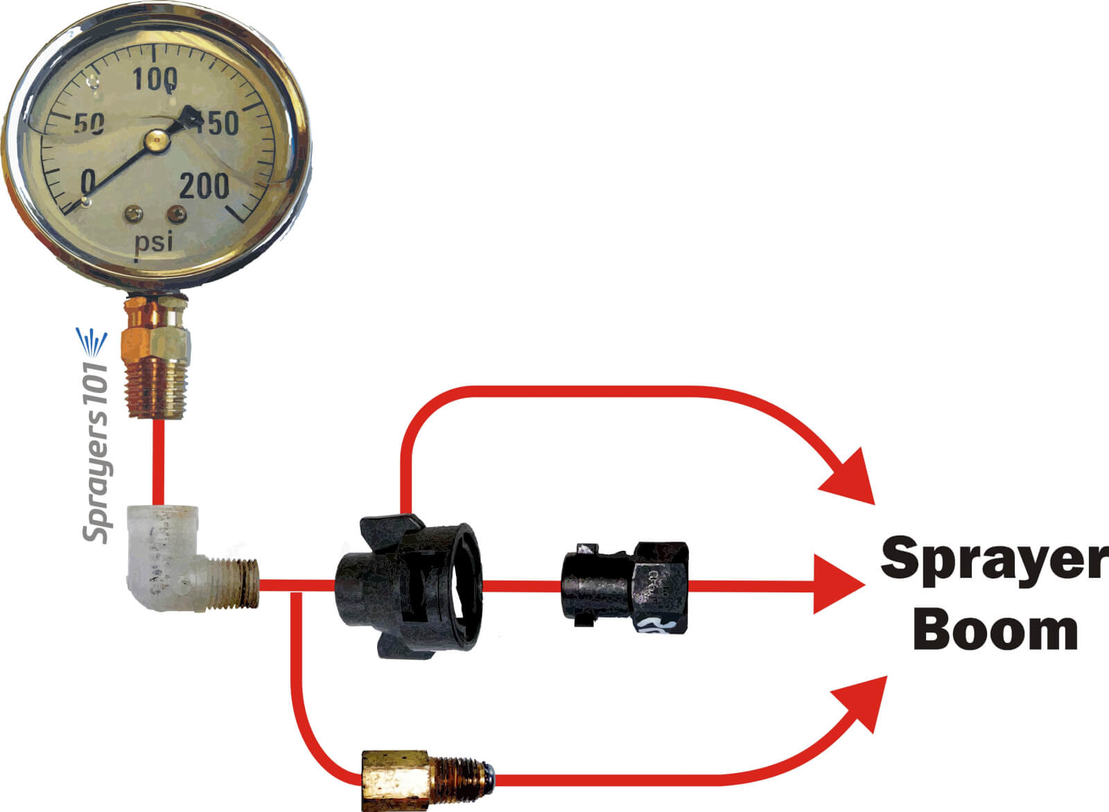
There are many ways to install a gauge onto a nozzle body. Here are three examples of common fittings.
Switching between multi and single boom operation
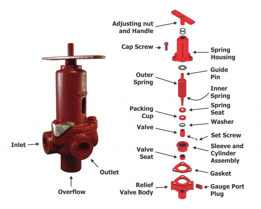
When sprayers that employ a positive-displacement pump are switched to one-sided operation (E.g., border spraying or during turns), the pressure can change considerably. Most units will experience a pressure increase, thereby increasing the boom output. This is typically an indication of a faulty relief valve, which is positioned between the pump and nozzles. It’s actuated by a spring-loaded piston or diaphragm, opening and closing in response to changes in pressure. The operator sets the desired pressure and any additional pressure forces the valve open, diverting excess flow back to the tank via a bypass.
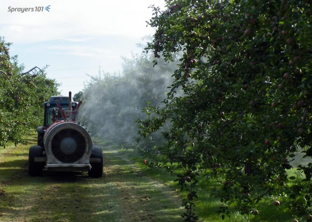
Spraying from one boom. This operator checked to make sure the pressure didn’t increase when he closed the second boom. High pressures or sudden spikes could indicate a faulty relief valve.
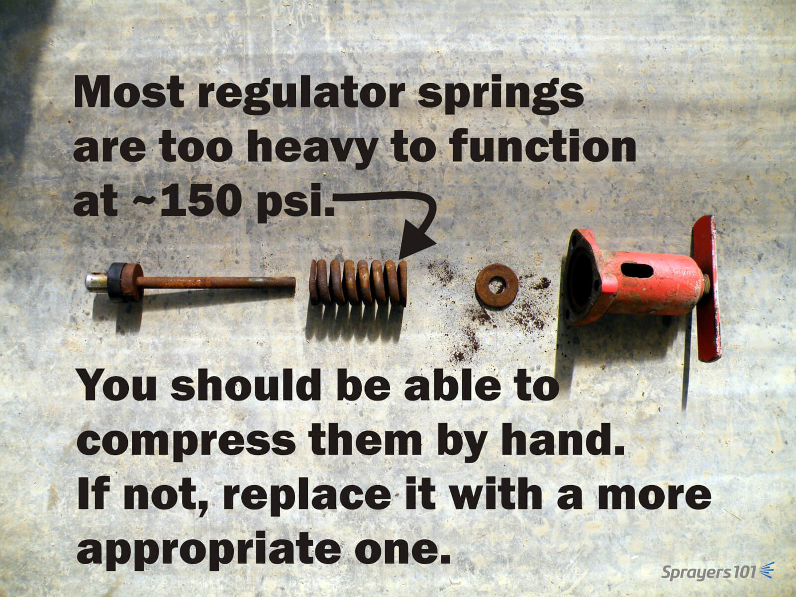
This problem can be greatly reduced by properly sizing the regulator (specifically the spring) to the typical operating pressure. Many sprayers come equipped with regulator springs matched to the maximum pressure range of the pump (often 600 – 900 psi). These springs are unable to respond to changes when operating at lower pressures (E.g., 100-200 psi, which is typical of applications to moderately-sized canopies).
The springs are so stiff that the liquid pressure is unable to act on the spring and the valve essentially acts as a flow control (throttling) valve rather than a pressure control valve. Liquid pressure is difficult to control using a throttling valve; it is unable to compensate if the tractor engine speed drops while driving uphill and sprayer output is subsequently reduced. Further, this phenomenon can cause pressure gauges to spike.
Valve springs and seats wear out, such as in this regulator assembly. Check yours each season. If you spray using moderate pressures, be sure your regulator spring can compensate for small changes.
Some sprayer designs attempt to compensate for excess flow during single-boom operation. They employ an additional throttling valve to shunt the volume that would normally would be spraying out through the closed boom. The result is that the pressure should remain constant when a single boom is shut off. If your sprayer has this feature, here’s how you set the valve:
With PTO at application speed and both booms open, adjust regulator to calibrated operating pressure.
Close one boom.
If pressure increases, open throttling valve to achieve calibrated operating pressure. If pressure decreases, close throttling valve to achieve calibrated operating pressure.
Repeat process for the other boom, and find a compromise position for the valve.
Some operators elect to remove the handle from the throttling valve once it is set so they don’t accidentally bump it later. That’s fine, but further adjustments may be required when transitioning between dilute and concentrated volumes, so don’t lose the handle.
Here’s an oldie-but-a-goodie filmed in New Hampshire in June, 2014. It’s something to keep in mind when you’re getting your sprayer ready for spring service. Thanks to Chazzbo Media and Penn State Extension for making an unscripted and spur-of-the-moment concept into a polished video.
A properly-sized pump should produce more flow than is needed and work in conjunction with the atomizers to regulate that flow. Typical to high pressure pumps, a piston relief valve (aka regulator) should maintain the desired system pressure through the normal speed range of the sprayer, regardless of the number of booms (or boom-sections) that are on or off. This is achieved by balancing the sprayer pressure against the relief valve spring, which must move freely across a range of flows.
But what does it mean when the pressure gauge briefly spikes off-scale when boom are turned on or off? This is bad for the gauge and will eventually cause it to fail. Quite often, pressure spikes are an indication of one of two things:
A dirty or stuck valve
An inappropriate spring size
A pressure gauge spiking beyond its range.
Relief valve maintenance
Sometimes, pressure spikes indicate a need for valve cleaning and maintenance.
The regulator spring cavity may be packed with dirt, which limits valve travel. Clean the housing and spring, and then lubricate and adjust.
The regulator may be partially seized or sticky. If the regulator piston and cylinder bores are caked with spray they will ‘hold’ the valve until the pressure/spring balance overcomes the friction.
Sometimes valve, and/or the valve guide pin are seized. Disassemble them, clean all sliding surfaces, then lubricate and adjust.
Valve/seat wear may have created a leak. You may have already tightened the spring to compensate, but this loads the spring past the pressure balance point you want to spray at. This means that when the booms are shut off, the pressure increases until it reaches the ‘new’ spring balance point. Repair (or replace) the regulator, then lubricate and adjust. Be aware that any leak (external or internal) can contribute to this condition and tightening the spring isn’t the solution.
The spring may be damaged (e.g. bent, corroded, etc.). Replace the spring, lubricate and adjust.
Note: Be sure to read the operator’s manual before you do anything. You should understand your sprayer’s design before you perform any maintenance, adjustments or calibration.
Spring size
Sometimes, the relief valve may be mechanically sound, but the spring may not be sized to match a reduced operating pressure. Relief valve springs match the maximum pressure range of the pump. Sprayers operated at lower pressure may be unable to compress the spring. This is common when people switch from disc-core nozzles operated at higher pressure to molded nozzles operated at lower pressure.
This would manifest when one boom is shut off for single-boom operation; there may not be enough pressure to open the bypass. As a result, flow increases over the remaining boom.
Recognizing this problem, some operators have teed-in a second relief valve capable of finer adjustments at lower pressures. Make sure you know what you’re doing if you’re considering this option.
Technically, a spring can either be too weak, or too heavy:
The spring may be too weak for the pressure being used (i.e. any adjustment bottoms out). In order to obtain sufficient pressure the operator tightens the spring until it is virtually collapsed, essentially creating a fixed orifice. When the booms are closed the ‘fixed orifice’ doesn’t compensate and pressure rises to force the increased flow through that small orifice.
If the spring is too heavy for the pressure being used (any adjustment barely touches the spring when pump is turned off). In this case, the pressure being used will not deflect the spring, so the operator closes the regulator until the ‘fixed orifice’ creates sufficient restriction to flow to achieve the desired pressure. When the booms are closed the ‘fixed orifice’ doesn’t compensate and pressure rises to force the increased flow through, or until the spring begins to deflect.
In either situation the spring must be sized so it is in the centre-third of its flex range (i.e. rest state > fully collapsed) at the desired pressure. You can buy springs from the sprayer dealer or hardware supply. Try to maintain original length and diameter of the coil, while varying the diameter of the wire.
Engineering
In some cases, it is not a matter of valve maintenance, or spring size, but poor engineering. Consider the following:
The valve supply and return may be too small for the pump flow. Consult hose and fitting catalogs for flow capacities and lengths. Re-size the hoses and fittings appropriately, and then adjust the regulator.
There may be kinks or sharp bends in in the supply and return lines. Re-route the hoses and/or fittings to avoid kinks and sharp bends, and then adjust the regulator.
The relief valve may be too small for the pump flow. Consult a regulator catalog for flow capacities and replace the regulator with an appropriate size. Calibrate the regulator spring and adjust.
Relief valves have a ‘cracking’ pressure (that’s when the valve just starts to open). Well-designed regulators have small pressure changes from ‘cracking’ to full flow. That information is in their catalogs. Poorly designed regulators have large pressure changes between these two ratings and these regulators should be avoided.
The pump may be too big for system. This often happens when sprayers are upgraded and pumps are replaced. Consult the catalogs and reduce pump size or speed, or increase the sizes of the hoses, fittings and regulator.
There may be a hydraulic agitator jet on the regulator ‘tank’ line. An agitator jet applies considerable back pressure to a system, and when booms are closed the increased flow causes more than a linear increase in pressure.
Broadly, the sprayer system as a whole may be poorly engineered. Inspect and draw a flow path of the sprayer system. Examine where everything is going (or not going). Is it possible someone made changes that the manufacturer did not intend? Consult the manufacturer if you are uncertain. Sometimes, it will have to be re-engineered, which may require expert consultation.
Note: Your pressure gauge can tell you a lot more than your operating pressure – it can indicate a problem with your regulator, pump, lines or overall sprayer engineering. Don’t ignore it – address it.
Thanks to Murray Thiessen, Consulting Agricultural Mechanic, for his contribution to this article.
Us this handy visual guide to identify a mystery nozzle you may find on a field sprayer. We’ve included the most common low-drift nozzles found on North American, European, and Australian sprayers. The list does not contain any conventional flat fan nozzles.
It’s in alphabetical order by manufacturer.
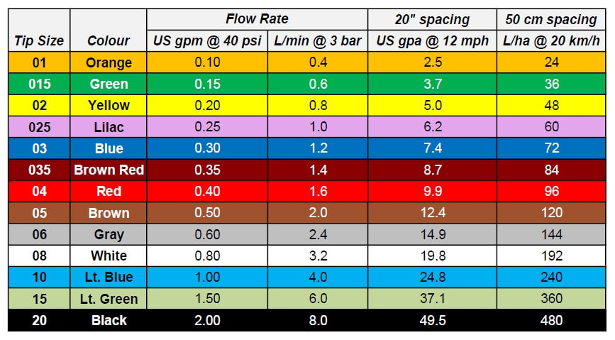
First, a reminder of the ISO colour coding of nozzles by nominal flow rate, and their approximate output at normal speeds and nozzle spacings.
ISO Flow rate colour coding and benchmark application volumes for US and metric units
Also recall that most nozzles have markings that identify their fan angle (usually 30, 40, 65, 80, 90, 110, 120, 130, or 150 degrees, with 80 and 110 being most common) or flow rate (in US gpm, as shown in figure above).
Albuz(manufactured in France)
Albuz AVI (also John Deere ULAC) Type: Air-Induced Average Pressure: 60 psi Average Spray quality: VC Sizes Available: 01 – 10
Albuz AVI Twin Type: Air-Induced Twin Average Pressure: 60 psi Average Spray quality: VC Sizes Available: 01 – 06
Arag (manufactured in Italy)
Arag Compact Fan Air (CFA) Type: Air-Induced Average Pressure: 60 psi Average Spray quality: C Sizes Available: 01 – 04
Arag Compact Fan Air Ultra (CFA-U) Type: Air-Induced Average Pressure: 60 psi Average Spray quality: C-VC (intended for 2,4-D label compliance in Australia, available in 01 – 03 sizes only)
Arag Twin Fan Low Drift (TFLD) Type: Pre-Orifice, suitable for PWM Average Pressure: 60 psi Average Spray Quality: VC – XC Sizes Available: 02 – 05
Billericay Farm Systems (manufactured in UK)
Billericay Farm Systems Air Bubble Jet (ABJ) Type: Air-Induced Average Pressure: 60 psi Average Spray Quality: M-C Sizes Available: 01 – 06
Billericay Farm Systems EasyJet (known as Pulzar in UK) Type: Pre-Orifice, suitable for PWM Average Pressure: 60 psi Average Spray Quality: M-C Sizes Available: 01 – 08
Greenleaf / Agrotop (manufactured in Germany)
Greenleaf AirMix (made by Agrotop) Type: Air-Induced Average Pressure: 60 psi Average Spray Quality: C Sizes Available: 01 – 06
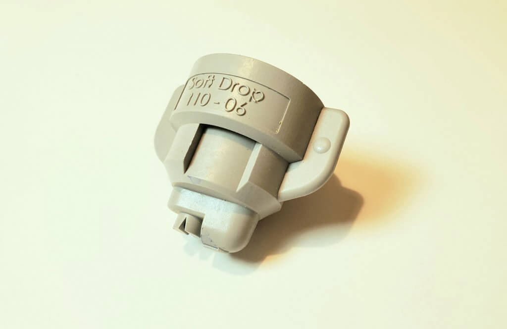
Greenleaf SoftDrop (made by Agrotop) Type: Pre-orifice, suitable for PWM Average Pressure: 60 psi Average Spray Quality: XC – UC Sizes Available: 04 – 10
Greenleaf TurboDrop-XL (TDXL, made by Agrotop). TDXL-D appears same, but has larger exit size and produces coarser sprays for dicamba Type: Air-Induced Average Pressure: 60 psi Average Spray Quality: TDXL, C-VC, TDXL-D, XC-UC Sizes Available: 01 – 15 (08 for -D)
Greenleaf TADF (made by Agrotop). TADF-D appears same, but has larger exit size and produces coarser sprays for dicamba Type: Air-Induced Asymmetric Twin Average Pressure: 60 psi Average Spray Quality: TADF, C-VC, TADF-D, XC-UC Sizes Available: 01 – 15
Greenleaf Dual Fan (DF, made by Agrotop), asymmetric twin. Similar to Hypro TwinCap, assembly can house two nozzles to produce a twin spray.
Greenleaf Low Drift Dual Fan for PWM (BPDF) Uses AirMix nozzles with air portion removed. Spray Quality M – XC Sizes Available: 06 – 12
Hypro Pentair / John Deere (manufactured in UK and USA)
Hypro Guardian (Also John Deere LDX) Type: Pre-orifice, suitable for PWM Average Pressure: 40 psi Average Spray Quality: M Sizes Available: 015 – 08
Hypro GuardianAIR (GA, also John Deere Low-Drift Air, LDA) Type: Air-Induced Average Pressure: 60 psi Average Spray Quality: C Sizes Available: 015 – 05
Hypro Ultra Low-Drift (ULD, also John Deere ULD) Type: Air-Induced Average Pressure: 60 psi Average Spray Quality: C – VC Sizes Available: 015 – 08
Hypro Ultra Low-Drift Max (ULDM) Type: Air-Induced, approved for PWM by Hypro Average Pressure: 60 psi Average Spray Quality: UC Sizes Available: 04 – 08
Hypro GuardianAIR Twin (GAT, also John Deere GAT) Type: Air-Induced Twin Average Pressure: 60 psi Average Spray Quality: M-C Sizes Available: 02 – 08
Hypro 3D (also John Deere 3D) Type: Pre-Orifice, suitable for PWM Average Pressure: 40 psi Average Spray Quality: M Sizes Available: 015 – 08
Hypro TwinCap. Assembly can house two nozzles to produce a twin spray.
John Deere LDM Type: Pre-Orifice, suitable for PWM Average Pressure: 60 psi Average Spray Quality: C – VC Sizes Available: 03 – 10
John Deere LDM showing characteristic twin pre-orifice
Lechler (manufactured in Germany)
Lechler ID Type: Air-Induced Average Pressure: 60 psi Average Spray Quality: C – VC Sizes Available: 01 – 10
Lechler ID3 Type: Air-Induced Average Pressure: 60 psi Average Spray Quality: C – VC Sizes Available: 01 – 10
Lechler IDTA Type: Air-Induced Asymmetric Twin Average Pressure: 60 psi Average Spray Quality: C Sizes Available: 02 – 08
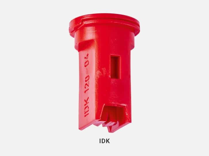
Lechler IDK (Also Hardi MiniDrift) Type: Air-Induced Average Pressure: 60 psi Average Spray Quality: C Sizes Available: 01 – 10
Lechler IDKT (Also Hardi MiniDrift Duo) Type: Air-Induced Twin Average Pressure: 60 psi Average Spray Quality: C Sizes Available: 015 – 06
MagnoJet (manufactured in Brazil)
Magnojet MUG Approved by EPA for Dicamba in US Type: Air-Induced Average Pressure: 70 psi Average Spray Quality: UC Sizes Available: 015 – 05
TeeJet (manufactured in USA)
TeeJet AIXR Type: Air-Induced Average Pressure: 60 psi Average Spray Quality: C Sizes Available: 015 – 10
TeeJet AI Type: Air-Induced Average Pressure: 60 psi Average Spray Quality: VC Sizes Available: 015 – 15
TeeJet TurboTeeJet (TT) Type: Pre-orifice, suitable for PWM Average Pressure: 40 psi Average Spray Quality: M-C Sizes Available: 01 – 12
TeeJet TurboTwinJet (TTJ60) Type: Pre-orifice Twin, suitable for PWM Average Pressure: 40 psi Average Spray Quality: M-C Sizes Available: 02 – 10
TeeJet Air-Induced TurboTwinJet (AITTJ60) Type: Air-Induced Twin (approved for PWM by TeeJet) Average Pressure: 60 psi Average Spray Quality: C-VC Sizes Available: 02 – 15
TeeJet TurboTeeJet Induction (TTI) Type: Air-Induced (approved for PWM by TeeJet) Average Pressure: 60 psi Average Spray Quality: XC-UC Sizes Available: 015 – 15
TeeJet Twin TurboTeeJet Induction (TTI60) Type: Air-Induced Twin (approved for PWM by TeeJet) Average Pressure: 60 psi Average Spray Quality: XC-UC Sizes Available: 02 – 08
TeeJet AI3070 Type: Air-Induced Twin Average Pressure: 60 psi Average Spray Quality: C-VC Sizes Available: 015 – 05
TeeJet AccuPulse TwinJet (APTJ) Type: Pre-orifice Twin, suitable for PWM Average Pressure: 60 psi Average Spray Quality: XC- UC Sizes Available: 015 – 08
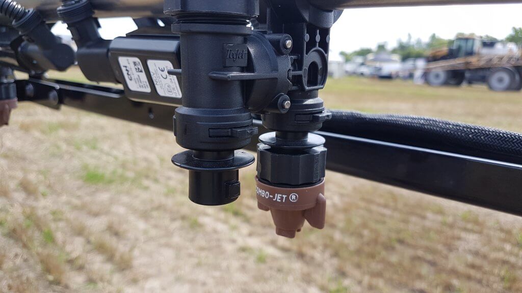
Wilger ComboJet (manufactured in US and Canada)
Wilger ComboJet Available as ER,SR, MR, DR, and UR models. Appear similar, requires inscription to differentiate Type: Pre-orifice, suitable for PWM Average Pressure: 50 psi Average Spray Quality: ER: M SR: C MR: VC DR: XC UR: UC Sizes Available: 01 – 25