Tag: chart

  • How to Size a Nozzle for Pulse Width Modulation (PWM)

    How to Size a Nozzle for Pulse Width Modulation (PWM)

    PWM is gaining popularity, and there is an ever-increasing number of first-time users that need to make nozzle selections for their system. We’ve written about it here, here, and here.

    Recall the PWM replaces spray pressure with Duty Cycle (DC) of a pulsing solenoid as the primary means of controlling nozzle flow. The solenoid shuts off the flow to the nozzle intermittently, between 10 and 100 times per second depending on the system. The Duty Cycle is defined as the proportion of time that the solenoid is open, and for low-frequency systems, DC is more or less linearly related to flow rate.

    The first rule of PWM nozzle selection is to understand that under average travel speeds, we’d like to see the duty cycle of the system at between 60 and 80%. This means that the nozzle solenoid is open about 2/3 of the time. This value also describes the flow rate as a proportion of the full capacity that nozzle.

    The reason for this 2/3 duty cycle rule is to enable four key features of PWM:

    1. It’s ideal for turn compensation, allowing the outer nozzles to increase their flow 20 to 40%, and the inner nozzles to decrease flow about three-fold, in accordance with boom speed.
    2. It allows speed flexibility, providing some additional speed, but more importantly, reduced speeds should conditions require it, without a change in spray pressure.
    3. It compensates for pressure changes so that spray quality can be adjusted without requiring a speed change. Less pressure reduces nozzle flow, and increasing DC recoups accordingly.
    4. It allows for customized higher flows of certain nozzles, perhaps behind wheels, to address reduced deposition in their aerodynamic wake (available on some PWM systems).

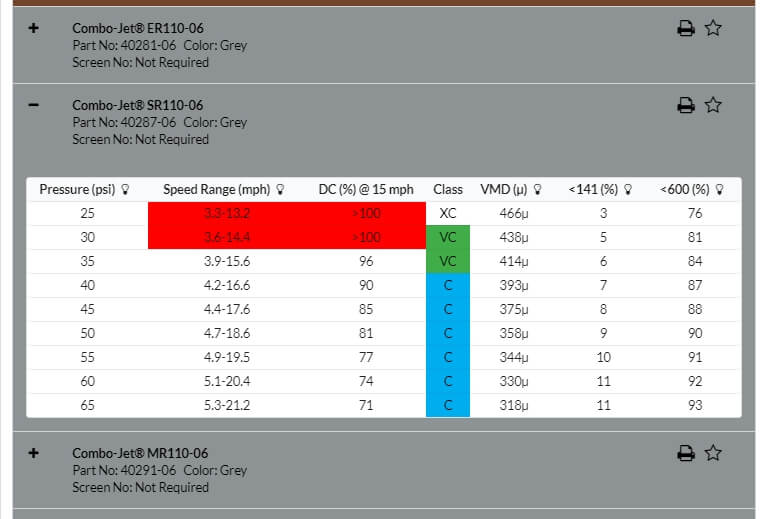
    The best tool for selecting the right nozzle size is Wilger’s Tip Wizard. This site asks for your desired average speed ( although it calls this “Max Sprayer Speed”), and reports the expected DC for a host of nozzle size solutions and pressures. It also reports maximum and minimum travel speeds and other useful information such as spray quality.

    Fig 1: The Tip Wizard is a useful tool for sizing nozzles on any PWM system. Sizing information applies to any nozzle. Spray quality information is for Wilger ComboJet nozzles only.

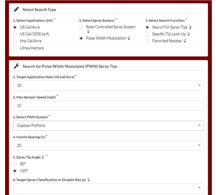
    Although intended for Wilger nozzles, the site’s sizing feature works for any nozzle brand. It asks the user which PWM system they have for the purpose of calculating the documented pressure drop across the solenoid.

    Fig 2: Tip Wizard results for the Wilger SR11006 tip at 10 gpa and 15 mph. Look for a solution that provides 60 to 80% Duty Cycle (DC).

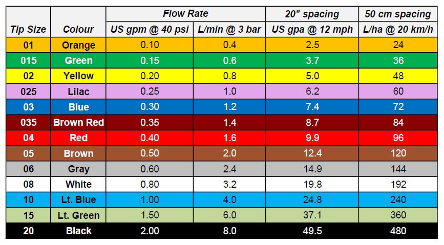
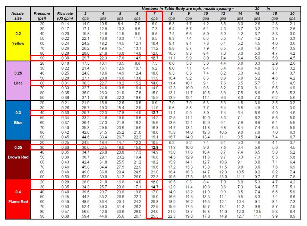
    If you don’t have access to the site, a basic calibration chart can still work with a simple trick. Recall that we use the top row to identify the desired water volume, and the table’s interior values are speeds, as described here.

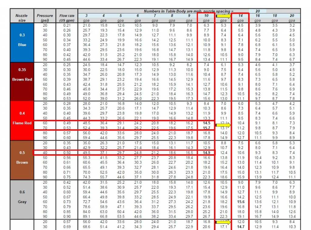
    Below are two solutions for someone wanting to apply 10 gpa at 15 mph without PWM. The correct choice depends on the required pressure to produce the needed spray quality.

    Fig 3: A conventional calibration chart, solving a 10 gpa application for 15 mph.

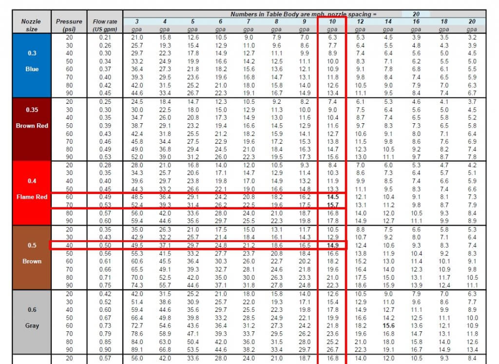
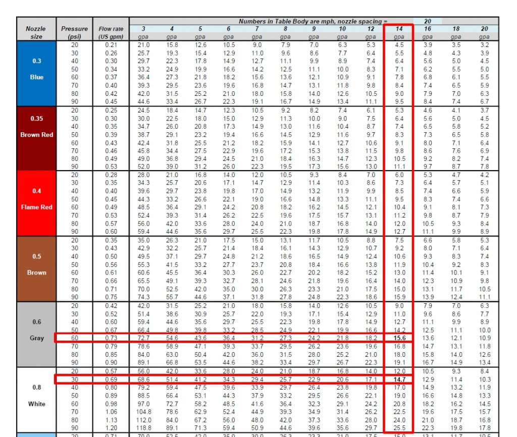
    If you want to apply the same 10 US gpa using PWM, simply solve for a larger volume that offers the right DC. For example, choosing 13 gpa will over-apply by 3 gpa, or 30%. The PWM system adjusts by running at 100-30=70% DC. If the chart doesn’t offer 13 gpa, go nearby, to 14 gpa, as we did below:

    Fig 4: By pretending to require 14 gpa instead of the actual 10 gpa, the conventional calibration chart is tricked into solving for a nozzle size that will work with PWM at 60% Duty Cycle.

    Now solve for the same target speed, 15 mph. The solution will run at 60% DC. Again, there is more than one choice, and that will depend on the spray pressure needed.

    Fig 5: Two possible solutions for achieving 10 gpa at 10 mph. An 06 nozzle at intermediate pressure or an 08 nozzle at low pressure.

    We’ve developed a template, in US or metric units, that can be customized for any water volume. Here is the same chart with 13 gpa added:

    Fig 6: A conventional calibration chart with the 13 mph speed added.

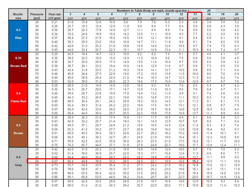
    The best solution for 10 gpa at 15 mph is the 06 size nozzle at 50 psi. This is not engraved in stone. One of the nice things about PWM is that it has inherent flexibility. Make the nozzle pressure a priority to get the correct spray quality. It really doesn’t matter whether the resulting DC is 65 or 80%, the system will still work well. Simply avoid extremes that take you below 50% or above 90%, they will limit the system’s capabilities.

    The worksheet can be downloaded below:

    It can handle any water volume or nozzle spacing by filling in the blue cells. Two additional worksheets in the file automate the process, simply enter the desired application volume, travel speed, and nozzle spacing (yellow cells), and the solution that offers the optimal duty cycle range will be highlighted in light green.

  • Putting a Number on Pesticide Waste

    Putting a Number on Pesticide Waste

    Waste (noun): an act or instance of using or expending something to no purpose.

    In agriculture, environment and economy are intertwined. Producers strive to obtain the maximum return on their inputs. They study incremental returns and avoid applying more inputs than necessary, especially if conditions don’t warrant it.  The financial incentive is powerful, and waste is a four-letter word. This applies to seed, fertilizer, and pesticide. Pesticide labels identify the rate needed to obtain the desired result, and there is no incentive to over-apply. In fact, it’s illegal.

    But there are plenty of other places where applications incur waste. As with time efficiency, it’s a good idea to identify where this waste occurs, and the only tool needed is a sharp pencil.

    When might we incur waste in the spray application process?

    • Mixing more than we need because we don’t trust the flow meter or the tank gauge entirely, or don’t know the exact field size.
    • Priming the boom before the first swath.
    • Overlapping due to curvy terrain and coarse sectional control.
    • Spray drift away from the intended swath.

    How big are the losses?

    Let’s say we have a clean sprayer and need to spray 160 acres before moving to a new crop and product. We plan to apply 10 gallons per acre and have a 1,200 gallon tank with a 120 foot boom. That means we need 1,600 gallons of spray mix in total.

    Once we’re at the field we prime the boom. Each sprayer is different, but depending on operator experience, 30 to 50 gallons are usually needed to push product from the tank to the last nozzle. Only part of that is lost to the ground, as boom sections can be shut off as soon as product has reached every nozzle of that section. We’re assuming 0.2 gallons per foot of boom is lost.

    Spraying itself is relatively straightforward. Swath and sectional control handle the overlaps, but in less ideal terrain, double application is known to account for 4 to 5% of the area to reach non-square parts of the field. This is even more likely when the outer section is 10’ or more. Early turn-on of the boom prior to leaving the headland, to allow boom to reach operating pressure, adds to this.

    Air-activated shutoff for individual nozzles reduces section size at a reasonable cost.

    With an average nozzle, we can expect about 2% of the product to airborne drift. Most airborne won’t return to the ground within the field borders, so it’s a complete loss.

    Most of the spray that travels more than 5 m after leaving boom stays airborne and should be considered a total loss from the field.

    As we finish, the pump will draw air before the tank is empty due to sloshing or foaming, and a 50 to 60 gallon remainder may not be unusual. This simulation has assumed 5% of tank volume remains.

    We also need to purge spray from the boom at cleanout, consuming approximately 0.4 gallons per foot of boom. This occurs after the field is completely sprayed and is therefore considered waste.

    So how does this add up? The following table shows the approximate losses associated with five setups.

    Table 1: Spray mix losses during a sprayer operation. Setup 1 = baseline, Setup 2 = low application volume, Setup 3 = baseline with recirculating boom, tank level monitor, and low-drift nozzles, Setup 4 = large area between cleaning, Setup 5 = large area with recirculating boom, tank level monitor, and low-drift nozzles.

    In the first scenario, we spray just 160 acres at 10 gallons per acre. Priming the boom with 0.4 gallons per foot (allowing for all associated feed lines) consumes 48 gallons, but only wastes half of that, or 1.5% of the total volume needed for the field.

    Four percent overlap consumes another 64 gallons.

    If we have 5% of the tank volume left over, that’s 60 gallons. That amount is so small it doesn’t even register on the sight gauge but nonetheless it represents another 4% of the total sprayed amount.

    Upon cleaning the boom, we need to push the spray mix out of all the  plumbing after the pump, as it has nowhere else to go. At an assumed 0.4 gallons per foot, that’s another 48 gallons or 3%.

    If we add to that a conservative 2% drift loss, it sums to a surprising 14% of the total spray volume. For those that use lower water volumes (the second scenario), the volumetric losses are slightly less, but their proportion is higher, now accounting for 23% (!) of the total spray mix.

    In the third scenario, let’s assume we use a recirculating boom that returns the initial prime volume to the tank, eliminating any waste. We’ll also upgrade to individual nozzle sectional control, reducing overlap to 1%. And, since we want to know exactly what’s left in the tank, let’s invest in an AccuVolume system to precisely monitor tank volume. This allows us to make small rate adjustments up or down to be sure as much of the mixed product goes onto the sprayed swath as possible.

    Recirculating booms allows the spray mix to pass through entire length of boom without being sprayed, saving waste during priming and allowing waste-free boom rinses.

    When the sump begins to empty, we can introduce some water from the clean water tank to push the last of the mix to the boom (a continuous rinse system makes this easy).

    An AccuVolume sensor shows the exact volume left in the tank at any slope position and with 1 gallon resolution, allowing greater accuracy when filling and emptying.

    We’ll assume our sump waste is now reduced to 12 gallons. We still need to dispose of the content of the boom somehow, so the recirculating boom offers no saving there. But let’s also add better low-drift nozzles to reduce drift by 50% (now 1% total volume). Total loss is now just 6%.

    Low-drift nozzles such as this AirMix (Agrotop) SoftDrop reduce airborne drift by 50 to 90%.

    The last two rows in the table repeat the first and third scenarios for a larger sprayed area (1000 acres) before a tank cleaning is needed. This doesn’t change the magnitude of the volumetric loss, but reduces its proportion. Percent loss is down by a factor of two from the 160 acre interval, to 3 to 7%.

    Experienced operators might cheat the system a bit by mixing the required pesticide with some extra water to make up for the plumbing waste. Doing so prevents extra pesticide from being consumed, but it doesn’t reduce the inherent inefficiency.

    Lessons

    This exercise suggests that waste from spraying is probably higher than we assumed. If we average the scenarios, there is 10 to 15% waste. At, say, $200,000 spent on pesticide for a single spraying season, that’s $20 – $30,000 worth of product and water hauled that ends up where it doesn’t belong. Beyond the time and money, there can also be environmental consequences depending on how that waste is treated.

    There are some things that can be done.

    • Know the exact area of the field to be sprayed.
    • Study your sprayer plumbing and consider improvements such as recirculating booms and continuous cleanout.
    • Improve monitoring of tank content to allow lower remainders.
    • Consider individual nozzle shutoff to improve sectional control. These are part of Pulse Width Modulation (PWM) systems, but can also be achieved with less expensive valves.
    • Plan spray operations to minimize the amount of product changeovers.
    • Consider direct injection.

    The return on investment for plumbing improvements can be high and result in considerable future savings over the life of the sprayer. It’s worth thinking about.

  • What Nozzle is This? (Field Sprayers)

    What Nozzle is This? (Field Sprayers)

    Us this handy visual guide to identify a mystery nozzle you may find on a field sprayer. We’ve included the most common low-drift nozzles found on North American, European, and Australian sprayers. The list does not contain any conventional flat fan nozzles.

    It’s in alphabetical order by manufacturer.

    First, a reminder of the ISO colour coding of nozzles by nominal flow rate, and their approximate output at normal speeds and nozzle spacings.

    ISO Flow rate colour coding and benchmark application volumes for US and metric units

    Also recall that most nozzles have markings that identify their fan angle (usually 30, 40, 65, 80, 90, 110, 120, 130, or 150 degrees, with 80 and 110 being most common) or flow rate (in US gpm, as shown in figure above).

    Albuz (manufactured in France)


    Albuz AVI (also John Deere ULAC)
    Type: Air-Induced
    Average Pressure: 60 psi
    Average Spray quality: VC
    Sizes Available: 01 – 10

    Albuz AVI Twin
    Type: Air-Induced Twin
    Average Pressure: 60 psi
    Average Spray quality: VC
    Sizes Available: 01 – 06

    Arag (manufactured in Italy)

    Arag Compact Fan Air (CFA)
    Type: Air-Induced
    Average Pressure: 60 psi
    Average Spray quality: C
    Sizes Available: 01 – 04
    Arag Compact Fan Air Ultra (CFA-U)
    Type: Air-Induced
    Average Pressure: 60 psi
    Average Spray quality: C-VC
    (intended for 2,4-D label compliance in Australia, available in 01 – 03 sizes only)
    Arag Twin Fan Low Drift (TFLD)
    Type: Pre-Orifice, suitable for PWM
    Average Pressure: 60 psi
    Average Spray Quality: VC – XC
    Sizes Available: 02 – 05

    Billericay Farm Systems (manufactured in UK)

    Billericay Farm Systems Air Bubble Jet (ABJ)
    Type: Air-Induced
    Average Pressure: 60 psi
    Average Spray Quality: M-C
    Sizes Available: 01 – 06
    Billericay Farm Systems EasyJet (known as Pulzar in UK)
    Type: Pre-Orifice, suitable for PWM
    Average Pressure: 60 psi
    Average Spray Quality: M-C
    Sizes Available: 01 – 08

    Greenleaf / Agrotop (manufactured in Germany)

    Greenleaf AirMix (made by Agrotop)
    Type: Air-Induced
    Average Pressure: 60 psi
    Average Spray Quality: C
    Sizes Available: 01 – 06
    Greenleaf SoftDrop (made by Agrotop)
    Type: Pre-orifice, suitable for PWM
    Average Pressure: 60 psi
    Average Spray Quality: XC – UC
    Sizes Available: 04 – 10
    Greenleaf TurboDrop-XL (TDXL, made by Agrotop). TDXL-D appears same, but has larger exit size and produces coarser sprays for dicamba
    Type: Air-Induced
    Average Pressure: 60 psi
    Average Spray Quality: TDXL, C-VC, TDXL-D, XC-UC
    Sizes Available: 01 – 15 (08 for -D)
    Greenleaf TADF (made by Agrotop). TADF-D appears same, but has larger exit size and produces coarser sprays for dicamba
    Type: Air-Induced Asymmetric Twin
    Average Pressure: 60 psi
    Average Spray Quality: TADF, C-VC, TADF-D, XC-UC
    Sizes Available: 01 – 15
    Greenleaf Dual Fan (DF, made by Agrotop), asymmetric twin.
    Similar to Hypro TwinCap, assembly can house two nozzles to produce a twin spray.
    Greenleaf Low Drift Dual Fan for PWM (BPDF)
    Uses AirMix nozzles with air portion removed.
    Spray Quality M – XC
    Sizes Available: 06 – 12

    Hypro Pentair / John Deere (manufactured in UK and USA)

    Hypro Guardian (Also John Deere LDX)
    Type: Pre-orifice, suitable for PWM
    Average Pressure: 40 psi
    Average Spray Quality: M
    Sizes Available: 015 – 08

    Hypro GuardianAIR (GA, also John Deere Low-Drift Air, LDA)
    Type: Air-Induced
    Average Pressure: 60 psi
    Average Spray Quality: C
    Sizes Available: 015 – 05
    Hypro Ultra Low-Drift (ULD, also John Deere ULD)
    Type: Air-Induced
    Average Pressure: 60 psi
    Average Spray Quality: C – VC
    Sizes Available: 015 – 08
    Hypro Ultra Low-Drift Max (ULDM)
    Type: Air-Induced, approved for PWM by Hypro
    Average Pressure: 60 psi
    Average Spray Quality: UC
    Sizes Available: 04 – 08
    Hypro GuardianAIR Twin (GAT, also John Deere GAT)
    Type: Air-Induced Twin
    Average Pressure: 60 psi
    Average Spray Quality: M-C
    Sizes Available: 02 – 08

    Hypro 3D (also John Deere 3D)
    Type: Pre-Orifice, suitable for PWM
    Average Pressure: 40 psi
    Average Spray Quality: M
    Sizes Available: 015 – 08
    Hypro TwinCap. Assembly can house two nozzles to produce a twin spray.

    John Deere LDM
    Type: Pre-Orifice, suitable for PWM
    Average Pressure: 60 psi
    Average Spray Quality: C – VC
    Sizes Available: 03 – 10
    John Deere LDM showing characteristic twin pre-orifice

    Lechler (manufactured in Germany)


    Lechler ID
    Type: Air-Induced
    Average Pressure: 60 psi
    Average Spray Quality: C – VC
    Sizes Available: 01 – 10

    Lechler ID3
    Type: Air-Induced
    Average Pressure: 60 psi
    Average Spray Quality: C – VC
    Sizes Available: 01 – 10

    Lechler IDTA
    Type: Air-Induced Asymmetric Twin
    Average Pressure: 60 psi
    Average Spray Quality: C
    Sizes Available: 02 – 08

    Lechler IDK (Also Hardi MiniDrift)
    Type: Air-Induced
    Average Pressure: 60 psi
    Average Spray Quality: C
    Sizes Available: 01 – 10

    Lechler IDKT (Also Hardi MiniDrift Duo)
    Type: Air-Induced Twin
    Average Pressure: 60 psi
    Average Spray Quality: C
    Sizes Available: 015 – 06

    MagnoJet (manufactured in Brazil)

    Magnojet MUG
    Approved by EPA for Dicamba in US
    Type: Air-Induced
    Average Pressure: 70 psi
    Average Spray Quality: UC
    Sizes Available: 015 – 05

    TeeJet (manufactured in USA)

    TeeJet AIXR
    Type: Air-Induced
    Average Pressure: 60 psi
    Average Spray Quality: C
    Sizes Available: 015 – 10
    TeeJet AI
    Type: Air-Induced
    Average Pressure: 60 psi
    Average Spray Quality: VC
    Sizes Available: 015 – 15
    TeeJet TurboTeeJet (TT)
    Type: Pre-orifice, suitable for PWM
    Average Pressure: 40 psi
    Average Spray Quality: M-C
    Sizes Available: 01 – 12

    TeeJet TurboTwinJet (TTJ60)
    Type: Pre-orifice Twin, suitable for PWM
    Average Pressure: 40 psi
    Average Spray Quality: M-C
    Sizes Available: 02 – 10

    TeeJet Air-Induced TurboTwinJet (AITTJ60)
    Type: Air-Induced Twin (approved for PWM by TeeJet)
    Average Pressure: 60 psi
    Average Spray Quality: C-VC
    Sizes Available: 02 – 15
    TeeJet TurboTeeJet Induction (TTI)
    Type: Air-Induced (approved for PWM by TeeJet)
    Average Pressure: 60 psi
    Average Spray Quality: XC-UC
    Sizes Available: 015 – 15

    TeeJet Twin TurboTeeJet Induction (TTI60)
    Type: Air-Induced Twin (approved for PWM by TeeJet)
    Average Pressure: 60 psi
    Average Spray Quality: XC-UC
    Sizes Available: 02 – 08
    TeeJet AI3070
    Type: Air-Induced Twin
    Average Pressure: 60 psi
    Average Spray Quality: C-VC
    Sizes Available: 015 – 05
    TeeJet AccuPulse TwinJet (APTJ)
    Type: Pre-orifice Twin, suitable for PWM
    Average Pressure: 60 psi
    Average Spray Quality: XC- UC
    Sizes Available: 015 – 08

    Wilger ComboJet (manufactured in US and Canada)


    Wilger ComboJet
    Available as ER,SR, MR, DR, and UR models. Appear similar, requires inscription to differentiate
    Type: Pre-orifice, suitable for PWM
    Average Pressure: 50 psi
    Average Spray Quality:
    ER: M
    SR: C
    MR: VC
    DR: XC
    UR: UC
    Sizes Available: 01 – 25
    Adaptor for Combojet tips on TeeJet connector
  • Nozzle Selection for Boom Sprayers

    Nozzle Selection for Boom Sprayers

    Picking the correct nozzle for a spray job can be a daunting task.  There is a lot of product selection, and a lot of different features.  We try to break the process down into four steps.

    1. Identify Your Needs

    Before making any assumptions about the right nozzle for you, review your needs and objectives. Are you trying to reduce drift? Do you want better coverage? Are you moving towards more fungicide application? Do you need a wide pressure range?

    It’s always a good idea to review your experience with your previous nozzle. What, if anything, would you like to change?

    2. Identify Flow Rates

    Most spray operations fall into one of three categories, (a) pre-seed burnoff (3 to 7 US gpa); (b) in-crop early post-emergence (7 to 10 US gpa); (c) late season application to mature canopies (10 – 20 US gpa).

    To find the right nozzle size, you need to know the application volume, the travel speed, and the nozzle spacing. Most sprayers have 20” nozzle spacing, but some have 15” spacing. Use these metric or US units charts to find the right flow rate for common nozzle spacings. Various on-line calculators from Hypro, Greenleaf / Agrotop, Lechler, or Wilger or their apps, are also helpful.

    If you use our chart, the top row lists water volumes. The columns contain travel speeds. Travel speed is somewhat flexible and can change throughout the field.

    Let’s assume the water volume is 7 gpa, and the desired application speed is 13 mph. Move down the “7 gpa” column, searching for 13 mph. You will encounter 13 mph about 5 times: 02 nozzle @ >90 psi, 025 nozzle @ 60 psi, 03 nozzle @ 40 psi, and 035 nozzle @ 30 psi (the 035 size is only offered by some manufacturers) and the 04 nozzle at about 25 psi.

    Nozzle chart, in US units, solving for 7 gpa at 13 mph. Five nozzles can produce the required flow, each at different pressures.

    Note that for the smaller nozzle sizes, the spray pressure is perhaps too high, and for the larger sizes, it is too low. Select a size that allows optimum nozzle performance and travel speed flexibility. In this example, the 025 size is optimal, producing an expected pressure of about 60 psi. The column for the 025 nozzle can now be used to predict the travel speed range from 30 psi to 90 psi, about 9 to 16 mph. For the 03 nozzle, the minimum speed would be 11 mph, too fast for some.

    For Pulse Width Modulation (PWM), slightly different rules apply. See here for instructions.

    3. Select the Nozzle Model

    For general spraying, we recommend intermediate spray qualities ranging from Medium to Very Coarse.

    These intermediate spray qualities offer good coverage at reasonable water volumes and good drift control. Their spray quality can be tailored with pressure adjustments to suit specific needs. For images, see here. In alphabetical order:

    Air Induced:

    There is plenty of selection in this popular category, all manufacturers offering similar specs and performance.

    Pulse Width Modulation:

    PWM nozzle selection is improving, but some gaps in availability remain.

    All nozzles should be operated near the middle of their pressure range, for air-induction this is 50 to 60 psi or higher, a bit less for non air-induced types. This allows maximum flexibility when travel speeds change or when spray quality is adjusted with pressure.


    For fusarium headblight, consider a twin fan nozzle.

    Keep your booms no more than 15” to 25” above the heads for best results.

    Air Induced:

    There is an excellent selection of twin fans from most manufacturers.

    Pulse Width Modulation:

    Relatively poor selection, limited flow rate ranges or spray qualities available for some models.


    For finer sprays (lower water volumes), simply increase spray pressure or consider a non-air-induced design.

    There has always been a large selection of finer sprays on the market, remnants from a time when drift was less important. Very few offer flow rates above 06 or 08, decreasing utility for PWM systems.

    Notice that conventional flat fan tips and most pre-orifice tips are absent from these lists. These nozzles are not recommended for herbicides because they produce sprays that are too fine for acceptable environmental protection (ASABE Fine and Medium). The added coverage afforded by such sprays only has value with low water volumes, and in those instances is more than offset by their higher drift and evaporation. An exception is the use of insecticides with contact mode of action targetting small insects such as flea beetles or aphids. In thes cases, finer sprays (ASABE Fine or Medium) may be required to provide effective tragetting.

    Very high flows are sometimes needed (11010 and above, usually for PWM). When this occurs, conventional flat fans have merit because the higher flow rates of any nozzle usually create coarser sprays, and even conventional tips will create sufficient coarseness to prevent drift.


    For the best drift protection, consider these tips.

    The advent of the dicamba-resistant trait in soybeans has spawned interest in very low drift tips that comply with the label requirements for these products. Although superior for drift control, they are not well suited for low volume or low-pressure spraying, nor for contact herbicides or grassy weeds, as spray retention and coverage may be poor. But they are very valuable when drift control is paramount and when higher volumes can be used to maintain adequate coverage.

    The following advice is based on the rules at the time it was written. These may be suitable for 2,4-D application in Australia under the newest APVMA guidelines (check spray quality to be sure it is VC or coarser). Many are also suited for Dicamba in Canada (must be XC or coarser), or dicamba in the US (must be on approved lists such as this one for Xtendimax or this one for Engenia, but caution is advised, some low pressure limits make them impractical. Always check that spray quality can be achieved at pressures that offer travel speed flexibility.

    Air Induced:

    Excellent selection. This market has received much attention in recent years.

    Pulse Width Modulation

    Before making a selection, check the nozzle’s recommended pressure range and the spray qualities within that range from the manufacturer info. The target pressure for these tips may differ from your expectations.

    4. Tweak and Confirm

    Under field conditions, the spray pressures which produce the desired water volumes can vary from the charts. Make sure you trust your pressure gauge reading and know the pressure drop from the gauge signal to the nozzles, particularly with PWM, where the solenoid adds additional drop. Add the pressure drop to your target pressure reading. If using a rate controller, use the pressure gauge as your speedometer to ensure optimal nozzle performance. Adjust travel speed until the nozzle pressure meets with your spray quality and pattern goals. If that speed is too slow or fast…you have the wrong size nozzle and/or water volume.

    Spray pressure is more important than travel speed – make your pressure gauge your speedometer.

  • How Low Can You Go?

    How Low Can You Go?

    Listen to an audio recording of this article by clicking here

    There’s a lot of talk about lowering the boom to reduce drift and make twin fan nozzles more effective. But how low can we actually go with a boom before striping becomes a problem?

    We’ve done some calculating and have come up with answers.

    First, a few guidelines. Tapered flat fan nozzles require overlap to generate a uniform volume distribution under the boom. Traditionally, we’ve recommended 30 to 50% overlap with fine flat fan sprays. The small droplets tended to redistribute to fill in any gaps that might occur.

    Overlap from fine sprays is less critical than from coarser sprays because the small droplets redistribute readily.

    The advent of low-drift nozzles changed that advice. This nozzle type produces fewer droplets overall, and, like all fan-style nozzles, puts the coarser ones towards the outside edges of the fan. These don’t redistribute.

    A typical flat fan spray places the coarser droplets at its periphery, and the smaller ones in the middle. When only the outed edges overlap, that can creates a band of poor coverage.

    When we had 30% overlap and these two edges met, a region of relatively few, coarse droplets was formed, and this region contained almost no small droplets. On a patternator, the volume distribution was still good. But when we measured the droplet density, we saw a deficit in coverage at the overlap.

    With low-drift nozzles, we need 100% overlap to distribute both small and large droplets uniformly under the spray swath. Too little overlap and we create bands of relatively few but large droplets that can cause striping.

    Since then, we’ve been recommending 100% overlap for low-drift sprays. This means that the pattern width at the target will be twice the nozzle spacing, and all regions under the boom receive droplets from two adjacent nozzles.

    With this adjustment, small droplets appeared throughout the spray swath, and striping was eliminated.

    That leaves the question, just how low can a boom be set without creating this problem? The following tables provide some theoretical numbers.

    Minimum boom heights for achieving 50% and 100% overlap of flat fan spray nozzles (US units)

    Minimum boom heights for achieving 50% and 100% overlap of flat fan spray nozzles (metric units)

    A word of caution: The advertised fan angle on a sprayer nozzle often differs in practice. Not only will it be slightly different by design, it also depends on spray pressure and tank mix. As a result, it’s best to do a visual check. Set the spray pressure to the minimum you expect to use. Inspect the spray patterns and set the boom height so that the edge of each nozzle pattern reaches to the middle of the next nozzle. That means your pattern width is twice the spacing and will give 100% overlap. No tape measure required.

    The tables were generated from a spreadsheet which can be downloaded here:

    • The values are theoretical and assume the fan angles are accurate. Some nozzles don’t produce the advertised fan angle. Enter your actual angle in the spreadsheet if you know it.
    • The theory assumes that the droplets at the edge of the fan always move in their projected direction. In fact, after some distance, say 50 to 75 cm, gravity pulls the droplets down and the pattern no longer widens at the same rate. The rate of pattern collapse depends on the droplet sizes.
    • Use the 0% overlap column to help with banding nozzle pattern width. Simply use the nozzle spacing column to enter your desired band width.
    • Note that angling the nozzles forward or backward decreases your minimum boom height, but depending on the deflection of the spray in the wind, this too has limits.
    • Too high a boom obviously increases drift. But patternation from overlap isn’t affected that much, largely because the pattern is now subject to aerodynamics and that becomes more important.

    Pro Tip: Attach a length of plastic hose or a large zip tie to the boom, cut to your minimum boom height. This makes it easier to see what your boom height is, from the cab or the ground.

    The bottom line is that a boom can be quite low and still allow excellent overlap and pattern uniformity from the nozzles. Yet we all know that most sprayer booms can’t reliably operate that low because they don’t control sway well enough. The ball’s in your court, sprayer manufacturers!