North American built boom sprayers have nozzle spacings of 20” (50 cm in the rest of the world), but other spacings such as 15” (37 cm) and 10” (25 cm) also exist. What are the reasons for these alternative spacings and do they offer any inherent advantages?
Why spacing matters
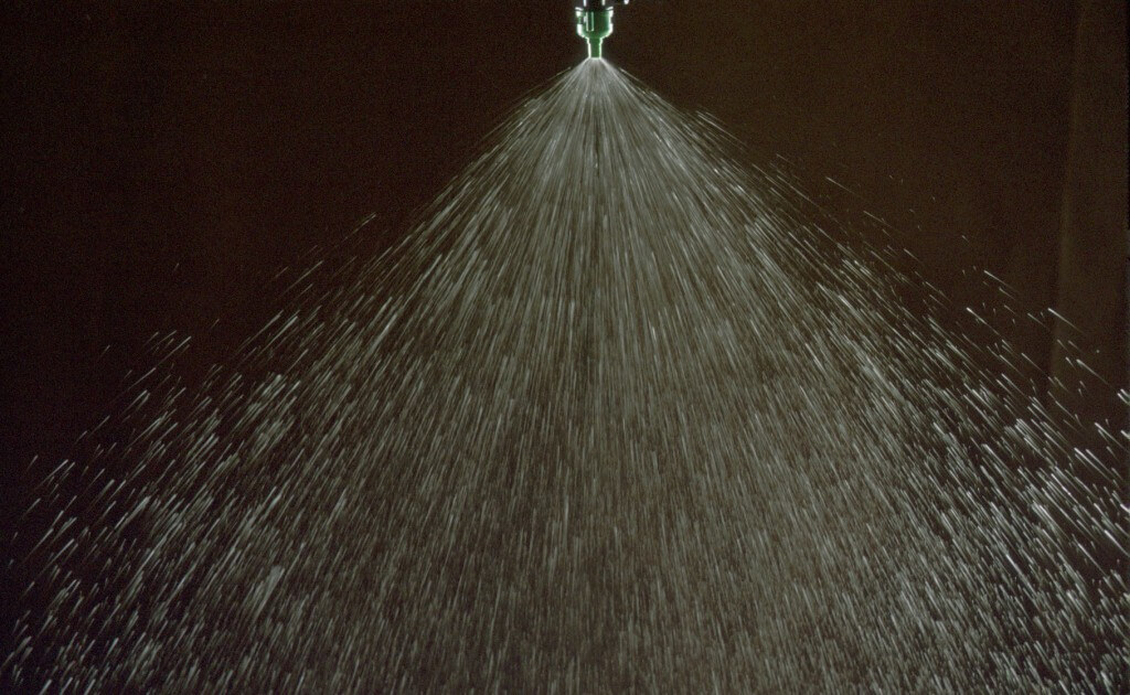
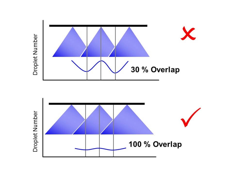
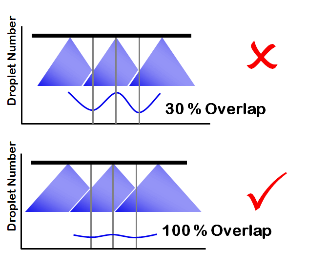
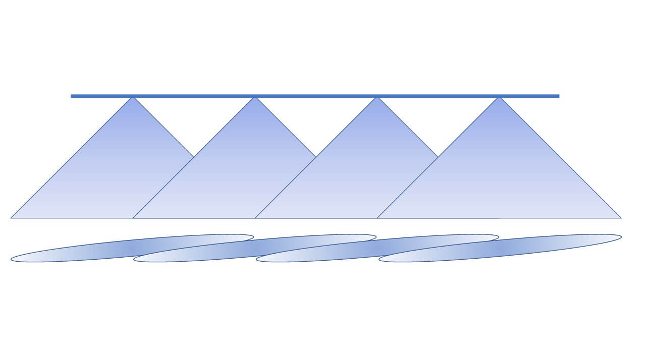
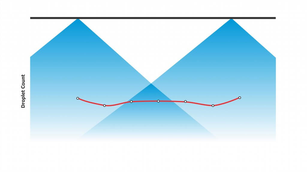
Nozzles are spaced along a boom to allow their fans (patterns) to overlap sufficiently at the target. In broadcast spraying, a uniform distribution of spray volume gives us the best chance for consistent coverage along the boom. Since flat fan nozzles produce a tapered pattern (i.e. the volume is highest in the centre and diminishes towards the edges), approximately 100% overlap (i.e. 50% from each neighbour) will produce a uniform swath.

The 100% overlap isn’t just for volumetric distribution. Flat fan spray patterns tend to have more and finer droplets in the centre and fewer and coarser droplets at the edges. All droplet sizes contribute to coverage in different ways, so the overlap ensures both number and sizes are evenly distributed along the entire boom.

The generic 20” spacing arose from long-held conventions about boom height, fan angle, and travel speed. Specifically, this spacing required a boom height of 20” to obtain good overlap of the once-dominant 80° fan angle. Combined with 0.15 to 0.3 US gallon per minute (gpm) nozzles and travel speeds of 6 to 8 mph, operators were able to apply 5 to 15 US gallons per acre (gpa) volumes. Using nozzles with smaller flow rates would generally result in nozzle blockages.
But what if we want to change any of those variables? How does this affect nozzle spacing? Figuring out the pros and cons of an alternate spacing requires a little math and some contingency management.
Boom Height Math
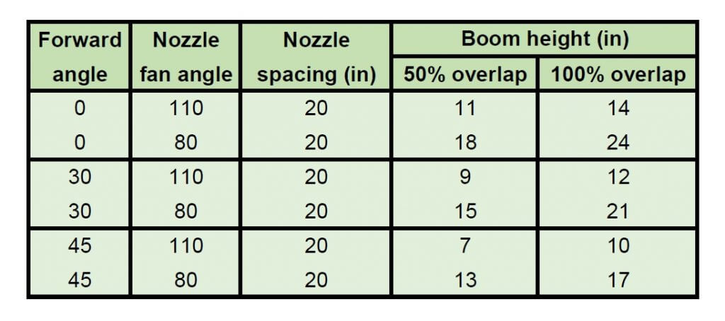
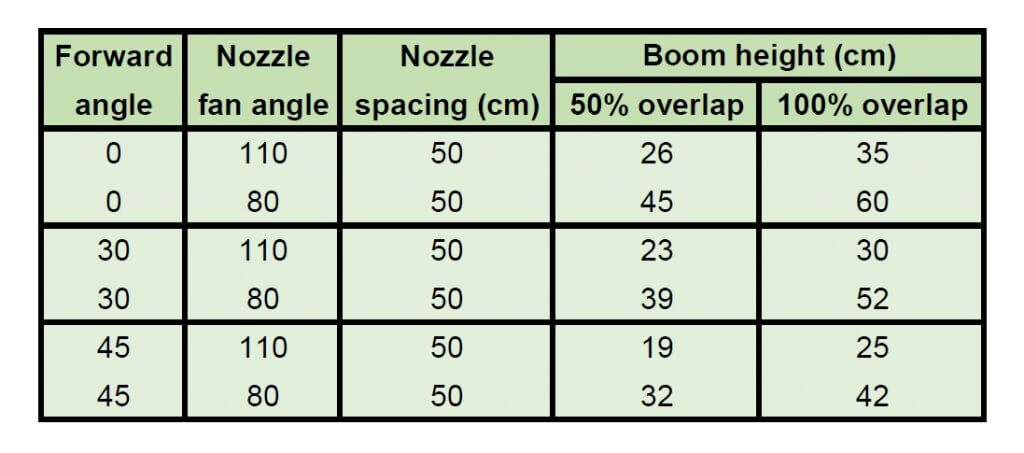
First the math. If the boom has 20” nozzle spacing and we need 100% overlap, the width of the spray pattern at target height must be two times the nozzle spacing, which is 40″. You must calculate the required fan angle and boom height to achieve this. Most nozzle catalogues have tables to help with this, or you can download a handy spreadsheet to calculate your own scenarios here.
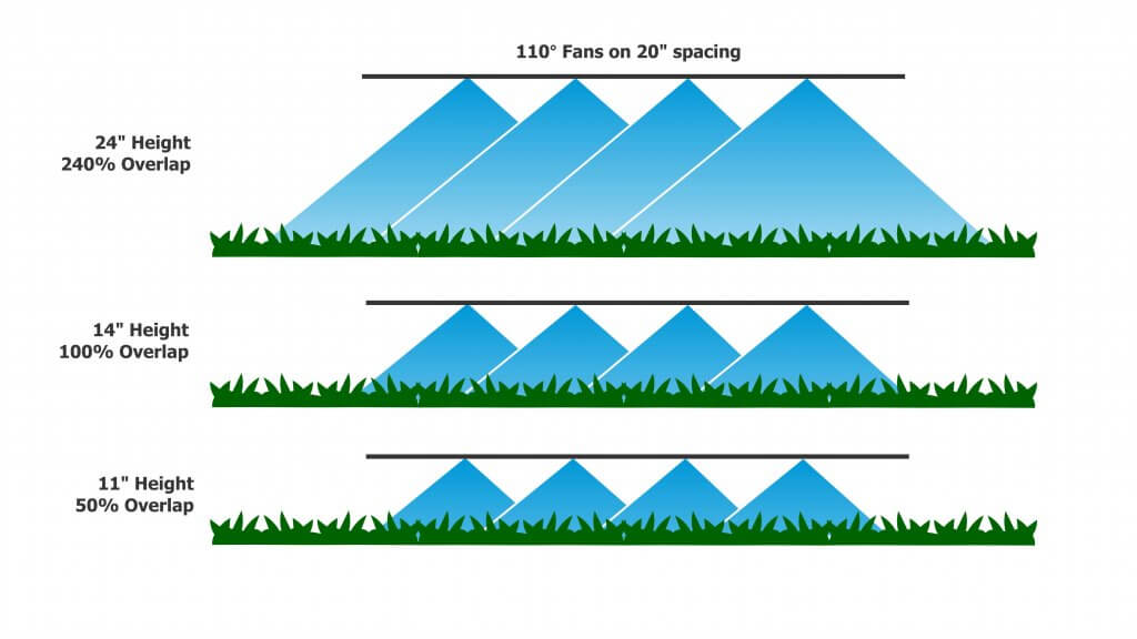
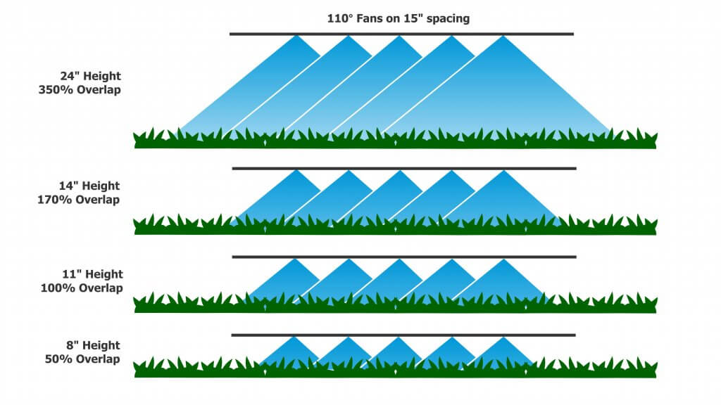
For today’s standard 110° fans, a minimum boom height of 14” is needed to achieve 100% overlap. For 15” spacing, the height is reduced to 11”. For 10” spacing, we drop to a mere 7”. However, consider that most modern suspended booms are not operated at heights less than 24” to allow for sway. At that height, there’s plenty of overlap to go around for 20″ nozzle spacing. For those booms that are able to operate at a consistent height, narrower spacings permit lower heights that will reduce drift potential significantly. Every time we halve boom height, we also halve drift potential.
By tilting the nozzles forward or backward from the vertical, we can reduce the boom height somewhat further and still get the same overlap. For example, for 20 and 15” spacings, angling nozzles forward or backwards by 30° allows us to drop the boom another 2” closer to the target.
Contingencies
A suspended boom hardly ever stays at a uniform height; It sways up and down with field conditions, topography, etc. This is why many operators set their booms above the minimum height – to prevent striping when the boom sways low. The penalty is that this increases the distance droplets need to travel, increasing drift potential and any turbulent displacement problems arising from the moving boom.
Assuming a 110° flat fan at 24” boom height, each nozzle achieves a theoretical pattern width of about 70”, which is an overlap of 70÷20=3.4-fold or 240% on 20” nozzle spacing. Given a minimally-acceptable overlap of 50% (25% from each neighbouring nozzle), the boom could be as low as 11”. For 15” spacing, the minimum height for 50% overlap is 8”, and for 10” spacing it’s 5”. This means the narrower spray patterns gain 3” to 6” in allowed downward boom movement.
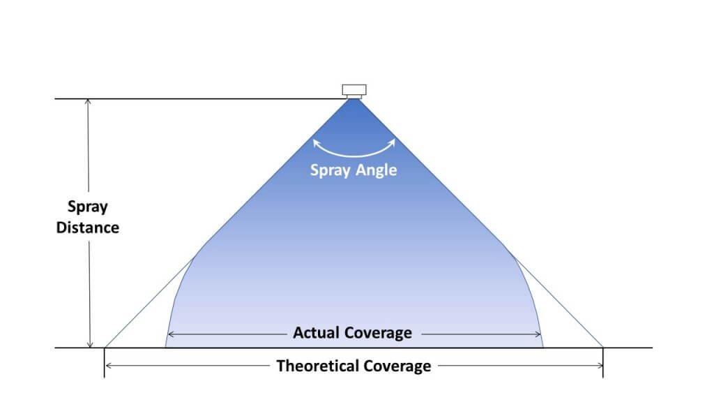
A second contingency is that spray patterns are rarely the exact value that the nozzle catalogues specify. A so-called 110° nozzle may operate at only 90°, or up to 150°, depending on the nozzle model, the spray pressure, and the tank mix. Learn more here and here. Patterns also don’t continue to grow at their rated fan angle, as droplets slow due to air-resistance and fall more vertically due to gravity. For that reason, a visual check is recommended to ensure the expected overlap is achieved.
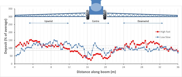
A third issue to consider is less related to boom height but nonetheless affects spray distribution. Small droplets move with air currents, and the turbulence created by large, fast sprayers creates enough turbulence to move these droplets significantly. A perfect pattern under static conditions can look quite different at a fast travel speed with a modest side wind. Low booms may help prevent some of this displacement because droplets spend less time in flight, and their average velocity is faster.
Flow Rate Math
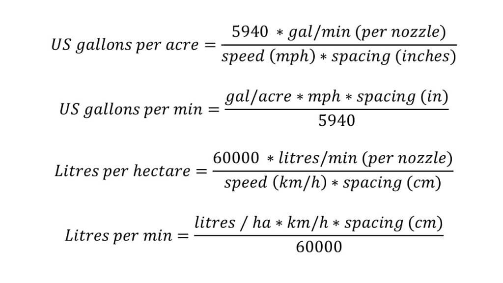
Flow rate requirements per nozzle change whenever we equip a boom at an alternate spacing. The basic formulae are shown below.
Moving from a 20″ to a 15″ spacing would require a nozzle with 0.75 of the flow rate, approximately from a 02 to 015 size, or 03 to a 025 size, or 04 to 03 size, etc.
Pulse Width Modulation
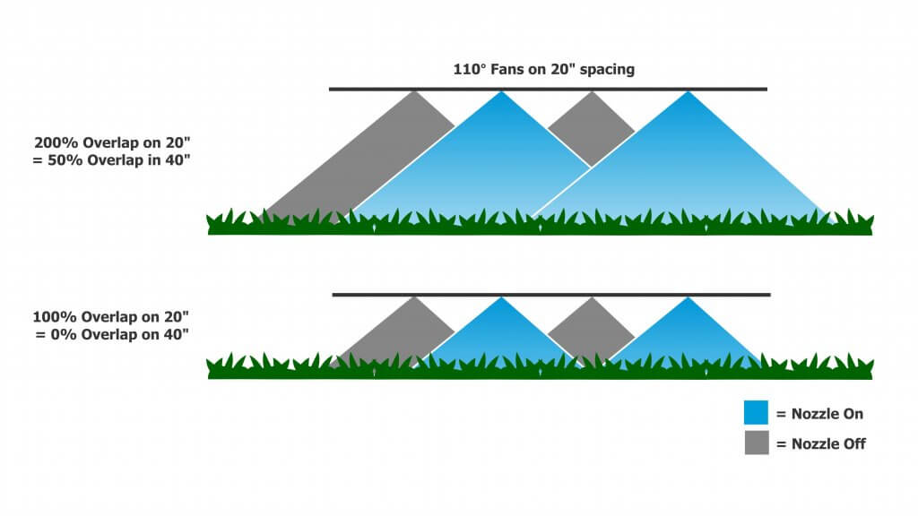
The use of Pulse Width Modulation (PWM) has increased the overlap requirement. With PWM, alternate nozzles are on a 180° timing offset from their neighbours. This means that when running >50% duty cycle, when one nozzle is temporarily off, its neighbours are on. These neighbours’ patterns must now span the gap, and 100% overlap is the absolute minimum to achieve this. PWM users therefore select the wider pattern angles and some opt for >100% overlap.
PWM Considerations
- High flows (greater than 1 US gpm at the nozzle) that are common for fertilizer top-dressing may require higher-flow PWM valves.
- Narrow spacings reduce the individual nozzle flow rates and can therefore support higher application rates before triggering a larger valve requirement.
- PWM valves aren’t cheap and for example 15″ spacing compared to 20″ spacing adds 24 valves on a 120′ boom.
Banding
We noted that 20” nozzle spacing is a standard because it corresponds to what has traditionally been achievable with available boom heights and spray pattern angles. But things can change.
Narrower spacings such as 15” originate with row crops and planter row spacings of 15” or 30”. These spacings exist so the spray pattern can be placed either over the top of a crop row, or in between the rows for banding. Using narrower fan angles and/or lower boom heights, together with “even” (as opposed to “tapered”) fans, banding sprays can be applied over the top of, or between crop rows. Or drop hoses can reach between the rows for top-dressing or directed sprays into the canopy.
Canopy Penetration
With narrower spacing, it can be argued that a greater proportion of the boom length has spray directed directly downward (corresponding to the centre of the pattern). Whether or not this translates into better penetration of a canopy is a fair question. In laboratory trials, use of 10” or 20” spacing did not improve penetration into a broadleaf canopy. But if the lower boom height afforded by the narrower spacing was utilized, some improvements in the deposit of angled sprays onto vertical targets was observed.
Adjusting to Narrower Spacings
As we showed earlier, use of 15” or 10” spacing booms for broadcast sprays requires a smaller nozzle size to achieve the same spray volumes as the 20” spacing. If boom height remains constant, narrower spacings result in greater pattern overlap which provides more latitude for sway. Alternately, lower boom heights can be used.
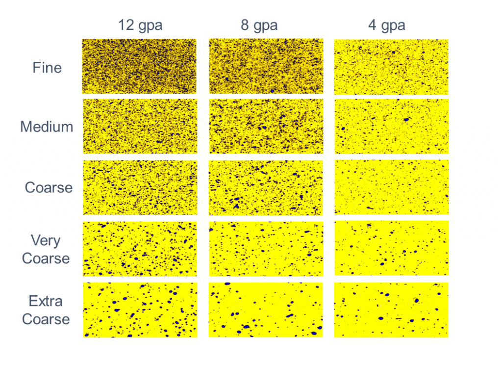
Using smaller nozzles on narrower spacing presents some challenges. Generally, smaller nozzle size means finer spray quality. If an operator wants to retain the spray quality they had on a 20″ spacing, they may opt to use lower pressure (not advisable for non-PWM systems) or swap to different nozzle design that can produce the desired spray quality at the lower flow rate.
Smaller nozzles are more prone to plugging, so that needs to be managed with filtration, filling practices and water sourcing. Be aware of the the product formulations and their requirements for filter mesh size. Most dry products specify a 50 mesh filter (or coarser). Also, check size options for nozzles. The smallest size for most nozzle models is 015, but certain PWM-specific nozzles are only available in 03 or larger.
The marriage of narrow spacings with individual nozzle shutoff can result in a versatile system capable of producing high resolution banded sprays in narrow seeded crops. For example, consider a boom with a 10” nozzle spacing spacing that matches the seeder row spacing. The operator can shift from 10” to 20” or 30” from the cab if the valve control software allows it. With accurate guidance and good boom levelling, topdressing foliar products (e.g. nutrients, fungicides) can follow the crop row precisely.
Spot Sprays
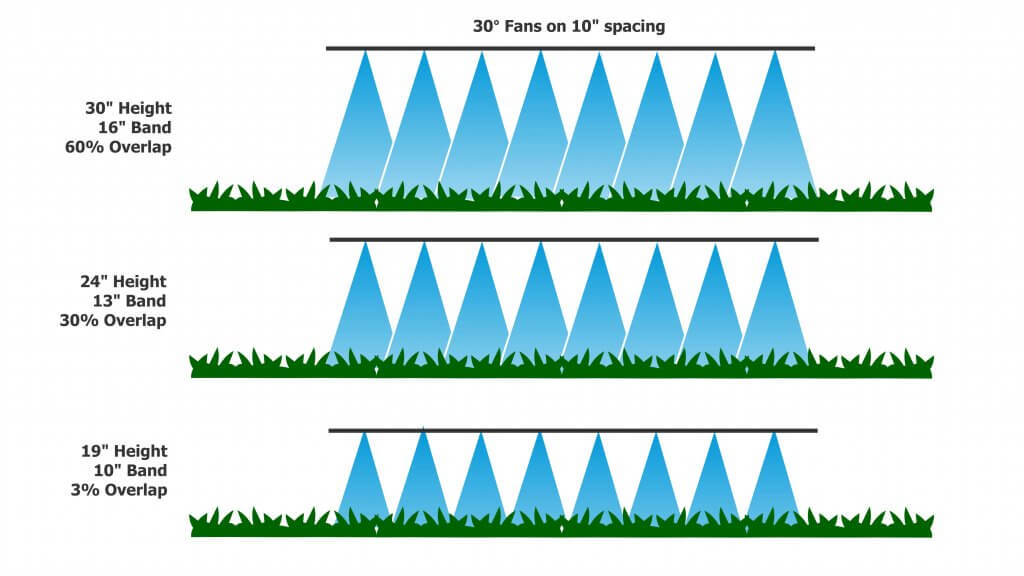
Spot sprays present a situation where compromises are needed. Some, such as WEEDit, utilize narrower nozzle spacings to allow better treatment resolution and increase product savings. Any one nozzle or sets of adjacent nozzles may be triggered by the sensor. For single nozzle activation, to preserve the value of the better resolution a uniform, narrow band of spray needs to be created. This means a 30° or 40° fan angle from a banding nozzle will be necessary. For example, a 24” boom height will result in a 13” band with a 30° fan, and an 18” band with a 40° fan. In the latter case, the dose would be diluted by 80%, wasting much of the potential savings.
Frequently, a patch of weeds will trigger several adjacent nozzles. Now these individual bands need to work together to create a uniform swath. This will inevitably require some overlap to avoid gaps, but too much overlap will result in bands where twice the dose will be applied. A tapered fan may suit this situation better. As a result of these varying needs, tolerances for spot spray boom height are even more strict than for broadcast spraying. More thoughts on spot spray nozzle selection are here.
Conclusions
Narrower nozzle spacings on a broadcast boom allow somewhat lower boom heights and these can in turn reduce drift and improve deposition of sprays. Lower flow nozzles will be needed with narrower spacings, requiring management of plugging and potentially a more drift-prone spray quality. The value of narrower spacings depends on the availability of booms that control sway, allowing them to operate at uniform, low heights.