The pump is the heart of the sprayer and a key component for producing the flow of spray material and sprayer output. Because various spraying situations require different pressures and flow rates, using the correct sprayer pump is essential to achieving desired results. In addition to sprayer considerations, a pump must also be durable enough to withstand harsh chemicals that may cause excessive wear. Even though pumps with added chemical corrosion protection are more expensive, they are a popular choice because of their durability.
Roller, centrifugal, diaphragm, and piston pumps are commonly used to apply crop protection products. Centrifugal and roller pumps are typically used for low-pressure sprayers, and diaphragm and piston pumps are more popular when high-pressure sprayers are needed (i.e., vegetables, orchards, etc.). Less common pump types include squeeze, gear, and turbine.
Pumps are typically either ground driven or powered by main or auxiliary engines, power takeoff (PTO) shafts, or hydraulic pumps. The choice of pump depends on the material to be pumped and the capacity or volume needed. However, no particular type of pump is ideal for all purposes.
Sprayer pumps can be divided into two general categories: positive displacement and non-positive displacement. Positive displacement pumps (roller, diaphragm, and piston) maintain a flow output directly proportional to the pump speed. These pumps require a pressure-relief valve and a bypass line for proper performance. Non-positive displacement pumps do not have a proportional output flow to pump speed and do not require a relief valve and bypass line. The centrifugal pump is an example of a non-positive displacement pump style. A summary of common pump types and characteristics is found in the following Table (contributions from ACE Pumps Corporation, Hypro Pumps Inc., and CDS-John Blue Company).
| Characteristic | Roller | Centrifugal | Diaphragm | Piston | Ground Driven Piston |
| Cost | Low | High | Medium | High | High |
| Displacement | Positive, self priming; Requires relief valve | Non-positive, needs priming; Relief valve not req’d | Positive, self-priming; Requires relief valve | Positive, self-priming; Requires relief valve | Positive, self-priming; Relief valve not reg’d. Runs off drive wheel and can be lifted on hydraulic-controlled applicators, or can be purchased with clutches to to disengage pump when flow is not desired. |
| Drive Mechanism | PTO, gas engines, electric motors | PTO, hydraulic drives, gas engines, electric motors | PTO, hydraulic drives, gas engines | PTO, gas engines, electric motors | Primarily ground-driven. Although less common, can be used with hydraulic drives, electric motors or gas engines. |
| Adaptability | Compact and versatile | Good for abrasive materials; Handles suspensions and slurries well. | Compact for amount of flow and pressure developed. | Wide range of spraying applications; Dependable | Wide range of spraying applications from clear liquids to suspensions. Very accurate regardless of ground speed or back pressure. Very dependable. |
| Durability | Parts to wear; replace | Very durable, not much wear | No corrosion of internal parts | Parts to wear; replace | Very durable. With basic care and maintenance, pumps can easily be in service 30 years or more. |
| Serviceability | Easy to work on, repair | Basic maintenance extends life | Low maintenance | Potential for high maintenance | Low maintenance |
| Pressure Range | up to 300 psi | up to 180 psi | up to 725 psi | up to 400 psi | up to 120 psi |
| Output Volume | 2 to 74 gpm; high volumes for size; proportional to pump speed. | up to 190 gpm; High volumes for size and weight; Proportional to pump speed. | 3.5 to 66 gpm; Proportional to pump speed. | up to 10 gpm; Proportional to pump speed, independent pressure. | 0.5 gpm to 68.4 gpm. |
| Revolutions per minute | 540, 1000 | Requires speed-up mechanism. Very efficient at higher speeds; up to 6,000 rpm. | 540 | 540 | Ground-driven. Maximum 450 rpm. |
| Notes | Best choice by farmers. | If hydraulic-driven, no PTO required. Popular in commercial ag. applications. Running pump dry i s a problem. | Good for higher pressure requirements. Popular for horticultural applications. Pump can run dry. | Similar to an engine; Low capacity. | No gpa flow variation due to pressure or ground speed changes. No concern of electric failures on controllers or radar systems. Dependable accuracy. |
Pump Efficiency
Regardless of the type of pump, the necessary flow rate must be provided at the desired pressure. Enough spray liquid should be pumped to supply the gallons per minute (gpm) required by the nozzles and the tank agitator, with a reserve capacity of 10 to 20 percent to allow for flow loss as the pump becomes worn. Unfortunately, pumps lose efficiency for a number of reasons, such as drive friction or leakage.
When estimating the pump horsepower needed for an application, efficiency (Eff) of 40 to 60 percent should be assumed. The horsepower (HP) required to drive the pump can be estimated by using the following formula:
HP = (gpm × psi) / (*1,714 × Eff)
*Constant derived when converting gallons, minutes, pounds, and inches to horsepower.
Example: How much horsepower is required to run a pump if the maximum output is 50 gpm at 40 pounds per square inch (psi)? Assume a pump efficiency of 40 percent.
HP = (50 gpm × 40 psi) / (1,714 × 0.40 Eff)
HP = 2.92
Because of inefficiencies of the drive units, electric motors should be approximately one third larger than the calculated horsepower. Gasoline engines should be one half to two thirds larger than the pump horsepower required. Ground-driven pumps that vary flow rates as ground speed changes are accurate and dependable; they are often used when applying high volumes of materials such as fertilizer.
Many pumps are PTO driven, but most modern spray pumps are hydraulic driven because of mounting versatility, ease of maintenance, and customization for individual sprayers. Charts are available to match pumps to various tractor hydraulic systems. You can access these charts by following the links to the following major pump manufacturers:
Hypro Pumps – www.hypropumps.com
ACE Pump Corporation – www.acepumps.com
CDS-John Blue Company – www.cds-johnblue.com
Hardi – North America – www.hardi-us.com
Delavan Ag Spray – www.delavanagspray.com
Watson-Marlow – www.watson-marlow.com
Pump Capacity
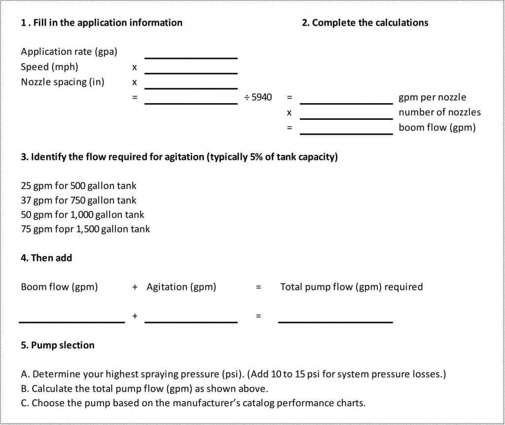
Proper pump size is an important consideration when selecting a sprayer pump. Requirements for nozzle capacity, hydraulic agitation, and overcoming the efficiency loss noted previously are essential points to consider. Nozzle capacity is determined by multiplying the number of nozzles on the boom times the output (gpm) of each nozzle for a specific application. Be sure to give consideration to the range of spray pressures that will be used for the given application. Agitation requirements typically account for another 5 percent of the sprayer tank capacity. Efficiency losses due to friction and pump wear may account for an additional 10 to 20 percent increase in the required flow rate. Spray pump manufacturers provide useful Web page worksheets to help determine pump sizes based on typical field application scenarios.
Manufacturers also make product guides available to help match sprayer pumps and hydraulic motors to the tractor’s hydraulic system (Table 2). A simple pump selection worksheet is provided at the end of this article.
No matter what type pump is used, it must be plumbed to route liquid from the pump to the spray boom with a minimum amount of restriction, a necessity for achieving the pump’s maximum rated capacity. The hoses should be the same size as the pump’s suction and discharge ports. Other recommendations include installing a pressure gauge and valve on the pressure side of the pump to measure the shut-off pressure and using a minimum number of elbows, fittings, and valves to reduce pressure losses.
Following these guidelines is necessary for delivering the highest pressures to the boom.
Pump Rotation
Pump rotation is critical for PTO and belt and- pulley driven pumps. The direction of rotation is always determined when facing the pump and drive shaft, and pumps are available in both clockwise and counter-clockwise rotation. Thus, when direct coupling shafts, the opposite rotation pump should always match the shaft. When mounting a pump with belts and pulleys, either pump rotation can be used to match the drive shaft rotation and the desired direction of the pump. Gasoline engine and electric motor shafts rotate in a counter-clockwise direction, and a tractor PTO shaft rotates in a clockwise direction.
Pump Types
Roller pumps are popular for small sprayers because of their low initial cost, compact size, ease of repair, and efficient operation at PTO speeds of 540 and 1000 revolutions per minute (rpm). Roller pumps are self-priming, positive displacement pumps, and a variety of models is available. Maximum outputs range from 2 to 75 gpm, and pressures range up to 300 psi.
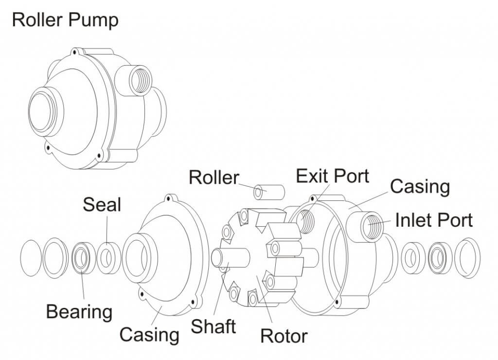
Roller pumps are usually constructed with cast iron or corrosion resistant housings (non-symmetrical in shape), rotors, four to eight rollers (either nylon, Teflon, or rubber), and seals (Viton, rubber, or leather). The type of material selected depends on the chemical being pumped. A typical roller pump is shown in Figure 1.
Nylon or Teflon rollers are the most resistant to agricultural chemicals and are recommended for multipurpose sprayers. Rubber rollers are preferred when the pump is used only for water solutions and wettable powder slurries at pressures less than 100 psi. Because sand and scale are abrasive to the rollers, the solution being pumped must not contain these materials. Polypropylene rollers wear better than either nylon or rubber rollers when applying weak solutions or solutions with little or no lubricating qualities.
Some operators have experienced problems with excessive wear of the rollers, especially when using wettable powders. Other operators have achieved long pump life by allowing the pump to run continuously when spraying with wettable powders, and by properly maintaining and storing the pump, including keeping abrasive materials out of the sprayer. Specific seal, roller, and casting materials can be selected for compatibility with certain herbicides, insecticides, fungicides, and fertilizers Consideration should also be given to the adjuvants used in the spray solution.
Centrifugal pumps are the most popular type of low-pressure sprayer. They are durable, simply constructed, and can readily handle wettable powders and abrasive materials. Because of the high output of centrifugal pumps (70 to 190 gpm), the spray solution can be agitated sufficiently even in large tanks at pressures up to 180 psi. The initial cost of a centrifugal pump is somewhat higher than that of a roller pump, but its long life and low maintenance make it an economical choice. Pump housings of cast iron, stainless steel, and polypropylene are advantageous because they withstand strong chemicals. Stainless steel pumps are ideal for use with glyphosate or other acid applications. Polypropylene pumps are lightweight and provide excellent resistance to corrosive chemicals. Figure 2 shows a typical centrifugal pump.
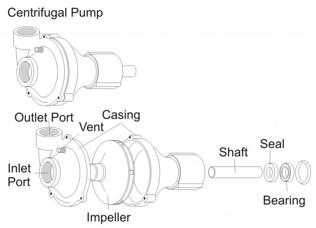
Because centrifugal pumps are not self-priming, they should be mounted below the supply tank to aid in priming. In addition, a small vent tube should be installed from the top of the pump housing to the supply tank. This positive vent line allows the pump to prime itself by “bleeding off” trapped air upon starting and when the pump is not operating.
The inlet of a centrifugal pump should never be restricted. A partially clogged suction strainer, collapsed suction line, or a suction line with insufficient capacity causes a loss of pressure control and possible damage to the pump. Centrifugal pumps can handle small pieces of foreign material without damage, so a suction strainer is not always required. If a suction strainer is used, however, it must be capable of handling the large capacities of the pump with a minimal drop in pressure across the strainer, and it must be cleaned frequently. Typical centrifugal pump plumbing would place the strainer on the pressure side of the pump.
Centrifugal pumps for low-pressure sprayers can generate pressures of up to 70 psi when the impellers are running between 3,000 and 4,500 rpm. The output volume drops off rapidly when the outlet pressure exceeds 30 to 40 psi. The decrease in volume is an advantage because the nozzle pressure is able to be controlled without a relief valve. See Figure 3 for a typical centrifugal pump performance curve. The pump performance curve describes the relationship between flow rate and pressure for the actual pump.

The need to operate at high impeller speeds requires a type of step-up speed mechanism when operating centrifugal pumps from PTO shafts. The simplest and least expensive of these mechanisms is a belt and sheave assembly. Other step-up mechanisms have planetary gears that are completely enclosed and mounted directly on the PTO shaft.
Another method of driving a centrifugal pump is with a close coupled, high speed hydraulic motor. Using the tractor hydraulic system to drive the pump keeps the tractor PTO shaft free for other uses. It is essential to consult manufacturer pump selection guides to match the proper pump to your tractor. Pumps can also be driven by direct-coupled gasoline engines when other drive mechanisms cannot be used.
Airplane pumps may be wind-driven, directly powered from the aircraft engine, or powered by an electric or hydraulic motor. The pump may also power the tank agitation system. For fixed-wing aircraft, the most common type of pump is a wind-driven centrifugal pump mounted under the aircraft (Figure 4). The propeller slipstream drives a fan mounted on the front of the pump. Some fan-driven pumps have variable pitch blades that allow for changing pump speed, and thus output. The centrifugal pumps commonly used on aircraft produce high volumes (up to 200 gpm) at typically low pressure, usually ranging between 10 and 100 psi. These pumps usually require operating speeds from 1,000 to 5,000 rpm.

Diaphragm pumps are popular when higher pressures are needed for applying foliar herbicides, insecticides, and fungicides. Models are available that provide maximum outputs ranging from 3.5 to 60 gpm and maximum pressures ranging from 200 to 700 psi. These pumps are extremely durable because all moving parts are sealed in an oil bath and spray solutions. Diaphragm pumps are self-priming and considered positive displacement pumps. Figure 5 shows a typical diaphragm pump. Smaller electric diaphragm pumps (Figure 6) are available for use by homeowners, ranchers, and hobbyists to apply pest control products. A good example is a spray system mounted on an ATV for spraying pastures and rights-of-way.

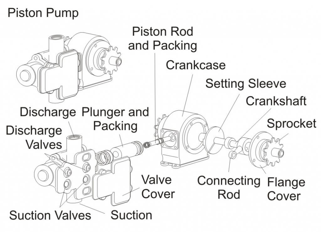
Piston pumps are positive displacement pumps that are favored by many users for their priming ease, higher pressure capability, and constant volume spraying. Piston pumps are often used to apply crop protection products and fertilizers in combination with a ground drive so that flow rate stays proportional to ground speed and application rates remain constant. A pressure relief valve is required, though. Figure 7 is an example of a piston pump used to accurately meter liquid fertilizers.
Turbine pumps are also available for low‑pressure sprayers. A turbine pump consists of a rotating turbine within an enclosed housing. These pumps are similar to centrifugal pumps, except they provide higher flow capacity and pressures of up to 70 psi when mounted directly on a 1,000 rpm PTO shaft, eliminating the need for step‑up mechanisms. Because of the close tolerances between the turbine blades and the casing, turbine pumps are better adapted for clean fluids of low viscosity but may have difficulty with wettable powders and suspensions. Figure 8 shows a typical turbine pump.

Gear pumps are positive displacement pumps capable of providing a smooth, low-volume, continuous flow of material. Gear pumps are typically two gears meshing together revolving in opposite directions within a casing. Abrasive materials such as wettable powders rapidly wear the gears and pump housing. Figure 9 shows a typical gear pump.

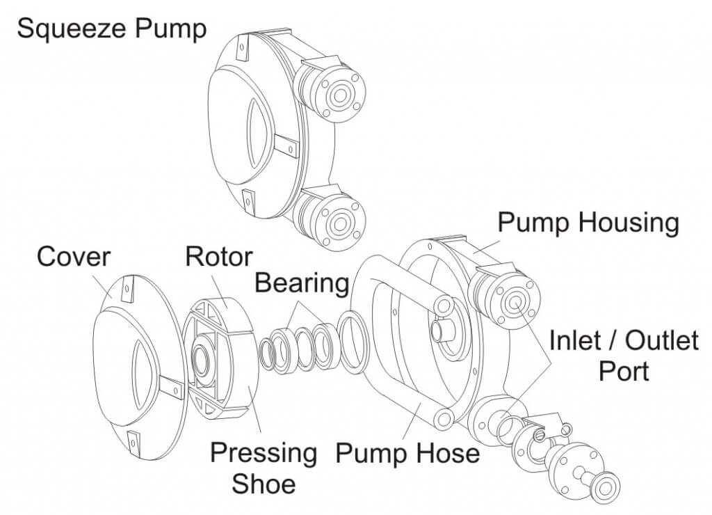
Squeeze pumps are low-pressure, positive displacement pumps with output proportional to speed. Pump flow is created when liquid is trapped by squeezing the hose between a roller and casing. Pump flow is determined by the size and number of hoses. This pump is ideally suited for metering small quantities of fertilizers or pesticides and would be practical for injection-type pumping systems. Figure 10 shows a typical squeeze pump.
Pump Maintenance
Proper pump maintenance is critical for maximum pump life. Regular cleaning is essential to removing all chemical residues and preventing wear to the pump from corrosive solutions. Do not allow spray solutions to remain in the sprayer for extended periods of time. Using lightweight antifreeze or a motor oil as the final spray solution after cleaning can preserve the pump during a period of non-use.
Pump Selection Worksheet
Acknowledgements
Excerpts for this article were adapted with permission from University of Illinois Circular 1192 developed by Loren Bode and Jack Butler (May 1981), Extension Agricultural Engineer and Professor of Agricultural Engineering, Univerity of Illinois at Urbana-Champaign. Contributions for this article were also received from ACE Pumps Corporation; Hypro Pumps Inc.,; and CDS-John Blue Company.
For more information on pump selection, check out this article.