Category: Spray Basics

  • Pumps for Applying Crop Protection Products

    Pumps for Applying Crop Protection Products

    The pump is the heart of the sprayer and a key component for producing the flow of spray material and sprayer output. Because various spraying situations require different pressures and flow rates, using the correct sprayer pump is essential to achieving desired results. In addition to sprayer considerations, a pump must also be durable enough to withstand harsh chemicals that may cause excessive wear. Even though pumps with added chemical corrosion protection are more expensive, they are a popular choice because of their durability.

    Roller, centrifugal, diaphragm, and piston pumps are commonly used to apply crop protection products. Centrifugal and roller pumps are typically used for low-pressure sprayers, and diaphragm and piston pumps are more popular when high-pressure sprayers are needed (i.e., vegetables, orchards, etc.). Less common pump types include squeeze, gear, and turbine.

    Pumps are typically either ground driven or powered by main or auxiliary engines, power takeoff (PTO) shafts, or hydraulic pumps. The choice of pump depends on the material to be pumped and the capacity or volume needed. However, no particular type of pump is ideal for all purposes.

    Sprayer pumps can be divided into two general categories: positive displacement and non-positive displacement. Positive displacement pumps (roller, diaphragm, and piston) maintain a flow output directly proportional to the pump speed. These pumps require a pressure-relief valve and a bypass line for proper performance. Non-positive displacement pumps do not have a proportional output flow to pump speed and do not require a relief valve and bypass line. The centrifugal pump is an example of a non-positive displacement pump style. A summary of common pump types and characteristics is found in the following Table (contributions from ACE Pumps Corporation, Hypro Pumps Inc., and CDS-John Blue Company).

    Characteristic

    Roller

    CentrifugalDiaphragmPiston

    Ground Driven Piston

    Cost LowHighMediumHigh

    High

    DisplacementPositive, self priming; Requires relief valveNon-positive, needs priming; Relief valve not req’dPositive, self-priming; Requires relief valvePositive, self-priming; Requires relief valvePositive, self-priming; Relief valve not reg’d. Runs off drive wheel and can be lifted on hydraulic-controlled applicators, or can be purchased with clutches to to disengage pump when flow is not desired.
    Drive MechanismPTO, gas engines, electric motorsPTO, hydraulic drives, gas engines, electric motorsPTO, hydraulic drives, gas enginesPTO, gas engines, electric motorsPrimarily ground-driven. Although less common, can be used with hydraulic drives, electric motors or gas engines.
    AdaptabilityCompact and versatileGood for abrasive materials; Handles suspensions and slurries well.Compact for amount of flow and pressure developed.Wide range of spraying applications; DependableWide range of spraying applications from clear liquids to suspensions. Very accurate regardless of ground speed or back pressure. Very dependable.
    DurabilityParts to wear; replaceVery durable, not much wearNo corrosion of internal partsParts to wear; replaceVery durable. With basic care and maintenance, pumps can easily be in service 30 years or more.
    ServiceabilityEasy to work on, repairBasic maintenance extends lifeLow maintenancePotential for high maintenanceLow maintenance
    Pressure Rangeup to 300 psiup to 180 psiup to 725 psiup to 400 psiup to 120 psi
    Output Volume2 to 74 gpm; high volumes for size; proportional to pump speed.up to 190 gpm; High volumes for size and weight; Proportional to pump speed.3.5 to 66 gpm; Proportional to pump speed.up to 10 gpm; Proportional to pump speed, independent pressure.0.5 gpm to 68.4 gpm.
    Revolutions per minute540, 1000Requires speed-up mechanism. Very efficient at higher speeds; up to 6,000 rpm.540540Ground-driven. Maximum 450 rpm.
    NotesBest choice by farmers.If hydraulic-driven, no PTO required. Popular in commercial ag. applications. Running pump dry i s a problem.Good for higher pressure requirements. Popular for horticultural applications. Pump can run dry.Similar to an engine; Low capacity.No gpa flow variation due to pressure or ground speed changes. No concern of electric failures on controllers or radar systems. Dependable accuracy.

    Pump Efficiency

    Regardless of the type of pump, the necessary flow rate must be provided at the desired pressure. Enough spray liquid should be pumped to supply the gallons per minute (gpm) required by the nozzles and the tank agitator, with a reserve capacity of 10 to 20 percent to allow for flow loss as the pump becomes worn. Unfortunately, pumps lose efficiency for a number of reasons, such as drive friction or leakage.

    When estimating the pump horsepower needed for an application, efficiency (Eff) of 40 to 60 percent should be assumed. The horsepower (HP) required to drive the pump can be estimated by using the following formula:

    HP = (gpm × psi) / (*1,714 × Eff)
    *Constant derived when converting gallons, minutes, pounds, and inches to horsepower.

    Example: How much horsepower is required to run a pump if the maximum output is 50 gpm at 40 pounds per square inch (psi)? Assume a pump efficiency of 40 percent.

    HP = (50 gpm × 40 psi) / (1,714 × 0.40 Eff)
    HP = 2.92

    Because of inefficiencies of the drive units, electric motors should be approximately one third larger than the calculated horsepower. Gasoline engines should be one half to two thirds larger than the pump horsepower required. Ground-driven pumps that vary flow rates as ground speed changes are accurate and dependable; they are often used when applying high volumes of materials such as fertilizer.

    Many pumps are PTO driven, but most modern spray pumps are hydraulic driven because of mounting versatility, ease of maintenance, and customization for individual sprayers. Charts are available to match pumps to various tractor hydraulic systems. You can access these charts by following the links to the following major pump manufacturers:

    Hypro Pumps – www.hypropumps.com
    ACE Pump Corporation – www.acepumps.com
    CDS-John Blue Company – www.cds-johnblue.com
    Hardi – North America – www.hardi-us.com
    Delavan Ag Spray – www.delavanagspray.com
    Watson-Marlow – www.watson-marlow.com

    Pump Capacity

    Proper pump size is an important consideration when selecting a sprayer pump. Requirements for nozzle capacity, hydraulic agitation, and overcoming the efficiency loss noted previously are essential points to consider. Nozzle capacity is determined by multiplying the number of nozzles on the boom times the output (gpm) of each nozzle for a specific application. Be sure to give consideration to the range of spray pressures that will be used for the given application. Agitation requirements typically account for another 5 percent of the sprayer tank capacity. Efficiency losses due to friction and pump wear may account for an additional 10 to 20 percent increase in the required flow rate. Spray pump manufacturers provide useful Web page worksheets to help determine pump sizes based on typical field application scenarios.

    Manufacturers also make product guides available to help match sprayer pumps and hydraulic motors to the tractor’s hydraulic system (Table 2). A simple pump selection worksheet is provided at the end of this article.

    No matter what type pump is used, it must be plumbed to route liquid from the pump to the spray boom with a minimum amount of restriction, a necessity for achieving the pump’s maximum rated capacity. The hoses should be the same size as the pump’s suction and discharge ports. Other recommendations include installing a pressure gauge and valve on the pressure side of the pump to measure the shut-off pressure and using a minimum number of elbows, fittings, and valves to reduce pressure losses.

    Following these guidelines is necessary for delivering the highest pressures to the boom.

    Pump Rotation

    Pump rotation is critical for PTO and belt and- pulley driven pumps. The direction of rotation is always determined when facing the pump and drive shaft, and pumps are available in both clockwise and counter-clockwise rotation. Thus, when direct coupling shafts, the opposite rotation pump should always match the shaft. When mounting a pump with belts and pulleys, either pump rotation can be used to match the drive shaft rotation and the desired direction of the pump. Gasoline engine and electric motor shafts rotate in a counter-clockwise direction, and a tractor PTO shaft rotates in a clockwise direction.

    Pump Types

    Roller pumps are popular for small sprayers because of their low initial cost, compact size, ease of repair, and efficient operation at PTO speeds of 540 and 1000 revolutions per minute (rpm). Roller pumps are self-priming, positive displacement pumps, and a variety of models is available. Maximum outputs range from 2 to 75 gpm, and pressures range up to 300 psi.
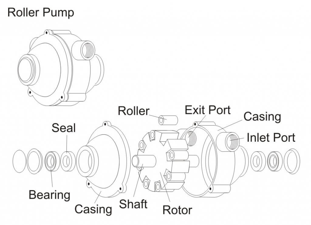
    Figure 1 - Roller Pump
    Figure 1 – Roller Pump

    Roller pumps are usually constructed with cast iron or corrosion resistant housings (non-symmetrical in shape), rotors, four to eight rollers (either nylon, Teflon, or rubber), and seals (Viton, rubber, or leather). The type of material selected depends on the chemical being pumped. A typical roller pump is shown in Figure 1.

    Nylon or Teflon rollers are the most resistant to agricultural chemicals and are recommended for multipurpose sprayers. Rubber rollers are preferred when the pump is used only for water solutions and wettable powder slurries at pressures less than 100 psi. Because sand and scale are abrasive to the rollers, the solution being pumped must not contain these materials. Polypropylene rollers wear better than either nylon or rubber rollers when applying weak solutions or solutions with little or no lubricating qualities.

    Some operators have experienced problems with excessive wear of the rollers, especially when using wettable powders. Other operators have achieved long pump life by allowing the pump to run continuously when spraying with wettable powders, and by properly maintaining and storing the pump, including keeping abrasive materials out of the sprayer. Specific seal, roller, and casting materials can be selected for compatibility with certain herbicides, insecticides, fungicides, and fertilizers Consideration should also be given to the adjuvants used in the spray solution.

    Centrifugal pumps are the most popular type of low-pressure sprayer. They are durable, simply constructed, and can readily handle wettable powders and abrasive materials. Because of the high output of centrifugal pumps (70 to 190 gpm), the spray solution can be agitated sufficiently even in large tanks at pressures up to 180 psi. The initial cost of a centrifugal pump is somewhat higher than that of a roller pump, but its long life and low maintenance make it an economical choice. Pump housings of cast iron, stainless steel, and polypropylene are advantageous because they withstand strong chemicals. Stainless steel pumps are ideal for use with glyphosate or other acid applications. Polypropylene pumps are lightweight and provide excellent resistance to corrosive chemicals. Figure 2 shows a typical centrifugal pump.
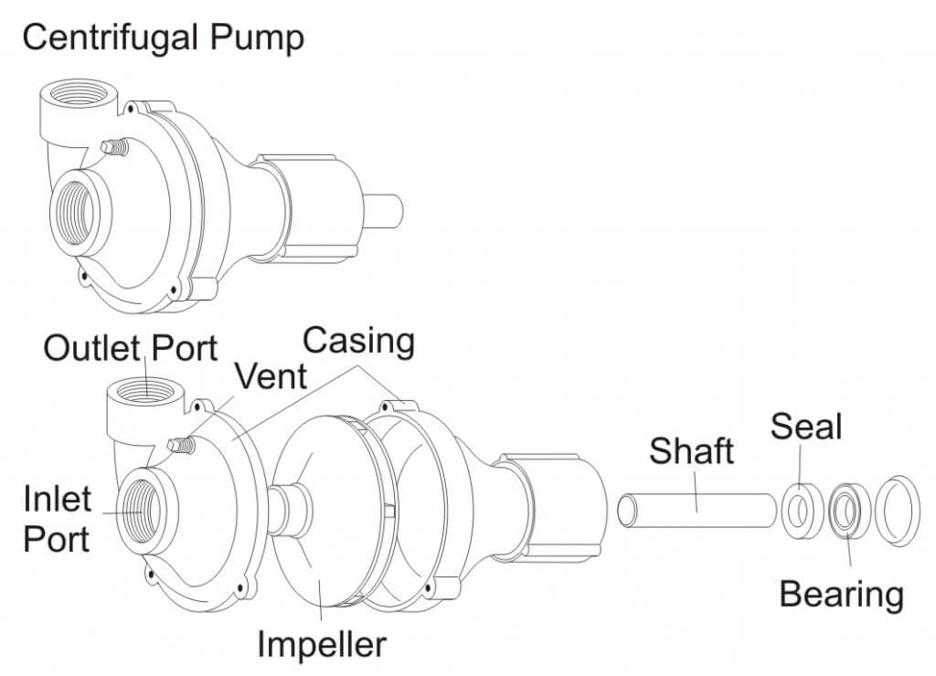
    Centrifugal Pump – Exploded View.

    Because centrifugal pumps are not self-priming, they should be mounted below the supply tank to aid in priming. In addition, a small vent tube should be installed from the top of the pump housing to the supply tank. This positive vent line allows the pump to prime itself by “bleeding off” trapped air upon starting and when the pump is not operating.

    The inlet of a centrifugal pump should never be restricted. A partially clogged suction strainer, collapsed suction line, or a suction line with insufficient capacity causes a loss of pressure control and possible damage to the pump. Centrifugal pumps can handle small pieces of foreign material without damage, so a suction strainer is not always required. If a suction strainer is used, however, it must be capable of handling the large capacities of the pump with a minimal drop in pressure across the strainer, and it must be cleaned frequently. Typical centrifugal pump plumbing would place the strainer on the pressure side of the pump.

    Centrifugal pumps for low-pressure sprayers can generate pressures of up to 70 psi when the impellers are running between 3,000 and 4,500 rpm. The output volume drops off rapidly when the outlet pressure exceeds 30 to 40 psi. The decrease in volume is an advantage because the nozzle pressure is able to be controlled without a relief valve. See Figure 3 for a typical centrifugal pump performance curve. The pump performance curve describes the relationship between flow rate and pressure for the actual pump.

    Figure 2 - Centrifugal Pump
    Figure 3 – Centrifugal Pump Performance Graph

    The need to operate at high impeller speeds requires a type of step-up speed mechanism when operating centrifugal pumps from PTO shafts. The simplest and least expensive of these mechanisms is a belt and sheave assembly. Other step-up mechanisms have planetary gears that are completely enclosed and mounted directly on the PTO shaft.

    Another method of driving a centrifugal pump is with a close coupled, high speed hydraulic motor. Using the tractor hydraulic system to drive the pump keeps the tractor PTO shaft free for other uses. It is essential to consult manufacturer pump selection guides to match the proper pump to your tractor. Pumps can also be driven by direct-coupled gasoline engines when other drive mechanisms cannot be used.

    Airplane pumps may be wind-driven, directly powered from the aircraft engine, or powered by an electric or hydraulic motor. The pump may also power the tank agitation system. For fixed-wing aircraft, the most common type of pump is a wind-driven centrifugal pump mounted under the aircraft (Figure 4). The propeller slipstream drives a fan mounted on the front of the pump. Some fan-driven pumps have variable pitch blades that allow for changing pump speed, and thus output. The centrifugal pumps commonly used on aircraft produce high volumes (up to 200 gpm) at typically low pressure, usually ranging between 10 and 100 psi. These pumps usually require operating speeds from 1,000 to 5,000 rpm.

    Figure 4 - Airplane Pump
    Figure 4 – Airplane Pump

    Diaphragm pumps are popular when higher pressures are needed for applying foliar herbicides, insecticides, and fungicides. Models are available that provide maximum outputs ranging from 3.5 to 60 gpm and maximum pressures ranging from 200 to 700 psi. These pumps are extremely durable because all moving parts are sealed in an oil bath and spray solutions. Diaphragm pumps are self-priming and considered positive displacement pumps. Figure 5 shows a typical diaphragm pump. Smaller electric diaphragm pumps (Figure 6) are available for use by homeowners, ranchers, and hobbyists to apply pest control products. A good example is a spray system mounted on an ATV for spraying pastures and rights-of-way.

    Figure 5 - Diaphragm Pump
    Figure 5 – Diaphragm Pump

    Piston pumps are positive displacement pumps that are favored by many users for their priming ease, higher pressure capability, and constant volume spraying. Piston pumps are often used to apply crop protection products and fertilizers in combination with a ground drive so that flow rate stays proportional to ground speed and application rates remain constant. A pressure relief valve is required, though. Figure 7 is an example of a piston pump used to accurately meter liquid fertilizers.
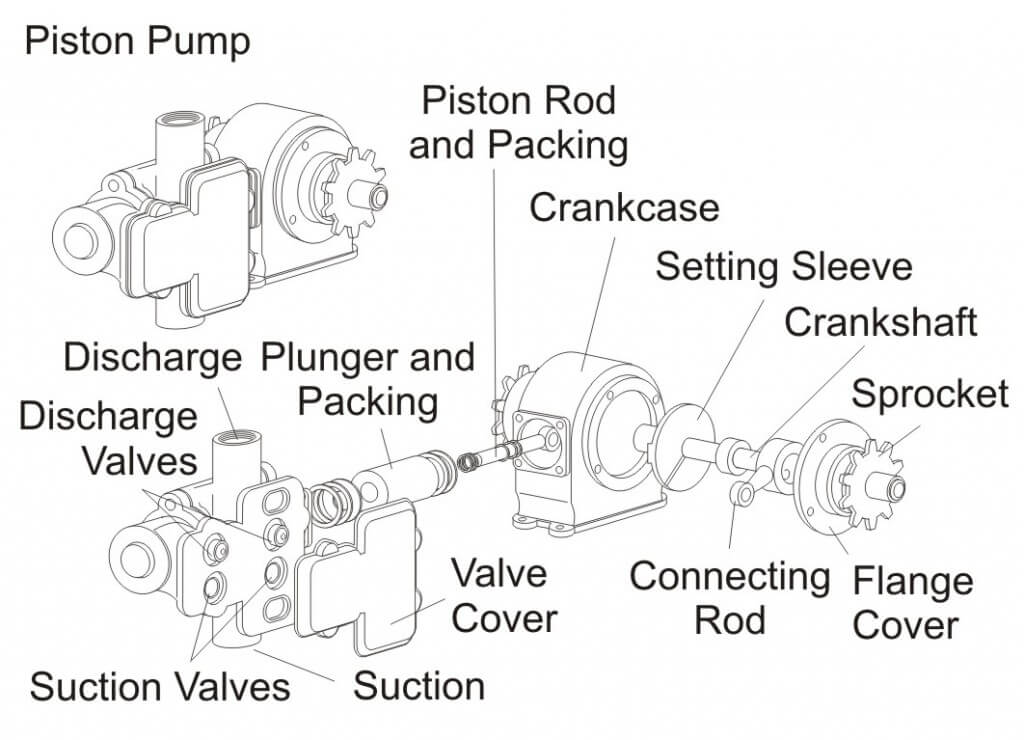
    Figure 7 - Piston Pump
    Figure 7 – Piston Pump

    Turbine pumps are also available for low‑pressure sprayers. A turbine pump consists of a rotating turbine within an enclosed housing. These pumps are similar to centrifugal pumps, except they provide higher flow capacity and pressures of up to 70 psi when mounted directly on a 1,000 rpm PTO shaft, eliminating the need for step‑up mechanisms. Because of the close tolerances between the turbine blades and the casing, turbine pumps are better adapted for clean fluids of low viscosity but may have difficulty with wettable powders and suspensions. Figure 8 shows a typical turbine pump.

    Figure 8 - Turbine Pump
    Figure 8 – Turbine Pump

    Gear pumps are positive displacement pumps capable of providing a smooth, low-volume, continuous flow of material. Gear pumps are typically two gears meshing together revolving in opposite directions within a casing. Abrasive materials such as wettable powders rapidly wear the gears and pump housing. Figure 9 shows a typical gear pump.

    Figure 9 - Gear Pump
    Figure 9 – Gear Pump

    Squeeze pumps are low-pressure, positive displacement pumps with output proportional to speed. Pump flow is created when liquid is trapped by squeezing the hose between a roller and casing. Pump flow is determined by the size and number of hoses. This pump is ideally suited for metering small quantities of fertilizers or pesticides and would be practical for injection-type pumping systems. Figure 10 shows a typical squeeze pump.
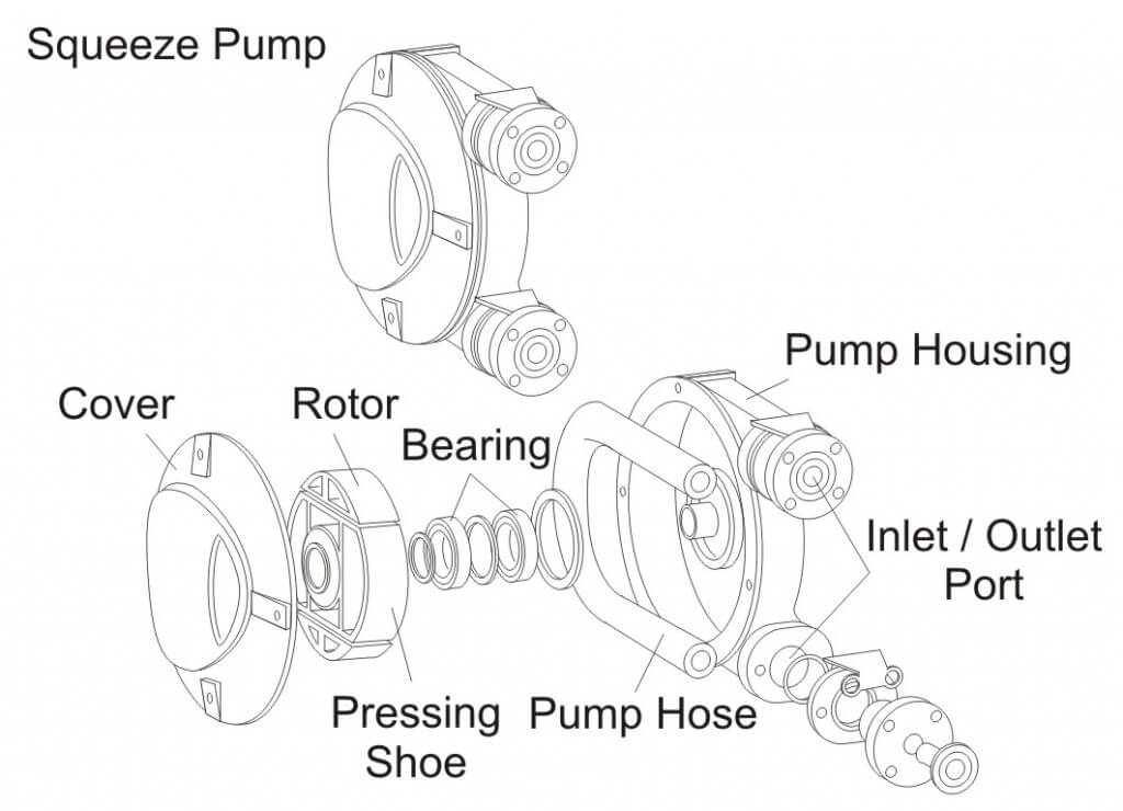
    Figure 10 - Squeeze Pump
    Figure 10 – Squeeze Pump

    Pump Maintenance

    Proper pump maintenance is critical for maximum pump life. Regular cleaning is essential to removing all chemical residues and preventing wear to the pump from corrosive solutions. Do not allow spray solutions to remain in the sprayer for extended periods of time. Using lightweight antifreeze or a motor oil as the final spray solution after cleaning can preserve the pump during a period of non-use.

    Pump Selection Worksheet
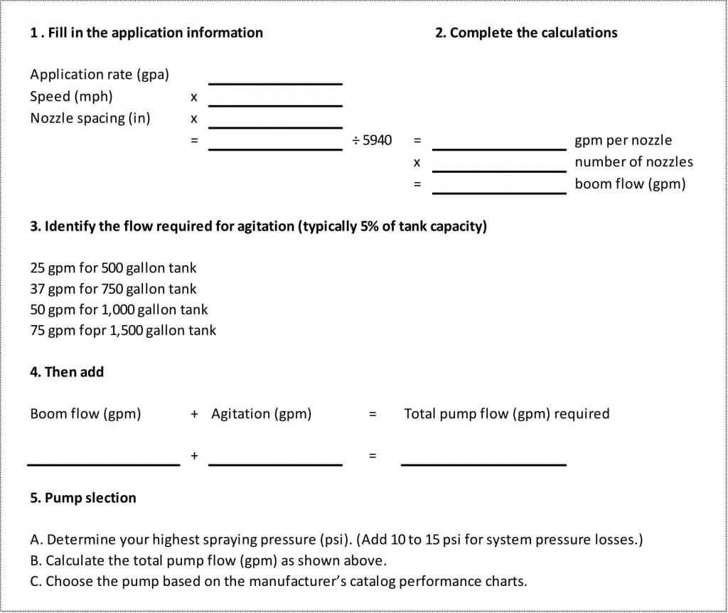
    2016_Choosing_Pump_Calculations

    Acknowledgements

    Excerpts for this article were adapted with permission from University of Illinois Circular 1192 developed by Loren Bode and Jack Butler (May 1981), Extension Agricultural Engineer and Professor of Agricultural Engineering, Univerity of Illinois at Urbana-Champaign. Contributions for this article were also received from ACE Pumps Corporation; Hypro Pumps Inc.,; and CDS-John Blue Company.

    For more information on pump selection, check out this article.
  • Sprayer Wheel Maintenance

    Sprayer Wheel Maintenance

    This article was co-written with Murray Thiessen, Consulting Agricultural Mechanic.

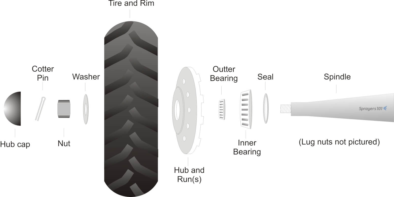
    Sprayer wheel assemblies should be cleaned and inspected as part of regular annual maintenance. Wheel bearing maintenance before long-term storage may prevent water from corroding the bearings. The exploded diagram details the parts found in a typical trailed air-assist sprayer wheel assembly.

    Exploded diagram of typical airblast sprayer wheel assembly.
    Exploded diagram of typical airblast sprayer wheel assembly.

    The following procedure was performed on a 2012 Durand-Wayland sprayer by Mr. Murray Thiessen, Consulting Agricultural Mechanic and renowned “Sprayer Whisperer”. The steps are applicable to most sprayer makes and models. The entire process should take approximately half-an-hour per wheel.

    Step 1

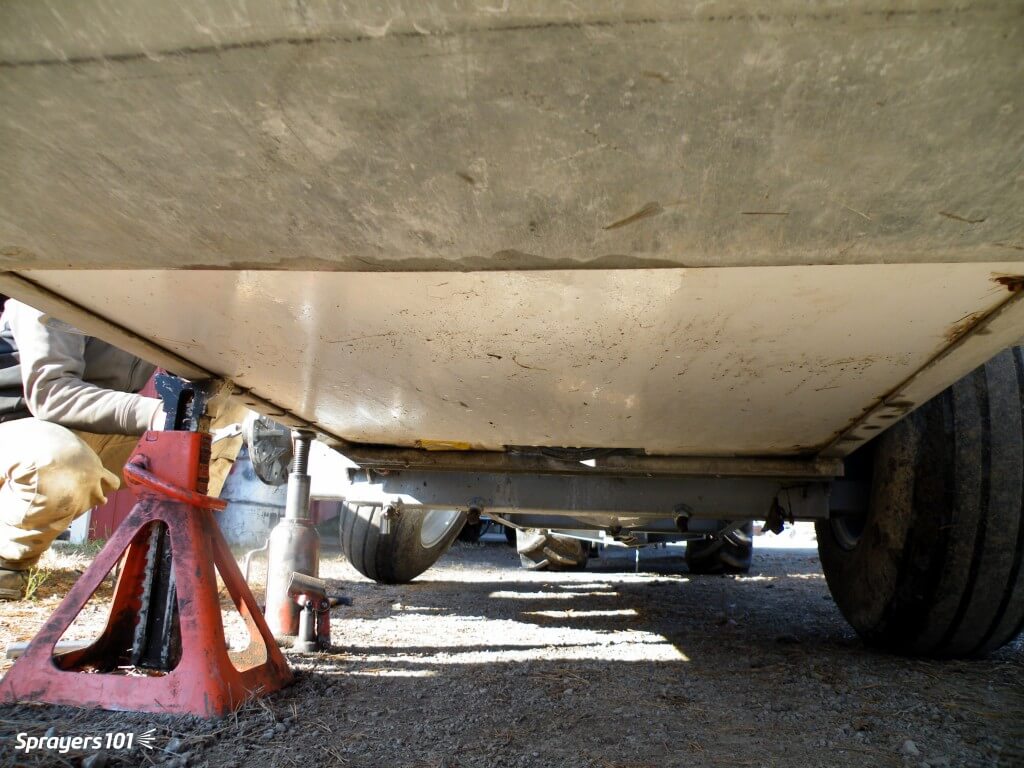
    Empty the sprayer and park it in a well-lit, level spot. Un-hitch the tractor and raise one side of the sprayer using a bottle or floor jack to clear the wheel. Secure the sprayer with a jack stand.

    Raise with one jack, secure with another.
    Raise with one jack, secure with another.

    Step 2

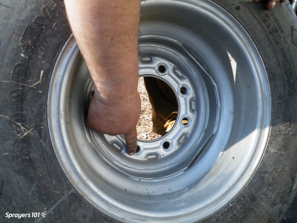
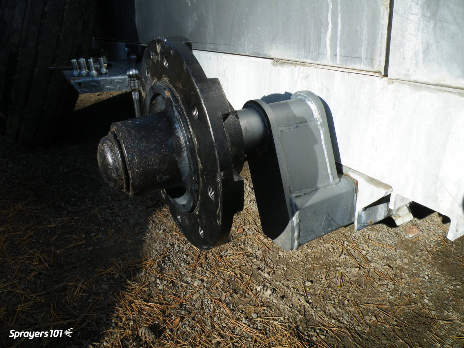
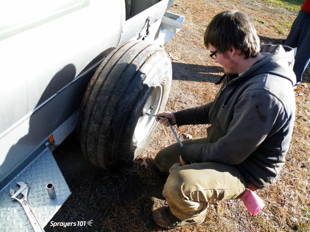
    Remove the lug nuts and take the wheel off the hub. Do not remove the wheel and hub together because it is heavy and you might bang the delicate seal on the spindle. Check the wheel rim for signs of corrosion or distortion (often caused by either loose or over-tightened lug nuts). Check the tread for wear or cuts and check the tire pressure.

    Remove the lug nuts and take the wheel off the hub.
    Remove the lug nuts and take the wheel off the hub.

    Step 3

    Remove the hub cap and pull out the cotter pin. Then remove the nut and washer that hold the hub on the spindle. Put all the small parts in a plastic container with some de-greaser (e.g. Varsol) to clean the parts and keep them from getting lost.

    Remove the nut and washer that hold the hub on the spindle.
    Remove the nut and washer that hold the hub on the spindle.

    Step 4

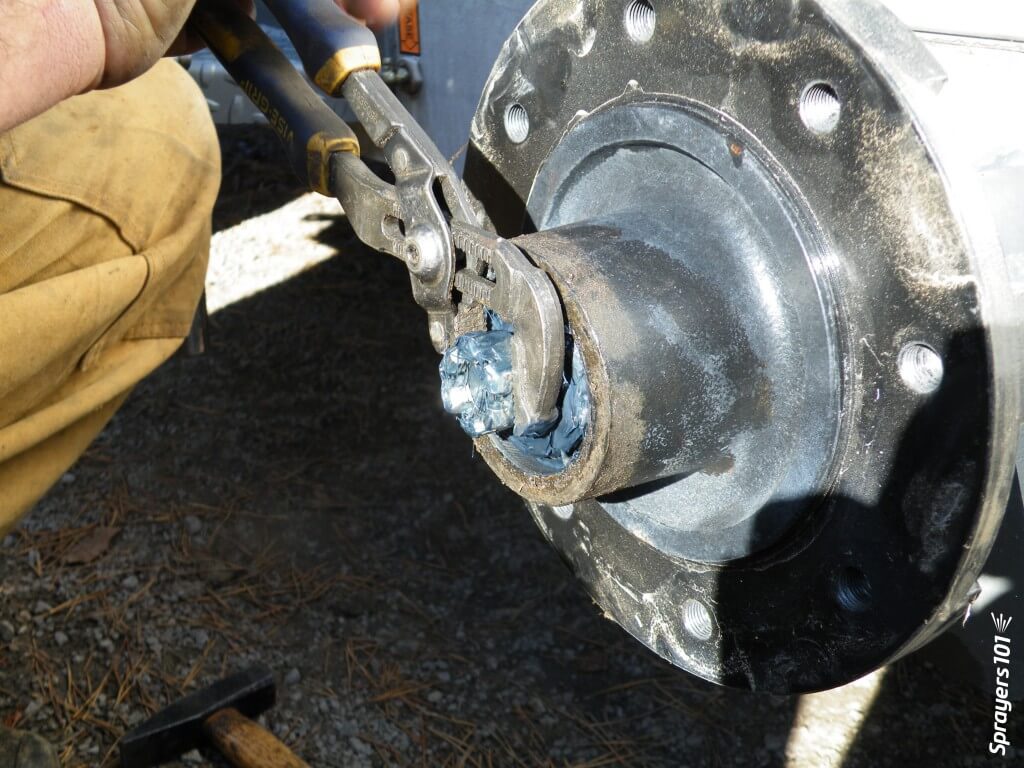
    Knock out the seal and hub bearing and put them in the plastic container. Unless it is damaged, there should be no need to remove the bearing cup (or race) from the hub. The seal is designed to keep dirt out of the assembly, not to keep grease from escaping. Be sure to note which way it is facing. The seal is often ruined during disassembly; have a replacement on hand.

    Knock out the seal and hub bearing.
    Knock out the seal and hub bearing.

    Step 5

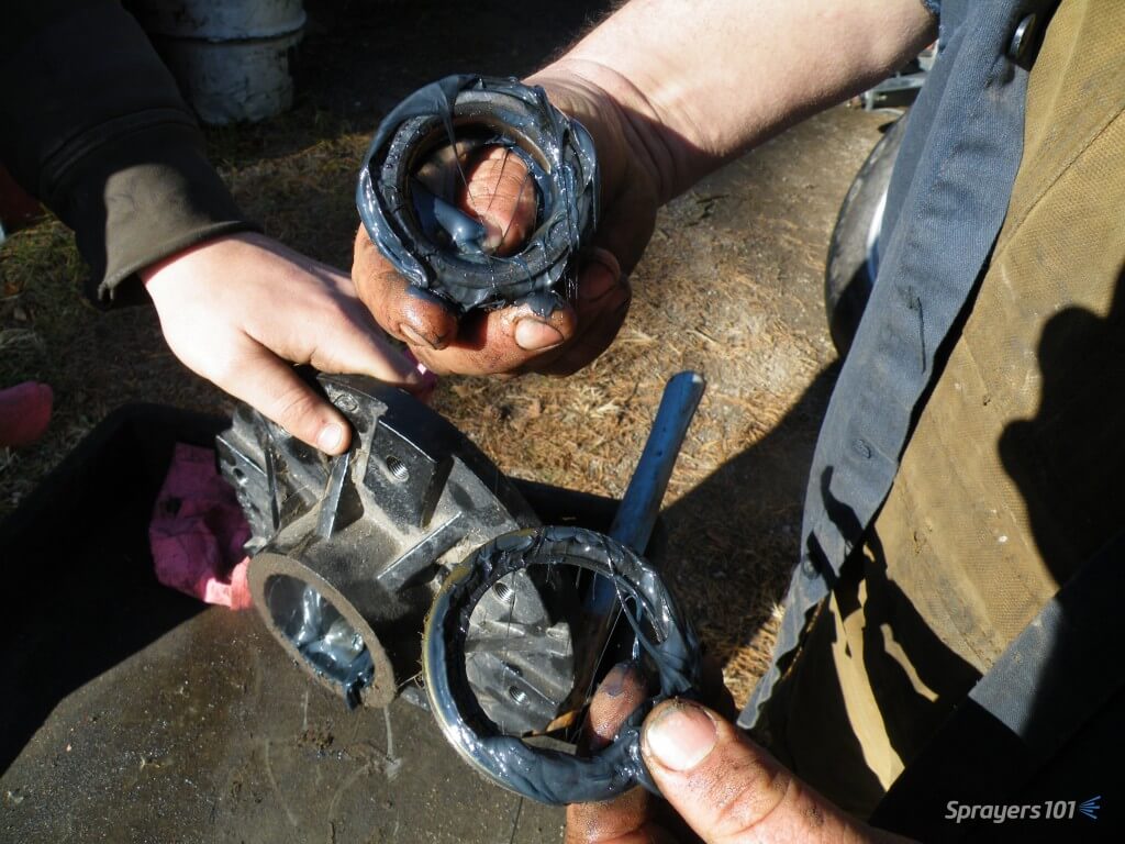
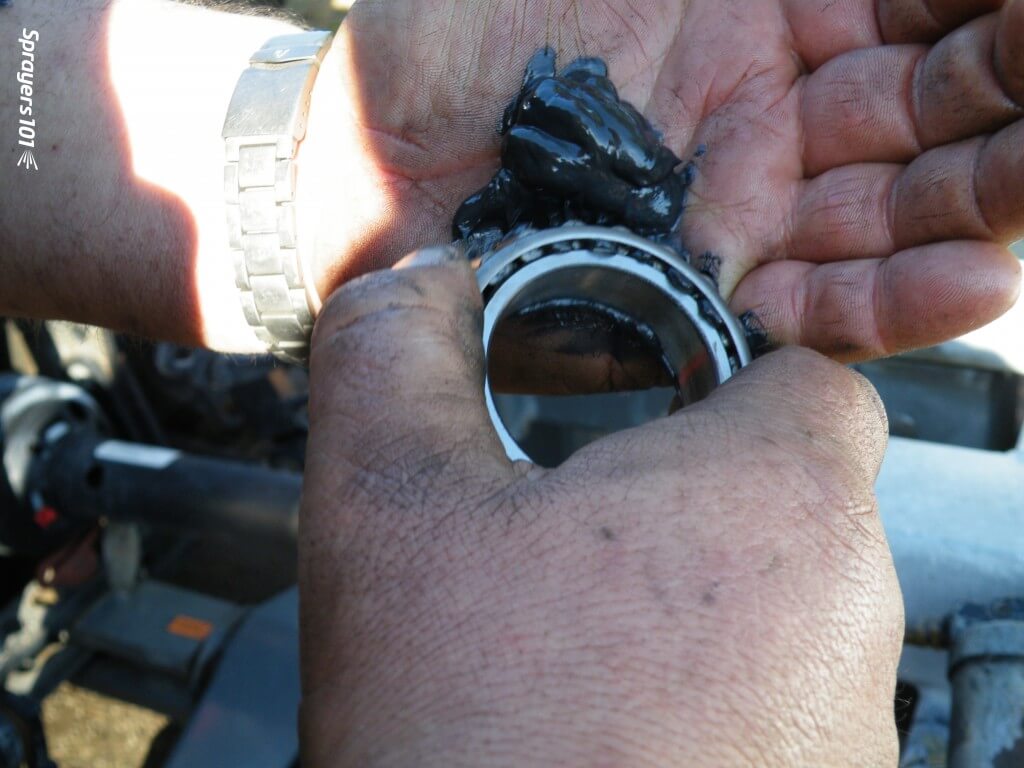
    Clean the old grease out of the hub. This hub has too much and it has filled much of the air space (or cavity) within the hub. That air space is provided so grease is not forced out as the hub heats up, and so dirt is not pulled in as the hub cools. Note the colour of the grease – if it is black and stains your hands, it has burned because too much grease has caused overheating. Look for evidence of dirt or water in the bearing, which indicates seal failure.

    Clean the old grease out of the hub.
    Clean the old grease out of the hub.

    Step 6

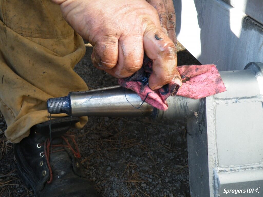
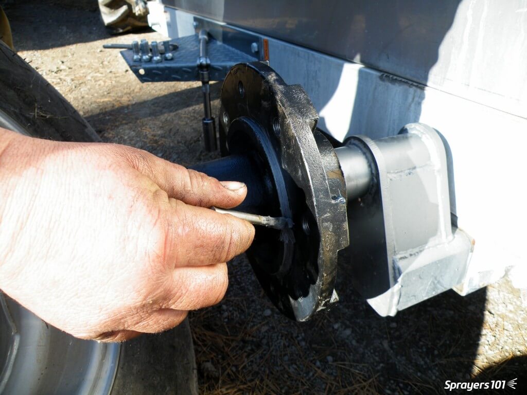
    Wipe dirt from the spindle. Never pressure-wash wheels when they are on the spindles because the spray drives dirt and water past the seal and into the hub. Inspect the sealing surface of the spindle for damage or wear.

    Wipe dirt from the spindle.
    Wipe dirt from the spindle.

    Step 7

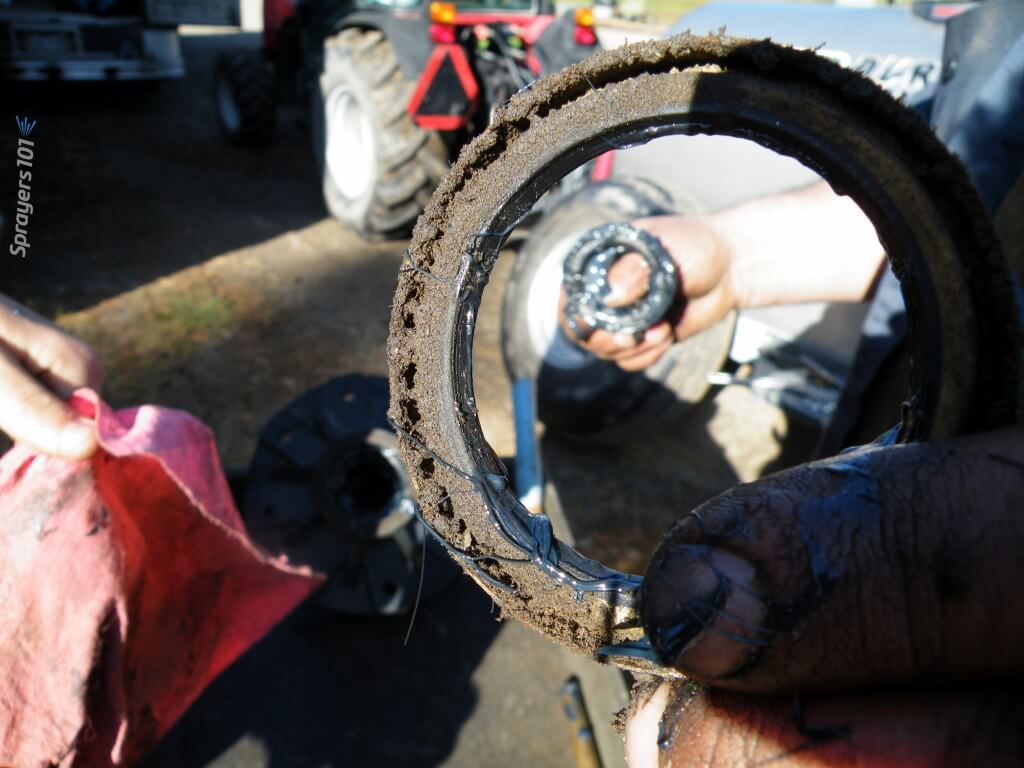
    Clean the seal thoroughly. Seals are easily damaged and may need replacement.

    Clean the seal thoroughly.
    Clean the seal thoroughly.

    Step 8

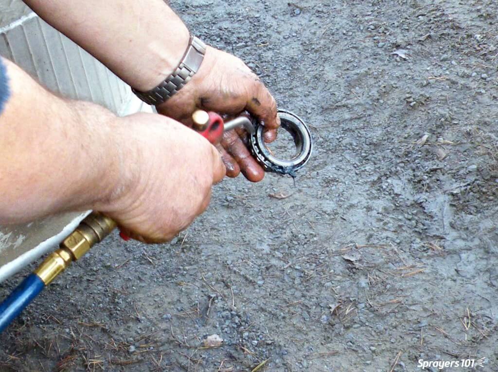
    Clean the hub bearing. Compressed air is a good way to get all the old grease out, but do not spin the bearing with the air.

    Clean the hub bearing.
    Clean the hub bearing.

    Step 9

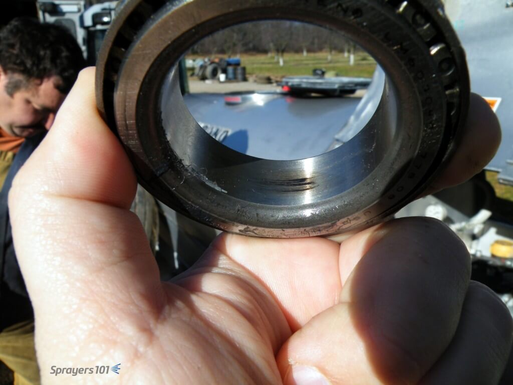
    Look for scratching, pitting or blue metal (indicating heat). This scorch mark indicates the bearing was moving on the spindle, and the friction created heat. Agricultural wheel bearings do not fit tight to the spindles. If there is too much clearance, the bearing race will turn on the spindle where it is not supposed to.

    Look for scratching, pitting or blue metal (indicating heat).
    Look for scratching, pitting or blue metal (indicating heat).

    Step 10

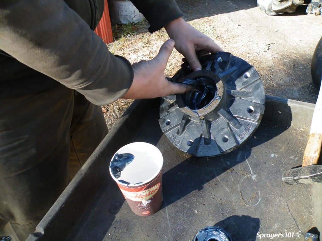
    Repack the bearings, reassemble the hub and re-grease the hub. Bearings should only be ~40% full. Too much grease creates heat and does not let the bearing roll properly. Too little increases friction. No matter which grease you choose to use, never combine greases; they may not be chemically compatible.

    Re-pack and reassemble.
    Re-pack and reassemble.

    Step 11

    Mount the hub tightly on the spindle. Replace the washer, cotter pin, nut and cap. There is no need to bend the arms of a cotter pin all the way back – it weakens the metal. Just bend one arm to 90° and cut off the excess. Use anti-seize on the wheel pilot to make the rim easier to remove next time.

    Mount the hub tightly on the spindle.
    Mount the hub tightly on the spindle.
    Some airblast sprayers (such as this Durand-Wayland) have wheel assemblies that can be rotated to four different positions in the chassis. This will raise or lower the sprayer to better align it with the tractor hitch and PTO shaft.
    Some airblast sprayers (such as this Durand-Wayland) have wheel assemblies that can be rotated to four different positions in the chassis. This will raise or lower the sprayer to better align it with the tractor hitch and PTO shaft.

    Step 12

    Replace the wheel and rim. Do not grease the lug nuts or they might loosen. Over- or under-torqueing lug nuts can cause damage. Look in the manual for your correct torque and consider using a torque wrench. Tighten the nuts in a star-shaped pattern – not sequentially.

    Replace the wheel and rim.
    Replace the wheel and rim.
  • The Droplet Size Debate

    The Droplet Size Debate

    Funny how some issues never go away. For as long as I’ve been in the sprayer business, the question of ideal droplet size for pesticide application has remained a hot topic.  At its root are the basic facts that small droplets provide better coverage, making better use of water, but large droplets drift less.  So why are we still debating this? Because we need both of these properties to be efficient, effective, and environmentally responsible. Ultimately, the droplet size question is reduced into one of values, where everyone’s individual priorities play a role. 

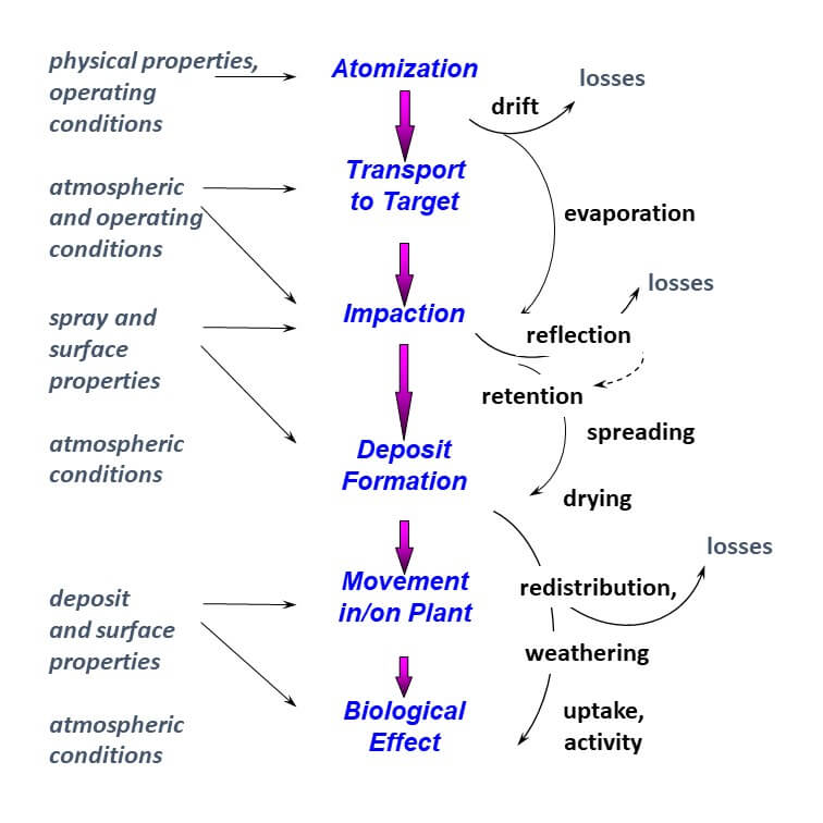
    First, let’s talk about basic principles. To be effective, an active ingredient must make its way from the nozzle to the site of action in the target organism. On the way, it encounters several obstacles as summarized by Brian Young in 1986.

    Figure 1: The dose transfer process of pesticides (after Young, 1986)

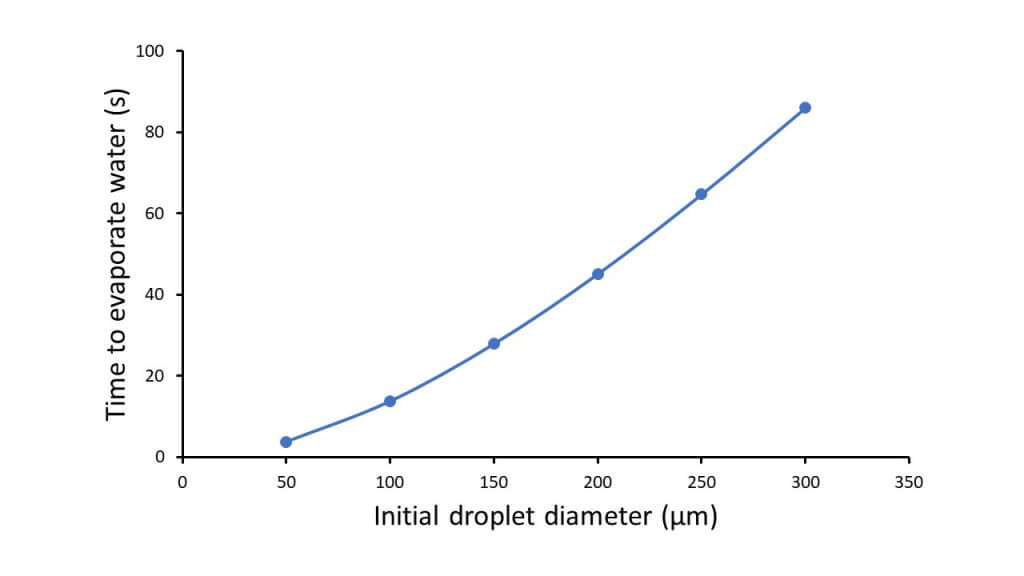
    After atomization and before impaction, the spray encounters two main losses, evaporation and drift. Both of these are more severe for smaller droplets. Smaller droplets have a greater ratio of surface area to volume for any given spray volume, and can evaporate to a much smaller size, even to dryness depending on the formulation, in seconds. For water-soluble formulations, one consequence is lower uptake. Oily formulations may maintain efficacy, but neither type can escape the second effect, spray drift.

    Figure 2: Time to evaporate all water from droplets of various sizes, based on the “two-fluid” model developed by Wanner (1980). Based on 0.8% v/v non-volatile, non-soluble addition, 20 ºC, and 50% RH. This model suggests that final droplet diameter is 20% of initial diameter. Reproduced from Microclimate and Spray Dispersion by Bache and Johnstone (1992, Ellis Horwood Ltd).

    Small droplets are more susceptible to displacement by wind currents due to their small mass. There is no magical size above which drift is no longer possible, but we’ve generally used diameters of 100, 150, or 200 µm as a theoretical cutoff. The proportion of the spray’s volume in droplets smaller than these diameters can be called “drift potential”, and this value is useful to measure the impact of nozzle type, pressure, or formulation on that phenomenon.

    But it’s not quite that simple. Even a small droplet may resist drift if its exposure to wind is limited, perhaps through a protective shield shroud, or lower boom height. Or by increasing its speed through air assist. Higher energy droplets resist displacement.

    These mitigating strategies aren’t lost on sprayer manufacturers who have used them for decades to build lower drift sprayers.

    The next phase of the dose transfer process is interception. The droplet has to encounter its target, but the process is mostly coincidence. Simply put, the target has to be in the way of the droplet’s flight path for the two to meet. Denser canopies are therefore more effectively targeted. A larger number of droplets (smaller droplets or more carrier) also improve the odds. But it’s not that simple. Flight paths can change. That’s where small droplets are more inventive. Because they respond to small air currents, and because such small currents surround most objects, the smaller droplets can weave around objects, following the small eddies generated by air flows. As a result, we’re more likely to find smaller droplets further down in denser, more complex canopies where the eye can’t follow. They simply cascade through.

    Larger droplets, on the other hand, resist displacement by air and travel in straighter lines. They tend to hit the objects they encounter. For that reason, larger droplets are intercepted by the first object they reach and only make their way deeper into a canopy if the path is clear. In other words, vertical, sparser objects allow larger droplets to pass by.

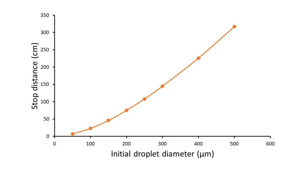
    These properties are related to the droplet’s inertia, and are best described by a parameter known as “stop distance”. Assuming an initial velocity, stop distance is the distance required by a droplet to slow to its terminal velocity.

    Figure 3: Stop distance as a function of droplet size. Assuming a 20 m/s initial velocity (similar to exit velocity of a hydraulic nozzle) and gravity assistance. Note that smaller droplets without the benefit of air assist lose their initial velocity within a few cm of the nozzle exit. Reproduced from Microclimate and Spray Dispersion by Bache and Johnstone (1992, Ellis Horwood Ltd).

    These characteristics, combined with the aerodynamic properties of objects such as tiny insects, cotyledons, leaves, stems, etc. govern the collection efficiency of sprays. Small, slow moving droplets are thus best captured by small objects that don’t create strong enough deflections of airflow to steer the droplets past. Large objects that redirect air around them very effectively are better collectors of the larger or faster droplets whose kinetic energy can guide them through this turbulence. It’s also a matter of probability, as the smaller objects tend to have a lower likelihood of encountering the relatively scarce large droplets of any given spray.

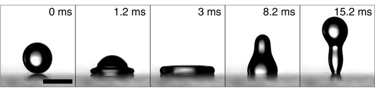
    But once again, that’s not the end of the story. Interception is followed by a critical stage, retention. Objects must be able to hold onto the droplets they intercept. Slow motion video has shown that droplets flatten out on contact with an object as the liquid converts impaction velocity into lateral spread. Once at full extension, the flattened droplets will collapse even beyond their original round shape, pushing them away from the surface and possibly causing rebound. A rebounding droplet may eventually land on target, but that would be a matter of fortune. It’s better if the leaf can offer enough adhesion, diminishing the power of the rebound oscillation, allowing droplet to stick the first time.

    Figure 4: Droplet deformation during impact (C. Hao, et al. 2015. Superhydrophobic-like tunable droplet bouncing on slippery liquid interfaces. Nature Communications. August 2015).

    Small droplets have less mass, and tend to be retained more easily. But more than size is at play here. The morphology and chemistry of the leaf surface is also important, with crystalline or more oily surfaces offering less adhesion for droplets. The physico-chemical properties of the spray mixture becomes important, as characteristics such as dynamic surface tension and visco-elasticity affect spray retention. These properties are optimized through the product formulation effort, and possibly via adjuvants added to the tank.

    We sometimes classify targets as “easy to wet” or “difficult to wet” to summarize these properties. Most grassy plants (foxtails, cereals) are difficult to wet (there are exceptions, such as the sedges) and broadleaf plants vary from the easy to wet pigweeds to the difficult to wet lambsquarters and brassicas. Easy to wet species can retain larger droplets than difficult to wet species, and that’s one reason why finer sprays are preferred for grassy weed control (leaf orientation and size are another).

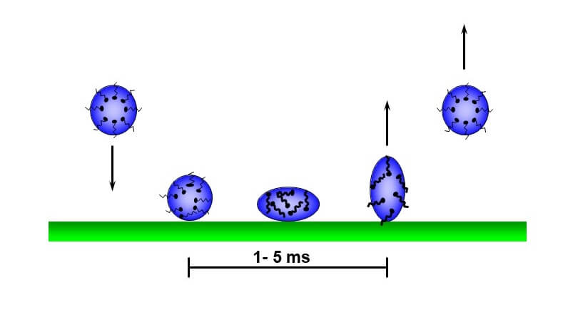
    Figure 5: Droplet deformation, and surfactant molecule alignment, during impaction. The inability of surfactants to reach optimal alignment quickly, and for the target surface to absorb these forces, leads to rebound.

    A few words about surface tension. Although surfactants reduce surface tension and facilitate spreading, this may not be enough to improve spray retention. To be effective, surfactant molecules need to align themselves with the surface of the droplet so they can be a “bridge” at the interface where the droplet meets the target surface. This takes time. The oscillations that occur during impaction continuously create new surfaces, and if surfactant molecules don’t follow suit immediately, the droplet will behave as if no surfactant is present.  Specialists measure “dynamic” surface tension, i.e., the surface tension at young surface ages – a few milliseconds – to better predict spray retention. Very young surface ages have surface tensions of plain water, even with a surfactant present. Only certain surfactants, or higher concentrations of surfactants, can actually improve spray retention.

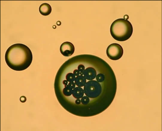
    When air-induced nozzles were introduced in the mid 1990s, one of their claims was the improved spray retention due to air inclusions (bubbles) in the individual droplets. These bubbles made the droplets lighter, and also reduced their internal integrity, promoting breakup on impaction. As a result, the coarser sprays they produced actually had some of the same efficacy performance as the finer sprays they replaced. And indeed, research showed that coarser, air-induced sprays did in fact maintain good performance. Interestingly, performance of non-air-induced coarse sprays used with pulse-width modulation also showed similar robustness of performance. Research comparing air-induced to conventional sprays of similar droplet size rarely showed differences, and when they occurred, they were small in magnitude and could be corrected through improved pattern overlap.

    Figure 6: Air Bubbles in spray droplets (Source: EI Operator. Believed to originate with Silsoe Research Institute, UK)

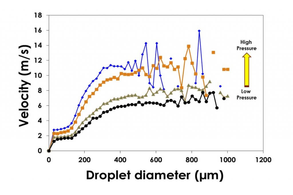
    One reason larger droplets still work well is due to the pre-orifice designs of modern low-drift nozzles. This design reduces the internal pressure of the nozzle itself, with the effect being a slower moving large droplet. This reduced velocity takes away some of the force at impaction, reducing rebound.

    Figure 7: Droplet velocity of larger droplets is reduced by lower pressures from pre-orifice and air-induced design nozzles. Lower velocities reduce droplet rebound.

    Another neat effect of coarser sprays is their ability to entrain air. All sprays move air (simply spray into a bucket to see this), and larger droplets do this better and for longer distances. The entrained air is a form of air assist for the smaller droplets, increasing their average velocity and thus reducing their drift potential while they move in the spray pattern. 

    The final stage of the dose transfer process is deposit formation and biological effect, and that’s where we once again see differences attributable to droplet size.

    Once established on a target surface, the active ingredient usually needs to move to its site of action. In some cases, resting on the surface is sufficient, it depends on the specific product. But for the majority of herbicides, the active ingredient must move across the cuticle into the cytoplasm where it eventually migrates to the enzymes involved in photosynthesis or biosynthesis of fatty- or amino acids.  The cuticle is waxy, with only a few water-loving pathways and the uptake process is basically driven by diffusion and concentration gradients. As such, it is more effective when the product is in solution and the longer the droplet can stay wet, the better.  That’s one reason why spraying during hot, dry days may reduce performance. Again, it depends on the formulation and the mode of action. Too high a concentration can damage membranes, physiologically isolating the active ingredient and reducing its subsequent translocation. It’s always a balancing act.

    If you’ve been keeping track of the score, it’s more or less a tie between large and small droplets. One deposits better and makes more efficient use of lower water volumes, while the other has lower losses from drift and evaporation, helps smaller droplets resist drift, and may improve uptake of some products.

    And this draw is why the venerable hydraulic nozzle has been so successful for so many decades. Hydraulic atomization, by its nature, creates a wide diversity of droplet sizes, ranging from 5 to 2000 µm or greater. As Dr. Ralph Brown of the University of Guelph used to say, this nozzle provides a drop for all seasons. Some small ones for coverage and retention in hard to reach places, and some large ones for uptake and drift-reduction. The result is a robust delivery system that provides reliable results on many different targets under many conditions. In recognition of the heterogeneity of sprays, we don’t refer to specific droplet sizes, but rather their composite, grouped into international categories of Spray Quality such as Medium, Coarse, and Very Coarse.

    Our challenge is to find the spray quality sweet spot, the ideal blend of these contradictory and yet complementary features of our agricultural sprays. And I believe that task is very achievable. Simply put, broadcast agricultural sprays in field crops work reliably when applied as Coarse and Very Coarse sprays in volumes between 7 and 12 US gpa. There is no need to spray any finer than Coarse for good efficacy, as coverage is already sufficient and any additional coverage has small marginal returns. There is, however, value in adding more water when canopies are denser or when leaf area index grows as the crop matures. To gain coverage, adding water is preferred to reducing droplet size because of the value of environmental protection. It so happens that Coarse to Very Coarse sprays provide or exceed the drift protection required by most agricultural labels.

    There is occasional reason for spraying even coarser than what I’ve suggested. It’s certainly required by law for dicamba products on Xtend traited soybeans and cotton, but even then, only in conjunction with higher water volumes to offset losses in droplet numbers.  In practice, moving to Extremely Coarse or Ultra Coarse sprays may allow an application to proceed in higher than average wind without adding drift risk. The use of some additional water is a relatively small price to pay for that additional capability.

    There will always be opportunities for efficacy improvement in specific cases for those willing to spend the extra time to optimize that situation. That’s one of the reasons I’m excited to see the widespread adoption of pulse width modulation (PWM) in the industry, allowing users to change spray pressure and therefore spray quality with no impact on application rate or travel speed. Or the introduction of nozzle switching from the cab, employing the optimal atomizer for a specific situation. Although it remains difficult to define the ideal spray, selecting a spray quality has never been so easy.

  • The Most Important Developments in Spraying

    The Most Important Developments in Spraying

    Some things have improved a lot. Others have lost ground.

    Some years ago, a few of us weed scientists sat around a table and debated the most important developments in agriculture in our lifetimes. It was a great discussion, and we arrived at a few that included direct seeding (for its soil and moisture conservation as well as improved fertilizer placement), GMO crops (for slowing Group 1 and 2 herbicide resistance), and the abandonment of summer fallow in much of western Canada. Let’s apply this exercise to spray application to see what we come up with.

    What follows are my version of the most important spray technology developments in the last 50 years.

    1. Low-drift Nozzles. Spray drift is the biggest time management challenge and also perhaps the biggest public relations battle. These nozzles reduce drift, making more time available for spraying and doing it safely and effectively.
    2. Rate Controllers. I both love and hate these things. On the one hand, a rate controller matches sprayer output to travel speed. On the other, it has allowed spray pressures to go wherever they need, even beyond the optimum, to match travel speed, and that can lead to nozzle performance issues.
    3. Pulse Width Modulation. The pulsing nozzle fixes the rate controller problem mentioned above. Now, travel speed and pressure are independent. Plus, of course, a whole host of other flow management options, such as turn compensation and rate boosting, become available.
    4. Optical Spot Spraying. Once you see these in action, you can’t go back. Why would you spray a whole field when weeds only cover 10% of it? Products like WEEDit and WeedSeeker are proven green-on-brown performers after years of field success around the world.
    5. GPS Guidance. Some of us grew up with foam or disk markers, others learned to aim for brave family members perched on headlands. Achieving accuracy was stressful, overlap was insurance, and misses were common. The importance of this development is probably under-estimated.
    6. Sectional Control. The ability to adjust the spray width in individual nozzle steps makes sense, and this can come with or without PWM. In fact, that alone can save 5% of an annual chemical bill compared to conventional sections measuring about 10 to 15 feet. And it’s definitely better than the left boom or right boom options from the 70 and 80s.
    7. Operator Comfort and Safety. The refuge of the cab makes longer days bearable for all equipment, but for spraying it dramatically improves safety as well.

    But we’re far from done. We still need work in these areas.

    1. Cleaning and Waste Management. I can’t imagine another industry where managing potentially hazardous leftover materials are left to the discretion and circumstances of the applicator. Let’s make it easy and fast to thoroughly clean the sprayer and safely dispose of leftovers. Step 1 is smarter and simpler plumbing.
    2. Boom Stability. Booms are too high, resulting in more drift and poorer nozzle performance, and adding to operator stress. The sole reason is unsatisfactory levelling. It’s possible to solve this, but it seems to not be a priority.
    3. Weight. The road to productivity seems to be paved with larger, heavier machines. The side effects are fuel consumption, compaction, getting stuck. Let’s get smarter with frame design and logistics and talk acres/h rather than tank capacity and power.
    4. Cost. All farm equipment has seen cost increases that far outstrip inflation or any reasonable accounting of productivity and features. Sprayers lead the way. Yes, it’s possible to spins this as a value proposition. But it shouldn’t be necessary.
    5. Drift Management. Sprayer design continues to ignore drift management. We need sprayers that produce less drift by design, and this requires consideration of tractor unit, wheel, and boom aerodynamics. It’s more than a droplet size issue.
    6. Direct Injection. Although very handy for single product application, the plethora of product formulations and mixes has limited the success of direct injection systems. The complexity of injecting at the nozzle, and the resulting lack of available systems, has stymied some very attractive options, such as site-specific rate or product use.
    7. Ergonomics. If you need training, or to call someone before using your new sprayer for the first time, something’s wrong. Interfaces need to be intuitive and simple. The golden age of spray monitors was the 1980s. Those featured a main power toggle switch, a pump power switch, boom section switches, an agitation switch, and a simple way to enter the important information which was basically desired application volume. The screen can still be pretty, and you can still paint and monitor or tweak all the functions if you like that. But let’s at least have different tiers so beginners can also use the machine. Make interfaces using the philosophy Steve Jobs instilled in his trusted designer Jony Ive with the first iPod: no more than three clicks to achieve any desired outcome.

    A few areas show promise and may suit certain niches.

    1. In-Crop Weed Sensing. The green-on-green sensing that has been made possible by machine learning has shown some encouraging early success. Continuing improvements will eventually bring its reliability to within commercially acceptable standards. There is significant activity below the radar in this area, as all players recognize the enormous upside of a breakthrough.
    2. Autonomy. While dispensing a pesticide adjacent to sensitive areas isn’t exactly the low-hanging fruit of autonomy, such field sprayers will have a fit in the temperate plains of North and South America, Australia, and Asia and may help solve the cost and weight problem.
    3. Drone Application. The rapid pace of advancement in remotely piloted aerial systems, along with a seemingly low barrier to entry of new companies, will put pressure on the industry to make a decision on this alternate application method. If it can be done safely, it will have a dramatic impact.

    If you want to improve your sprayer, don’t ignore the small things you can do in your operation. Although we’re conditioned to look for game-changing technology, the most sustained improvements don’t come from a single innovation, but from a period of persistent evolution. A lot of small improvements add up. Spray application is no different.

  • Don’t try this tempting shortcut

    Don’t try this tempting shortcut

    There’s a call that I’ve been getting for 20 years now. It came again this week. Someone has a twincap with two small air-induced tips, and they’re applying herbicides and fungicides with low water volumes, often 5 gpa, sometimes less. They call because they want to know how much wind they can spray in. Is 30 km/h OK? They want my blessing.

    I don’t need to hear much more. Some nozzles are sold entirely on the premise that they provide superior coverage – more droplets per square inch – and that this improved coverage permits the reduction of water volumes. Furthermore, the claim goes, when water is reduced, the spray concentration increases and the whole darn package just works a lot faster and better.

    This line of thinking is as old as spraying itself. Applicators seek pesticide performance as well as productivity, and this approach gives them both. The proponents are well aware of their customers’ desires, and sell into it. “Use these tips and cut back on water. Any more than this just runs off anyways. You’ll get better coverage and better performance, get more spraying done.” It’s a convincing argument. Get an edge on your neighbour, the person who’s not in on the secret and is wasting time and water.

    Why don’t I embrace it? There are a few reasons.

    First, it doesn’t tell the whole story. Invariably it involves a twin nozzle setup. Use two nozzles, get more droplets, right? If that were true, believe me, I’d be advocating for quintuples.

    Fact is that the only factors that change droplet numbers are droplet size (spray quality) and water volume. Want more droplets at the same water volume? Make the spray finer. Want to keep spray quality and add droplets? Add water (not nozzles).

    The easiest way to improve coverage at the same volume is to use a finer nozzle, or to increase spray pressure. Depending on how far you go, you could make the spray finer and cut water, and still have more droplets per square inch.

    The hardest way to improve coverage is to purchase a twincap and buy two nozzles, each of them half the size. True, within any given nozzle type, smaller sized tips usually generate finer sprays. But why bother with two tips? They’re more expensive and plug more.

    If someone asks me how to improve coverage without changing water volume, I usually tell them to speed up a few mph. The rate controller will increase pressure and the spray gets finer. If speeding up is not possible, get one size smaller nozzle and run at higher pressure, same speed. Or keep nozzle and speed, and add some gpa, pressure will go up. It’s that easy. No twins necessary.

    Second, the twin nozzle/low volume approach exaggerates the value of the twin nozzle for herbicides. With small plants and relatively open canopies in the early season, plus our high booms and travel speeds, the twin tips are not adding a lot, if anything at all, to coverage. It remains a sum of droplet size and water volume, the angle is not important at this stage. Deposit is by turbulence and wind, most of the time.

    Third, low volume believers ignore a few potential problems. Drift is a big one. Low volume, fine spray operators are surrounded by nervous neighbours. They have fewer hours per day during which drift is acceptably low. And they definitely should not be on the field when wind is at 30 km/h. Basically, they’re a bit uncomfortable (at least they should be) and get less done per day.

    Another potential problem is evaporation. Most sprays, even when applied at lower volumes, are still 90% or more water. The same volume of water evaporates much quicker when atomized into smaller droplets. This has two main downsides: On their way to the canopy, small droplets evaporate and become even more drift prone, and may not impact at all. Those that impact evaporate shortly thereafter. Research has shown that pesticide uptake is better from wet than dry deposits.

    When Delta T (dry bulb minus wet bulb temperature) is high, evaporation can be so strong that it reduces pesticide performance or causes solvent burn. Fine sprays make it worse.

    I also hear about the use of oily adjuvants to control evaporation from small droplets. This could be even more dangerous. Small droplets drift, and evaporation to dryness is actually helpful in reducing the impact of that drift. How? It makes the small droplets disappear, with their remnants dispersing into the turbulent atmosphere. With oily adjuvants, the small droplets stick around and stay potent and their drift damage is much worse.

    Lastly, the practice is possibly off label. Water volume and spray quality label statements are designed to offer good performance and acceptable drift risk. While that part of the label is often a bit dated, it does provide better support from the manufacturer should something go wrong.

    If you’re spraying under hot, dry and windy conditions, the low volume, fine spray approach is irresponsible. Use sufficient water (7 to 12 gpa) to allow low-drift sprays, at least Coarse to Very Coarse, in some case, even coarser.

    Agronomists provide the best possible information for their clients, based on scientific evidence and experience and in accordance with their professional code of ethics. Sometimes the news we deliver aren’t what the customer wants to hear. But we have to represent the interests of all of us, collectively. I find that pretty important.