“What is the right way to apply this pesticide?” It’s one of the classic questions. Applicators know that spray method determines the efficacy of the application as well as its environmental impact. And it has to use time and water resources efficiently to make sense.
To answer the question properly, we need to take things one step at a time.
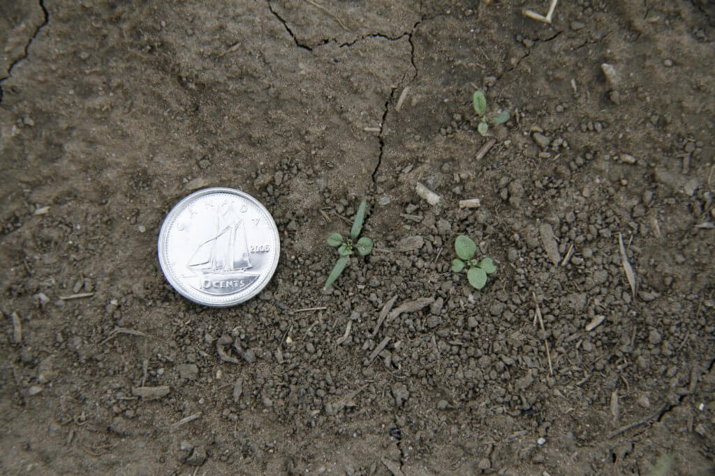
Canopy: To start, we need to look at the canopy that our application will go into. If it’s an early season spray into a seedling crop, then the canopy won’t be much of a barrier. Lower water volumes can be possible. Droplet size will only depend on the target type and the pesticide mode of action.
Small weeds require more smaller droplets to secure effective targetting
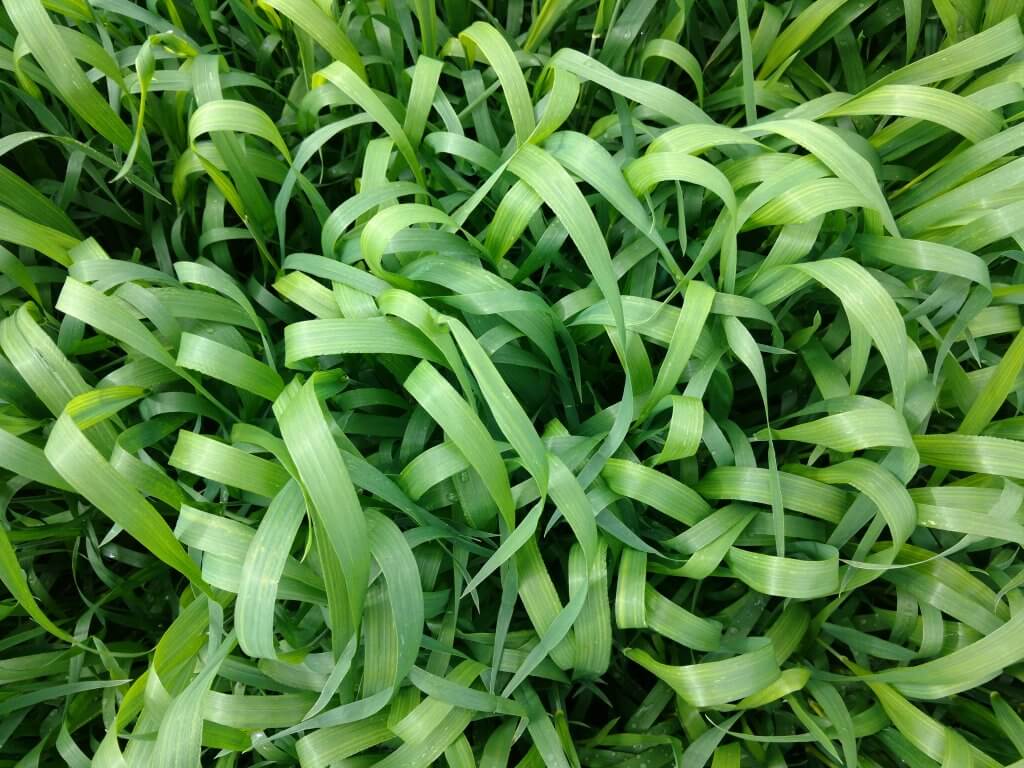
If it’s a later application into the bottom of a maturing canopy, the foliage may intercept the spray before it reaches the target area. More water will likely be needed, and droplet size may become more critical for getting the spray to its destination. Dense canopies are a real challenge and lower-canopy deposition usually benefits from finer sprays because the small droplets can turn corners better.
Dense canopies are very difficult for a spray to penetrate. Higher water volumes and smaller droplets are the key tools that help.
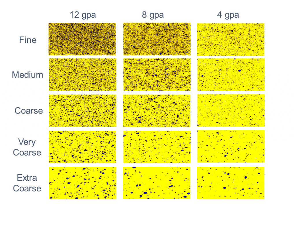
2. Water Volume: Regardless of canopy, the range of application possibilities will depend on the water volume and spray quality combination. It’s math: assuming some constant amount of coverage on each leaf, more layers of foliage will require more water. Using less water volume will make it necessary to use finer sprays to keep droplet numbers constant. More water will allow coarser sprays. This decision has implications for drift, and by extension, affects the number of hours we can spray in a day. More drift tolerance means better application timing and overall productivity.
The tradeoffs between water volumes and droplet sizes are seen in this figure. Once a certain threshold of coverage has been reached, a further increase in coverage may not provide any additional control.
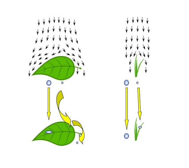
3. Target Type and Droplet Behaviour: Whatever spray we use, the target plant or insect needs to intercept, collect, and retain the spray droplet. This is where the fun begins. Target leaves may be vertical or horizontal, large or small. Their waxy surface may be easy-to-wet or difficult-to-wet. The general rules of thumb are that larger, more horizontal and easy-to-wet surfaces are better suited for coarser sprays – these are intercepted more efficiently and stick readily. That is a reason why most broadleaf weeds and crops are very compatible with low-drift sprays.
Large targets (left) are most efficient at intercepting larger droplets (provided droplet bounce is not a problem) because smaller droplets may evade capture. Smaller targets are usually missed by larger droplets but are very capable of capturing smaller droplets.
On the other hand, smaller, vertically oriented and difficult-to-wet plants require finer sprays for effective targetting. Larger drops tend to miss these targets or bounce off them. Most grassy, and some broadleaf weeds (especially at early growth stages) fall into this category.
4. Mode of Action: There are nearly 30 modes of action on the herbicide world, and another ten modes for insecticides and fifteen for fungicides. The effect of droplet size and water volume on their uptake and translocation varies, and it’s probably not correct to generalize too much. There is one notable product, glyphosate. For this product, research has consistently shown that large droplets and more concentrated mixtures provide better uptake. But we’ve also seen problems when this is over-done, causing localized toxicity and limiting translocation.
With many products, we’ve sometimes seen better performance with finer sprays due to improved coverage, yet at other times less performance due to rapid evaporation. On the whole, it’s probably still fair to say that contact modes of action require finer sprays and higher water volumes, even if there is the occasional exception. And systemic products can typically handle coarser sprays. We’ve always been surprised just how coarse we seem to be able to push the system before any loss of efficacy.
What does it all mean? In spraying, we need to accommodate a lot of diversity. The average application is broad-spectrum, targeting large and small broadleaf and grassy plants. Many sprays are tank mixes of several modes of action. It’s impossible to prescribe a specific spray for each situation. We need a little bit of everything. And the spray should not be drift-prone. It’s easy to see that we need to aim for the middle to accommodate everything.
The traditional flat fan nozzle, either in its conventional or low-drift form, generates a wide range of droplet sizes that can range from 5 µm to about 2000 µm. If we need fine droplets, they’re there. If we need larger droplets, they’re also there. The proportion of the total spray volume in each specific size fraction depends on the nozzle choice and size, the spray pressure, and the adjuvant mix in the tank. Overall, the system is very robust, and although it requires some tweaking, a well chosen average spray can achieve most tasks well enough.
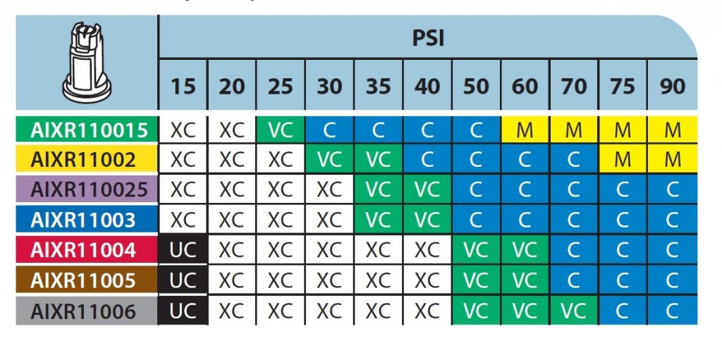
A typical spray quality chart shows the expected spray quality for a range of nozzle sizes and pressures. Spray quality measurements follow standards set by the ISO and ASABE, these change from time to time and therefore charts tend to become outdated.
Our research has repeatedly shown that a Coarse spray is a good starting point that does most things well. It is acceptable to move into a Very Coarse or coarser category provided water volumes are also raised, and provided the target types and modes of action are suited for this change.
It is rarely necessary to spray finer than Coarse, and when this is done, we recommend against spraying finer than a Medium spray. There is simply no advantage from product performance, and drift risk becomes unacceptable.
Tweaking the System. In order to maximize the performance of your spray, and the efficiency of your overall spray program, here is some advice:
Know the spray quality of your nozzles, and their response to spray pressure. Manufacturers publish this information in their catalogues and on-line. Make this your homework assignment.
Use the coarsest spray that you can afford to. This will make the application safer, it will widen the weather window, and it will simply let you get more done in a day or a season. Coarse sprays work.
Use spray pressure and water volume to fine tune the application for a specific purpose. If using a contact product, you can keep the same nozzle you used for a systemic product. Apply more water or use more spray pressure to generate more droplets.
Do not skimp on water. Higher water volumes tend to make an application more uniform, robust, and crop-safe. Spray coverage improves. Canopy penetration improves. Coarser sprays are possible. The only exception to this rule is glyphosate, which works better in lower water volumes. But with higher glyphosate rates and more tank mixing, even that exception is disappearing.
Learn as much as you can about how your pesticides work and where they need to be in your canopy. Apply your knowledge to select optimal water volumes and spray qualities.
Be wary of people who advise very low water volumes in conjunction with fine sprays. They want to appeal to your need for efficiency, but do so at the cost of consistency and environmental stewardship. Plus these types of applications are illegal for many of our products.
I was recently asked to describe Pulse Width Modulation to a non-farming audience. My instinct was to send them back to what we’d already written about the topic on Sprayers101, here and here. But on reviewing the material, I soon realized that most of our posts assume a certain amount of basic knowledge and understanding. What about people who are new to the business, or just curious? Not that helpful.
This is the first in a series of articles that cover off topics which may be too basic for many, but are nonetheless important for others. More to come. And suggestions welcome.
Sprayers are used to apply crop protection agents to fields, and as with all crop inputs, it’s important to apply the correct dose. For boom sprayers, dose is a product of the swath width, the sprayer travel speed, and the flow rate of spray liquid through the nozzles. Of these three factors, swath width is taken as constant, whereas travel speed and flow rate are variable. If travel speed changes, flow rate also needs to change to maintain the target application rate.
The vast majority of nozzles come in fixed sizes. As a consequence, the only way to change their flow is with spray pressure. In a modern sprayer, a computer known as a rate controller takes care of the math and the adjustments. For example, if the sprayer speeds up, it will need to deliver more liquid to keep the same application volume per acre. The rate controller knows the swath width (entered by the user) and senses travel speed (using radar or gps) and liquid flow rate (using a flow meter). If the travel speed increases, the rate controller causes the spray pressure to increase until the flow rate sensor shows that the flow is enough to maintain the target application rate.
The problem with this approach is that sprayer nozzles are very sensitive to spray pressure. Too low a pressure will cause the spray pattern to deteriorate, resulting in poor coverage. Too high and the spray will become too fine, creating drift problems. As a result, traditional sprayer operators have to stay within a very specific, narrow speed range. This may not always be possible if, for example, the terrain is hilly or the soil is wet.
One solution to this problem is to control flow rate differently. A fairly new way to do it is with Pulse-Width Modulation (PWM). This is a fancy term that describes a well established way that liquid flow rates are controlled in a number of other tasks such as fuel injection or hydraulic oil systems.
With PWM, each nozzle body is equipped with an electronic solenoid (shut-off valve). The valve turns on and off ten or more times every second, creating an intermittent, pulsed spray. The number of times the valve cycles on and off per second is called the frequency, measured in Hertz (Hz), cycles per second. The proportion of time that the valve is open, called the pulse width or duty cycle, is related to the liquid flow rate passing through the nozzle. Duty cycle can be electronically controlled.
For example, each nozzle can operate at its full rated flow (100% duty cycle) or a fraction of its flow (say 20% duty cycle). At low frequencies (about 10 to 15 Hz, common in PWM systems) duty cycle is proportional to the flow rate of the nozzle. At 20% duty cycle, the nozzle delivers about one fifth of the flow compared to 100%. The pulses are so quick that it doesn’t affect overall coverage or droplet size. With this system, as a sprayer speeds up or slows down, the duty cycle changes automatically to match the flow rate requirements calculated by the rate controller.
What does this mean in practice? For one, the sprayer no longer relies on a pressure change to influence the nozzle flow rate because duty cycle has taken over that job. In fact, the operator can set the pressure to whatever is necessary for best coverage or best drift control, whatever is most important. A change in travel speed caused by a hill or a slippery spot doesn’t affect pressure any more. The end result is a spray application that is not only more accurate, but also more consistent over varying conditions.
Drift control is easier with a PWM system. A common way to reduce drift is to make the spray coarser, and this can be achieved with lower spray pressure. But lowering the pressure results in less liquid flow, and the operator has to slow the sprayer down if the same application rate is to be maintained. With a PWM system, the operator simply lowers the pressure. The system makes up for the lower flow by internally increasing duty cycle, allowing the same travel speed to continue and therefore not affecting the work rate.
An added side benefit with a PWM system is that it provides opportunities for site-specific management of application rates. Parts of the field needing less or more product can receive what they need. All the operator does is change the rate, via duty cycle, according to a prescription map.
A further bonus is the highly resolved sectional control that can be achieved. With any wide agricultural implement, overlaps are inevitable. With an advanced version of a PWM system, individual nozzle solenoids can be shut off or turned back on as required, thereby preventing double applications at these overlaps.
In short, PWM systems give operators much more control over their spray operation. And that’s good for everybody.
Not being able to finish a tank due to weather or any other reason happens to just about everyone. Is it OK to simply leave the sprayer as is, and resume spraying later after some agitation?
In many cases, the answer is yes. Most pesticide mixtures are stable in short term storage. On resuming spraying, an agitation could be all that’s needed to get back to where you started a day or so earlier.
But there are three important exceptions.
When the active ingredient is formulated as a suspension. Suspensions are typically wettable powders and flowables, and rely on a clay carrier to distribute the active in the tank. Because clay is denser than water, these formulations settle out quickly after agitation stops. Sure, they can be brought back into suspension with vigorous agitation. But in lines and booms, boom ends and screens, dislodging a settled clay carrier is much more difficult. It’s also hard to tell if the cleaning has been successful because the problem spots are hidden.
The best solution is to flush the spray boom with water before materials can settle and lodge. A visual inspection where access is possible, such as strainer bowls and boom ends, is part of the process to ensure the formulated product has been removed.
Learn to identify which formulations are suspensions. There’s lots of jargon out there. Look for terms such as DC, DF, DG, DS, F, Gr, SP. Even EC formulations are suspensions (oil in water) and require agitation.
When the active ingredient is chemically unstable. Some pesticides can degrade in the tank, usually due to alkaline (high pH) hydrolysis. The effect is very pesticide specific, but in general, insecticides (particularly organophosphates and carbamates) are more susceptible than other pesticides. This fact sheet by Michigan State University describes the impact of pH on a the half-life of a large number of pesticides.
Note that in the examples in the MSU fact sheets, pesticide half lives are typically days and weeks, and only rarely hours. Also note that while high pH is most often problematic, low pH can lead to faster breakdown in a small number of products.
Ensuring tank mix stability requires a pH meter or paper, and possibly a pH modifier such as citric acid. But do your research first! Here’s an article on pH and water quality.
When the tank previously contained a product known to harm the current crop. This situation is most common and most difficult to address. Some examples from western Canada are Group 2 modes of action sprayed prior to a canola crop. Why are Group 2 products implicated? Many are formulated as dry products on a clay base, and these can settle in boom ends, adhere to tank walls, or get stuck on screens. Their solubility is pH dependent, as we explain in this article.
Canola is particularly sensitive to this mode of action, and the most common canola herbicides, Liberty and glyphosate, are formulated with strong detergents that act as tank cleaners.
Even when applicators think that their tank is clean, they can’t actually be sure and can’t do much about it at that stage. The stripping of tiny amounts of residue off the tank walls, filter screens, or plumbing, can happen during a mid-day stop or an overnight break. Applicators eventually find out that this happened, usually about two weeks after spraying.
Our advice is:
After spraying a herbicide to which a subsequent crop may be sensitive, with the classic case being a Group 2 and moving to canola, be extra diligent with cleaning and pay attention to the tank walls, all screens, and boom ends.
The best way to solve issues is to avoid them in the first place. If the weather looks unsettled and may interrupt your spray operation, consider mixing smaller batches that can be sprayed out completely even if conditions change quickly. This allows you to rinse the tank and spray water through the boom, thus avoiding a contamination problem developing overnight.
If that’s not possible, at least do not let a tank mix sit in the boom overnight. Instead, use your clean water tank to push water through the boom prior to storage and double check the screens. The following day, prime the boom with your tank mix as usual and resume spraying the crop.
If you’re not sure that your sprayer can draw from the clean water tank and push through the booms (the wash-down nozzles are, after all, the intended destination for that water), decipher your system and add the necessary valves that make this possible.
A useful design that helps flush and prime a boom quickly is the recirculating boom offered by some aftermarket boom manufacturers. These booms are also more common on European sprayers. A nice feature of such designs is that the tank contents can be pumped through the entire boom assembly without actually spraying. This ensures that the boom is primed without any soil contamination. It also dilutes whatever residue there may be in the boom plumbing with the entire tank, likely reducing its concentration enough to be of little concern.
An additional feature of recirculating booms is that many offer stainless steel tubing throughout most of their feed and return length, minimizing the black rubber hose products that often adsorb, and later release, herbicide contamination.
Even if a wholesale boom or sprayer change is impractical, consider switching to steel boom lines and tanks tank to minimize residue carryover.
As is often the case in the spraying business, prevention is easier and less costly than solving a big problem later. Spray mix storage is one of those examples where a small amount of extra effort at the beginning can pay big dividends later.
Low drift nozzles have become the standard way to apply pesticides from a boom sprayer. In order to use them properly, we need to understand how they are designed and how they are intended to work.
Sprayer nozzles have three functions on a sprayer.
Metering flow
Atomizing liquid
Distributing liquid uniformly
Accurate metering of the flow is done through precise machining or molding of the nozzle.
Atomization of a liquid occurs by imposing some sort of force on the liquid that causes it to break up from a stream or a sheet into droplets of the desired spray quality.
Distribution is done by generating a pattern that, in combination with adjacent nozzles, produces similar dosages in appropriate droplet sizes and densities, along the target area.
All three of these functions are confirmed by the nozzle manufacturer, but the properties are likely to change with wear.
Atomization
Atomization forces could be air-shear (used in some aircraft, airblast, or twin-fluid nozzles), centrifugal energy (used in rotary atomizers), electrical energy (used in some electrostatic sprayers), or hydraulic pressure (used in the most common nozzles, the flat fan or hollow-cone tips).
Typically, the higher the applied energy, the greater the break-up of the spray. More air-shear resulting from faster aircraft or fan speeds, faster rotation of a cage, or more hydraulic pressure all have similar effects: they create finer sprays.
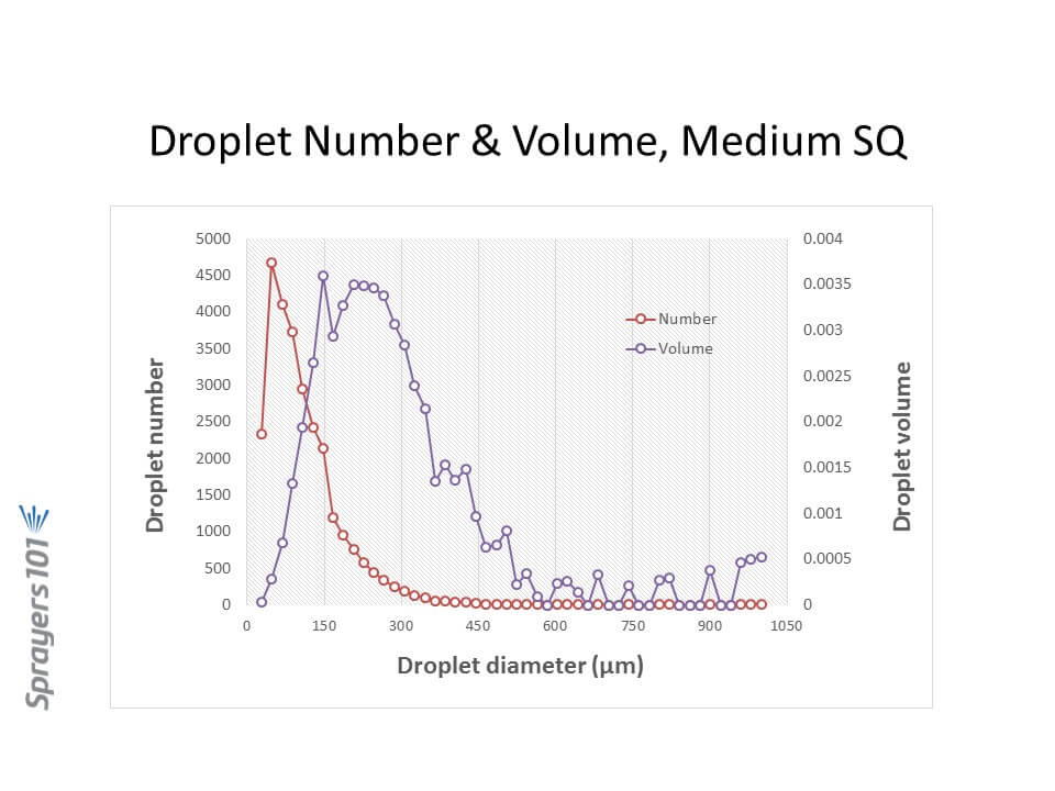
Most nozzles produce polydisperse sprays, comprised of a large number of different droplet sizes. For hydraulic flat fan nozzles, droplets ranging from 5 to 2000 µm can be produced. The exact distribution of the volume in these droplet sizes depends on the nozzle design, the spray liquid, and the pressure. Here are three examples, representing approximately Medium, Coarse, and Extremely Coarse sprays.
Droplet size distribution by number and volume from a Medium spray. Note the majority of the droplets are small, but the majority of the volume (dose) is in somewhat larger droplets.
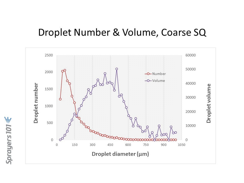
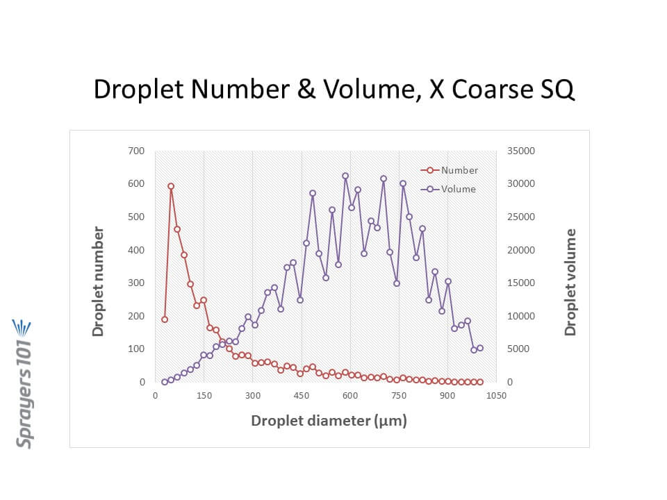
Droplet size distribution by number and volume from a Coarse spray. Like in the Medium spray, the majority of the droplets are small although there is fewer of them. The majority of the volume is in intermediate sized droplets.
Droplet size distribution by number and volume from a Very Coarse spray. While the majority of the droplets are small as in the finer sprays, their overall number is sharply reduced from the finer sprays. The volume is now in the largest droplet sizes.
Let’s focus on hydraulic nozzles, by far the most common in agriculture.
Spray Pressure
Spray pressure is a useful tool for controlling droplet size from any hydraulic nozzle. Need a finer spray? Add pressure. It is also the basis for the age-old recommendation that lower pressures are a good tool for reducing drift.
We impose practical limits on the upper and lower range of recommended pressures based on several other factors, chief among them the spray pattern.
Spray patterns of a certain width, or angle, are required for proper pattern overlap. The convention is to space hydraulic nozzles at 15 or 20 inch intervals along a boom, and operate them at about 20” above the target. Boom height values will depend on the fan angle of the nozzle and the degree of overlap required. For low-drift flat fan tips, a minimum 100% overlap is best. With 100% overlap, the spray pattern width at target height is twice the nozzle spacing. With this approach, at any point under the boom, the target receives droplets from the closest two nozzle patterns.
Pattern angles are published by manufacturers, but in practice, angles often differ from those values and can vary with spray formulation. Importantly, they tend to become narrower at lower pressures. The exact pressure at which this happens depends on the tip design, but experience shows that pressures below 20 psi for conventional nozzles, and 30 to 40 psi for low-drift nozzles, result in poor (too narrow) patterns. Narrow patterns reduce overlap, resulting in poor distribution.
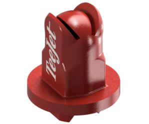
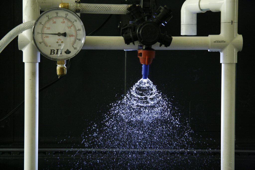
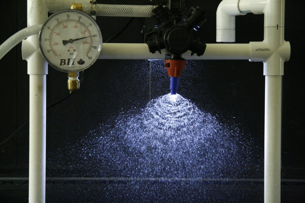
TeeJet AI11003 at 20 psiTeeJet AI 11003 at 80 psi
We might also limit pressures at the upper end, based on drift potential. Most conventional flat fan nozzles, for example, drift excessively at pressures above 60 psi or so, hence that limit.
Low Drift Nozzles
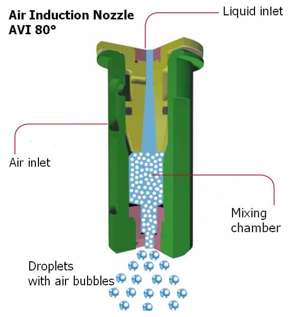
Low drift nozzles were quickly adopted by applicators due to their ability to reduce drift and thereby widen the window of safe spray application. They work by using a two-stage design (often called “pre-orifice”) to reduce the internal operating pressure of the tip. The pre-orifice, the original liquid inlet, is round and sized for the nominal flow of the tip. The exit orifice is eliptical in shape and has a larger flow capacity than the pre-orifice, by about 1.2-fold to 2.5-fold. The larger exit creates an internal pressure drop, so the pattern formation produces larger droplets as though the operating pressure had been reduced. Most modern low-drift tips also introduce air into the nozzle via a built-in venturi. This further suppresses the formation of driftable droplets and introduces air into the interior of the nozzle, adding some pressure back to the system.. The Albuz AVI nozzle schematic below explains the venturi design.
Cross-section of the Albuz AVI venturi nozzle.
The tapered channel inside the nozzle is a venturi, which draws air into the nozzle via integrated ports. When low-drift nozzles are operated beside conventional nozzles at the same pressure, low-drift nozzles produce much fewer driftable fines, and also more larger droplets.
But while the two-stage design is useful for managing drift, it also conceals the actual operating pressure of the exit orifice in these tips. The exit orifice is important – it is the part of the nozzle that does the atomizing and that forms the pattern.
Let’s illustrate the pressure inside a low-drift tip by operating an air-induced low-drift nozzle at 60 psi. This nozzle has a pre-orifice size of 03 (0.3 US gpm at 40 psi, blue) and an exit orifice size of 06 (0.6 US gpm at 40 psi, grey). The operator sees 60 psi on the gauge. What is the exit orifice pressure?
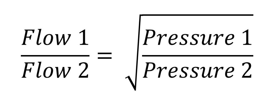
The exit tip has twice the flow-rate of the pre-orifice, and therefore operates at one quarter the pressure, or 15 psi. Recall the square-root relationship between flow rate and pressure.
The relationship between spray pressure and flow rate. Doubling the flow rate requires a quadrupling of pressure
That’s not the whole story. The internal venturi is drawing additional air into the nozzle chamber, and depending on the operating pressure, this could be from 5 to 15 psi. The amount added depends on the specific nozzle, its flow rate, and its pressure. Let’s add 10 psi in this case. The exit tip is actually at 25 psi.
Now let’s assume the pressure gauge reads 40 psi, and that the venturi generates 5 psi additional pressure. The actual exit orifice pressure is now only 15 psi. This is at the lower limit at which a spray is atomized, and at which a good pattern can form.
Our general recommendation with venturi-style low-drift tips has been to avoid pressures below 30 or 40 psi for that reason. We’re trying to prevent the spray becoming too coarse for adequate coverage, and also to prevent the spray pattern from collapsing.
The upside of this design is that the same principle allows for much higher-pressure operation without creating excessive drift. These types of nozzle can, in fact, be operated at 70 to 90 psi without becoming very drift-prone because the pressure at which the spray liquid is atomized is likely only 30 or 40 psi (the actual exit pressure and drift potential will depend on the nozzle and the formulation).
Speed Range
A low-drift nozzle with a pressure operating range from 30 to 90 psi (i.e., 3-fold) would have a flow rate range of 1.73 (i.e., the square root of 3 due to the square root relationship of flow rate and spray pressure). This means that the fastest travel speed (at 90 psi) would be 1.73 times the slowest travel speed (at 30 psi).
A conventional nozzle operating between 20 and 60 psi would have the same travel speed range. So why don’t we just do that? The main reason is that the two-stage design lowers the overall amount of drift substantially, something a conventional nozzle can’t achieve even at very low pressures.
A second reason is that even at high pressures, a two-stage design will likely drift less than an conventional nozzle. This is still the case if the conventional nozzle is operating at low pressures. Any spray quality chart comparing spray qualities of conventional and low-drift tips will demonstrate that.
Pulse Width Modulation
PWM uses a solenoid to intermittently shut off nozzle flow, between 10 and 100 times per second (Hz) depending on the manufacturer. This has implications for nozzle design because the nozzle must not leak liquid during the brief off-cycle. If it does, the small amount of liquid leaving the nozzle will not only not atomize properly, it will also cause a pressure drop within the nozzle which must be replenished with the next on-pulse. This will mean the on-pulse will operate at a lower initial pressure, affecting pattern development and atomization. For this reason, venturi-style low-drift nozzles have not been recommended with PWM. The venturi provides an alternate exit for air or liquid, compromising nozzle performance.
And yet, some venturi style nozzles do, in fact, produce acceptable patterns with PWM according to the nozzle manufacturers. This goes to show that nozzle design can continue to evolve to provide the best in drift reduction technology with PWM. Design for PWM suitability should be at the top of nozzle manufacturers’ agendas.
Nozzle design continues to evolve. But in the foreseeable future, spray pressure will continue to control pattern width and droplet size. That’s why understanding the pressure limits of any specific nozzle type, and maintaining pressure within those limits, is so important in any spray operation.
This article is reproduced, with permission, from Ohio State University Extension’s factsheet FABE-528.
Although nozzles are some of the least expensive components of a sprayer, they hold a high value in their ability to influence sprayer performance.
Nozzles meter the amount of liquid sprayed per unit area, controlling application rate, as well as variability of spray over the width of the sprayer boom. Nozzles also influence droplet size, affecting both target coverage and spray drift risk.
Nozzles come in a wide variety of types and sizes. The best nozzle for a given application will maximize efficacy, minimize spray drift, and allow compliance with label requirements such as application rate (gallons per acre) and spray droplet size. Selecting the best nozzle requires careful consideration of all the factors listed below:
Mode of action of chemical (spray coverage requirement)
Systemic
Contact
Application type (broadcast, band, directed, air assisted)
Target crop (field crops, vegetables, vineyard, shrubs and trees, etc.)
Spray drift risk
Nozzle Size
Each nozzle type is designed for a specific type of target and application. For example, a nozzle designed for broadcast spraying is not good for spraying pesticides over a narrow band. Luckily, most nozzle manufacturers’ catalogues have charts showing which nozzle type will be best for a specific job. Check the websites of nozzle manufacturers to reach their catalogues. For more information, contact your county Extension office.
Nozzle manufacturers’ catalogs provide tables and charts showing application rates (gallons per acre or gpa), given a nozzle’s flow rate (gallons per minute or gpm) delivered at various pressures (psi) and travel speeds (mph). These tables are useful tools for selecting the appropriate nozzles, pressure and speed to spray chemicals at application rates prescribed by product labels. However, the charts are only for a limited number of travel speed and nozzle spacing situations. There may be situations where the charts will not provide information associated with your sprayer setup (nozzle spacing) and operating conditions (travel speed and spray pressure). The Apps developed by most of the major nozzle manufacturers can provide you the exact nozzle flow rate required for any given set of application parameters, and identify a specific set of nozzle recommendations for the given application parameters.
To find these Apps, simply visit the App Store in your smart phone or tablet and do a search under “Spray Nozzle Calculator”, or some other key words related to nozzle size selection. You may also want to do a search under the name of the nozzle company from which you are interested in buying the nozzles. However, some Apps are not user friendly and sometimes they do not take into account the droplet size requirements when recommending nozzles. Although the Apps and tables in catalogues may expedite the nozzle size selection process, it is best to understand the procedure and the maths nozzle manufacturers use to generate the values listed in tables and to recommend nozzles in their Apps. The procedure used by the nozzle manufacturers to generate numbers in tables and in their Apps is explained below. By following the steps mentioned below, you should be able to determine the exact nozzle flow rate (gpm) required for your spray application parameters.
Once the exact nozzle flow rate is determined, you can then look at the catalogue to select the nozzle that will provide you the flow rate at a practical pressure setting.
Steps to select the proper nozzle size:
The following steps must be taken to determine the nozzle flow rate (gpm):
Select the application rate in gallons per acre (gpa). This is a management decision you will have to make based on pesticide label recommendations, field conditions and water supply.
Select a practical and safe ground speed in miles per hour (mph).
Determine the spray width per nozzle (W). For broadcast applications, W = nozzle spacing (distance between two nozzles on the boom) in inches. For band spraying, W = band width in inches. For directed spraying, W = row spacing in inches (or band width) divided by the number of nozzles per row (or band).
Determine the flow rate (gpm) required from each nozzle by using the following equation: gpm = (gpa x mph x W) / 5,940(5,940 is a constant to convert gpa, mph and inches to gpm).
Select a nozzle size from the manufacturer’s catalogue that will give the flow rate (gpm) determined in Step 4 when the nozzle is operated within the recommended pressure range. If a nozzle of this size is not available, change the travel speed in the equation above and determine the new flow rate required.
An Example
For example: You want to spray a pre-emergence herbicide at 15 gpa, at a speed of 8 mph. The distance between the nozzles on the boom is 20 inches. The herbicide label requires a spray quality of “Medium.” What should be the flow rate of the nozzle you will choose?
gpm = (gpa × mph × W) ÷ 5,940
Since this is a broadcast application (pre-emergence), W is the distance between nozzles (W = 20″). Filling in the variables yields the following calculation:
gpm = (15 gpa × 8 mph × 20 in) ÷ 5,940 = 0.4 gpm
This means, to apply 15 gpa at a speed of 8 mph with this sprayer setup, we need to select a nozzle with a flow rate of 0.4 gpm.
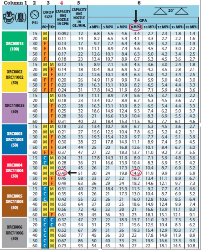
Now, we go to the nozzle catalogue, and find a nozzle that will give us a flow rate of 0.4 gpm, while operating the sprayer at an applicable pressure and travelling at 8 mph. Catalogues have charts for each nozzle, similar to the one shown on the next page. The first column gives the color code of the nozzle (which indicates flow rate), nozzle ID number, and the appropriate filter type for the nozzle. Column 2 gives the pressure range at which the nozzle should be operated. Column 3 gives the spray quality, a measure of spray droplet size (fine, medium, coarse, etc.) produced at different pressure settings. Columns 4 and 5 give the flow rate of nozzles in gallons per minute and ounces per minute, respectively, at different pressure settings. Column 6 gives gallons per acre application rate at different travel speed settings.
First, we need to find the best type of nozzle for our application. In their catalog, the nozzle manufacturer recommends a flat-fan pattern type nozzle for broadcast application of pre-emergence herbicides. Then we find a chart associated with the nozzle type recommended.
The chart shown happens to be for that type of a nozzle. Now we proceed with the process to determine the appropriate size of the nozzle.
Example of a typical nozzle rate table.
In our example above, the equation in Step 4 resulted with a flow rate of 0.4 gpm. Now, we look at Column 4 (gpm per nozzle) to determine the nozzle that provides us 0.4 gpm. Using the chart, we see that the nozzles XRC8004 or XRC11004 (shown in red) provide 0.4 gpm flow rate at 40 psi operating pressure. This nozzle also happens to provide Medium (designated with “M”) spray quality as recommended on the herbicide label. Under these operating conditions, this sprayer should apply 15 gpa at 8 mph as we expected. The validation of this is also evident on the chart. If you look at Column 6, choose 8 mph ground speed, the nozzle we selected will spray approximately 15 gallons per acre (14.9 gpa shown on the chart) at 8 mph travel speed and 40 psi spray pressure.
There may be multiple numbers of nozzles that can satisfy the 0.4 gpm flow rate requirements. However, they may not satisfy the desired spray quality and/or desired travel speed. It may be necessary to adjust pressure and/or travel speed according to nozzle selection. For example, the Brown XRC8005 nozzle is capable of producing 0.4 gpm, and achieving 15 gpa at 8 mph, if the spray pressure is reduced to about 25 psi. Similar calculations can be made using the equation below to come up with other GPM (flow rate) and PSI (pressure) combinations to satisfy the required 15 gpa application rate:
(GPM₁ ÷ GPM₂) = (√PSI₁ ÷ √PSI₂)
In this example, reducing the pressure to 25 psi alters the spray quality to “Coarse,” violating the label recommendation. When changing pressure is not an appropriate choice, the only other practical option is to change the travel speed. There is an inverse linear relationship between the travel speed (mph) and the application rate (gpa). The relationship is expressed by the equation:
Using the relationship above, we can determine that increasing the travel speed to 9.9 mph and keeping the sprayer operating at 40 psi will yield 15 gpa, as described below. The chart shown earlier indicates when using XRC11005, GPA₁ = 18.6 at 8 mph (MPH₁) at 40 psi. We want to find out what the new travel speed (MPH₂) should be to achieve 15 gpa (GPA₂). Using the equation above:
However, increasing travel speed to 9.9 mph may not be practical or safe. When changes to pressure or travel speed as dictated by the equations above are neither practical nor safe, it may be necessary to select a different nozzle.
In this example, it looks like the best nozzles to use for our application situation are XRC8004 or XRC11004, both providing 0.4 gpm at 40 psi. The only difference between these two nozzles is in the angle of spray pattern: one produces an 80 degree fan pattern (XRC8004), while the other one (XRC11004) produces a 110 degree fan pattern. Due to the difference in the angle of the spray pattern, each of these nozzles require different boom heights to obtain proper overlap between two adjacent nozzles.
Calibrate the sprayer
Selecting the right type and size of a nozzle is not sufficient to end up with accurate, effective and efficient application of chemicals sprayed. Changes in ground conditions (tilled, un-tilled, grass, wet, dry), and the topography of the field sprayed (flat, sloped) will affect the ground speed which is one of the variables used in determining the correct nozzle size. Nozzle orifices wear out with time causing larger flow rates and distorted spray patterns than when they were new. The gpm flow rate values given in catalogues or in Apps are based on spraying water only. Spraying solutions with higher densities than water (most spray solutions are) will affect the flow rates of nozzles at the same spray pressure. For the reasons mentioned above, sprayers should be calibrated frequently, especially when the field conditions change, to determine the actual application rate.
Calibration is easy, and there are many ways to do it. regardless of the method chose, three measurements will be taken:
actual ground speed,
the distance between nozzles, and
nozzle flow rate for a given length of time.
One easy method is explained in an OSU Extension Publication (AEX 520) listed in the references at the end of this article.
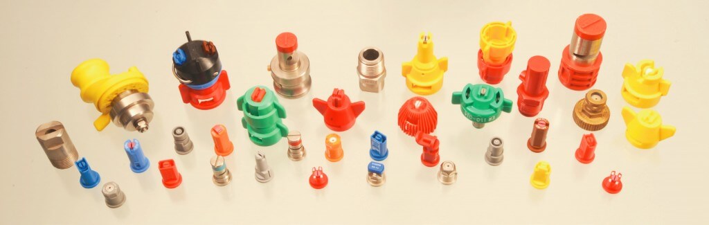
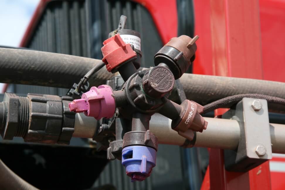
Keep several types of nozzles on the boom
Remember that one specific type of nozzle will not be best for all applications. For this reason, it is best to have several types and sizes of nozzles on the boom so that you can switch to the “best” nozzle choice for a given spraying job. As shown in the pictures below, there are various types of sprayer components and setups you can buy to configure your boom so the new set up allows you to easily switch from one nozzle to another instantly.
Keep spray drift in mind when selecting nozzles
One of the major problems challenging pesticide applicators is spray drift, which is defined as movement of pesticides by wind from the application site to an off target site. Drift is influenced by many factors which are discussed in detail in two OSU Extension publications (Bulletin 816 and AEX-525) listed in the references at the end of this article. Equipment, especially the nozzles, used to spray pesticides play a significant role in generating as well as reducing spray drift. In nozzle catalogues, you can see a number of different nozzles of the same type, in terms of spray pattern. For example, one can find nozzles within the same “flat-fan” category classified as “low-drift.” Research conducted at Ohio State and elsewhere clearly indicate that nozzles labelled as “low-drift” significantly reduce spray drift as discussed in OSU Extension publication AEX-523 (listed in the references below). If drift is, or becomes a concern, it may be best to switch from a conventional flat-fan nozzle to a “low-drift” flat-fan nozzle with the same flow rate. Therefore, it is best to have more than one type of a “flat-fan” pattern nozzle on the boom.
Summary and conclusions
Nozzles are typically the least costly items on a sprayer, but they play a key role in the final outcome from a spraying job: achieving maximum efficacy from the pesticide applied while reducing the off-target (drift) movement of pesticides to minimum. Pesticides work well if the rates on labels are achieved during application. This can be achieved only if the right nozzle type and the proper size of the nozzles are on the sprayer, and the sprayer is operated properly.
Although the Apps and tables in catalogs may expedite the nozzle size selection process, it is best to understand the process and the math nozzle manufacturers use to generate the values listed in tables, and to generate nozzle recommendations in their Apps. This procedure, explained in this publication, hopefully will help you to determine the exact nozzle flow rate (gpm) required for your spray application parameters, while highlighting some other important parameters such as spray pressure, droplet size, spray coverage on the target, and drift, all of which should be given serious consideration when selecting the best nozzle for a spraying job.
Acknowledgments
The author thanks Mary Griffith, Agriculture and Natural Resources Extension Educator, OSU Extension; Dr. Larry C. Brown, Professor and Extension Specialist, Department of Food, Agricultural and Biological Engineering, The Ohio State University; and Dr. Robert “Bobby” Grisso, Professor and Associate Director, Virginia Cooperative Extension, Virginia Tech University, Department of Biological Systems Engineering; for reviewing this publication and for their editorial contributions.
References
Ozkan, E. Calibrating boom sprayers. Ohio State University Extension publication AEX-520, Columbus, Ohio.
Ozkan, E. New nozzles for spray drift reduction. Ohio State University Extension publication AEX-523, Columbus, Ohio.
Ozkan, E. and R.C. Derksen. Effectiveness of Turbodrop® and Turbo Teejet® nozzles in drift reduction. Ohio State University Extension publication AEX-524, Columbus, Ohio.
Ozkan, E. and H. Zhu. Effect of Major Variables on Drift Distances of Spray Droplets. Ohio State University Extension publication AEX-525, Columbus, Ohio.