Small-plot agricultural sprayers should have a pressure gauge on the wand or boom to ensure accurate application rates. Most are added after-market and the operator has the choice of buying liquid-filled or dry gauges.
Glycerine- or silicone-filled gauges are preferred because
they dampen pressure spikes, pulsation and mechanical vibration. Compared to
dry gauges, they are available in higher ranges and are less prone to moisture
problems (which cause corrosion, accuracy and visibility issues).
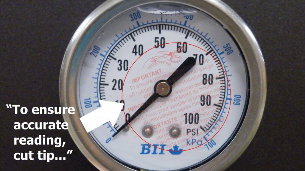
We use 100 psi (~7 bar) liquid-filled gauges for our handheld
sprayers. Only recently did we acknowledge the sticker affixed to the glass advising
the user to cut the nipple off the rubber plug located at the top. Preferring
to avoid messy leaks, we have always left it intact.
We wondered what impact, if any, this was having…
What are Vents?
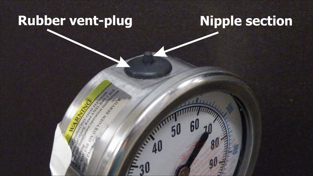
Expensive gauges have mechanical vents that can be opened prior to use and closed to retain liquid when stored. More commonly, there is a rubber plug with a protrusion (referred to as a nipple).
Why Vent?
Mechanical, liquid-filled gauges are sealed to keep the
liquid in. When there are temperature fluctuations, the liquid expands or
contracts and creates “case pressure”. This exerts a force that interferes with
the pressure reading.
According to Marshall Instruments, case pressure can offset the accuracy by approximately 1 psi (0.07 bar) for every 35˚F (20˚C) temperature change, but is only noticeable when measuring lower pressures (0-15 psi or 0-1 bar). Nevertheless, they advise all gauges should be vented prior to use.
The plug can be removed to allow the user to refill the gauge, maintaining an air space of about ½” at the top of the window. If the nipple is cut off, the gauge is permanently vented and will leak if the gauge is not kept vertical.
Testing
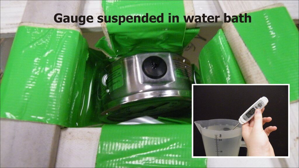
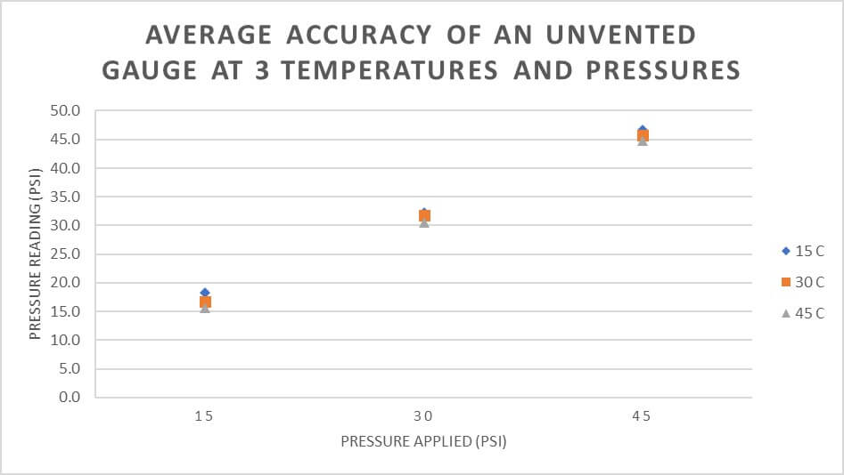
We performed an experiment to see if typical working temperatures had a practical impact on the accuracy of an unvented gauge. We suspended an unvented, liquid-filled gauge upright in a water bath at approximately 15˚C, 30˚C or 45˚C (59˚F, 83˚F or 113˚F) until it equilibrated. The high temperature may seem unreasonable, but gauges left in trucks on summer days get far hotter.
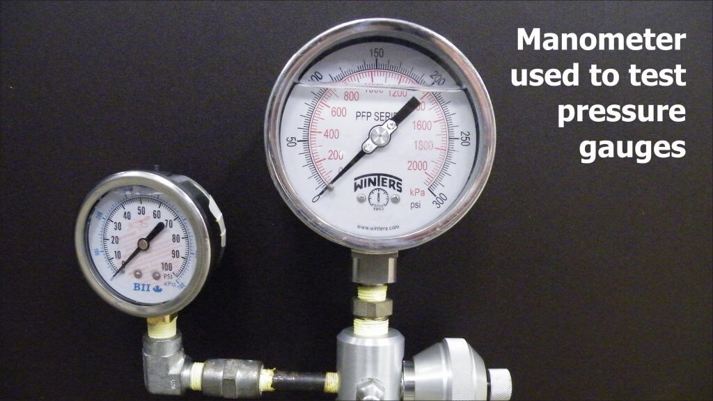
The gauge was quickly removed and placed in a manometer
(Ametek T-975) where it was subjected to pressures of 15, 30 and 45 psi (1 bar,
2 bar and 3.1 bar) and readings recorded. This was repeated five times. We then
vented the gauge and repeated the process.
Results
At first, there appeared to be very little difference in average accuracy of vented and unvented gauges. Accuracy refers to the closeness of a measured value to a standard or known value. Perhaps there was some small increase in the pressure reported by an unvented gauge, but very little practical difference.
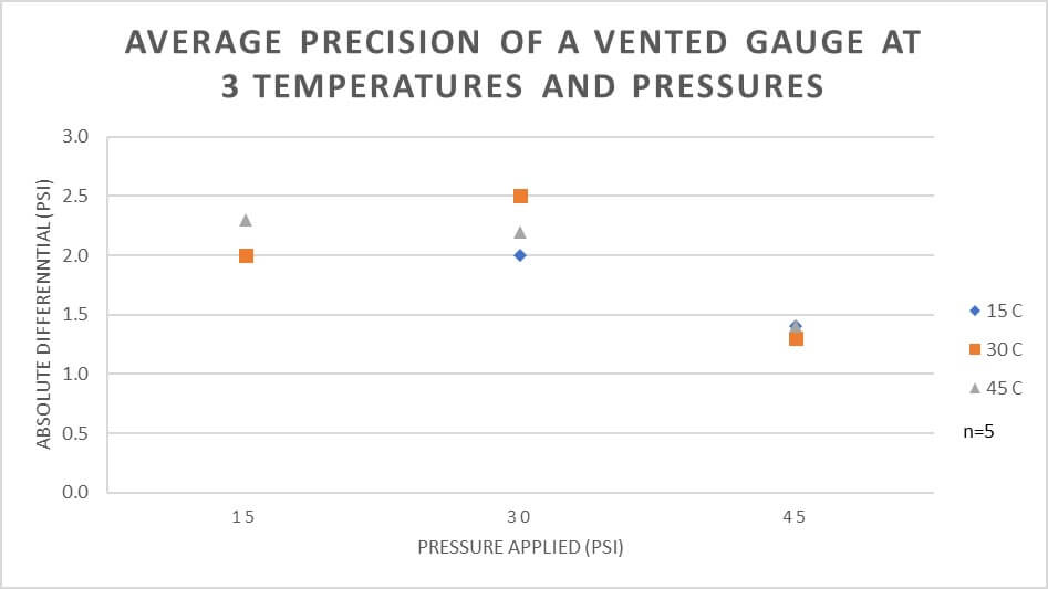
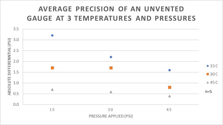
However, when we look at variability we get a different picture. Variability is a measure of precision, which refers to the closeness of measurements to one another. The graphs show that an unvented gauge has greater variability (less precision) at lower temperatures and lower pressures.
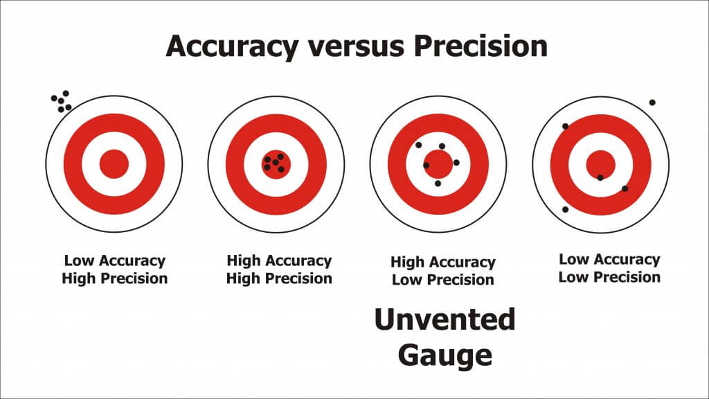
A good way to think of accuracy and precision is using the classic archery bulls-eye metaphor. The unvented pressure gauge is best represented by the third image, where it is accurate (on average) but not precise (variable).
Real-World Example
What does this mean in practice? Consider someone spraying a small plot using a TeeJet XR8002 nozzle on a CO2-powered hand boom at 30 psi. The difference in output between 30 psi and 40 psi is about 0.003 gpm / psi.
An unvented pressure gauge used on a hot day may read 1.5 psi lower, causing you to overcompensate and raise the pressure 1.5 psi higher than intended. That would result in 0.0045 gpm (0.5%) more applied. Compensating for an unvented gauge on a colder day might be closer to 0.009 gpm (1%) more applied.
Assuming a walking speed of 3.1 mph (5 km/h) and a swath of 20” (50 cm), the nozzle should emit about16.3 gpa at 30 psi. Unvented in the heat, that’s 16.7 gpa. At 33 psi, that’s 17.15 gpa. That’s almost 1 gpa more than intended. Potentially, the lack of precision could make a significant difference.
Conclusion
Liquid-filled gauges are preferred over dry gauges.
To ensure precision, the gauge should be vented prior to use.
Permanent venting on a hand-held sprayer causes leaks, which is a nuisance, so we suggest simply lifting the edge of the plug with a screwdriver or fingernail to vent the gauge prior to each use.
This work was performed by OMAFRA summer student, Aidan Morgan.
Enjoy our take on a Dr. Seuss work-of-art. We’re sure the fine doctor would want to end resistant pig weed’s reign of terror as much as we do. Hear us recite it in the sound bar, read it yourself, or head to the bottom of the article to see the talented Bridgette Readel (@bmreadel) read it for you. Enjoy!
Press Play to hear the audio version of this article
In the home farm’s west field, where the soybeans won’t grow, and the wind blows the soil from deep tillage you know, and no pollinators come, excepting old crows is the patch of resistant pigweed.
And downhill in the boundary, some neighbours say, if you look close enough you can still see today, where herbicide persisted, in the places it drifted, from the winds that took it away.
How did it drift? How did it get there? And why was it lifted and taken somewhere from the home farm’s west field where the soybeans won’t grow? Look to the sprayer. Look close, and you’ll know.
You won’t see Coarse nozzles. You will see high booms that wobble and bounce on a sprayer that zooms in headwinds too high in the late afternoon. They may even spray by the light of the moon!
Check the chemical shed. Crack the door, just a fraction. You’re likely to see A lone mode of action.
“Tell me how,” says the farmer “I’ll do what you say.” “But I only have so many hours in the day to spray the west field where the soybeans won’t grow, and battle the pigweed that simply won’t go.”
“Oh the things you can do! So much can be done!” “Learn to spray in light winds, in the day, in the sun!” “Lower booms, use more water, use droplets so Coarse.” “We’ve told you before… (you will note we are hoarse.)”
The farmer said nothing, just gave us a glance. We could tell he was thinking of time, effort and cash. “Driving slow improves coverage, and you can make up the time, with faster fills, longer booms, and more precise A-B lines.”
That was long, long ago. Let’s check in today, and see if the problems have withered away.
In the home farm’s west field, where the soybeans now grow, and cover crops cling to the soil down below, the pollinators buzz because drift doesn’t blow.
Variable rate spray application is receiving a lot or attention with our increased ability to farm according to prescription maps. For dry products such as seed or fertilizer, metering is relatively straight-forward and variable rate application has been possible for many years. However, liquid product application has been more complex and requires special approaches
Hydraulic Pressure and Flow Rate
In conventional liquid metering, the liquid is forced through a metering orifice that is placed in-line. This could be an orifice plate for liquid fertilizer, or a flat fan nozzle for pesticides. Rate control is achieved by altering the spray pressure. It is usually impractical to change the nozzle or metering orifice during an application.
The main drawback to this approach is that spray pressure is not very effective at changing flow rates due to the square root relationship between spray pressure and flow rate.
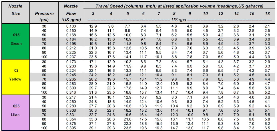
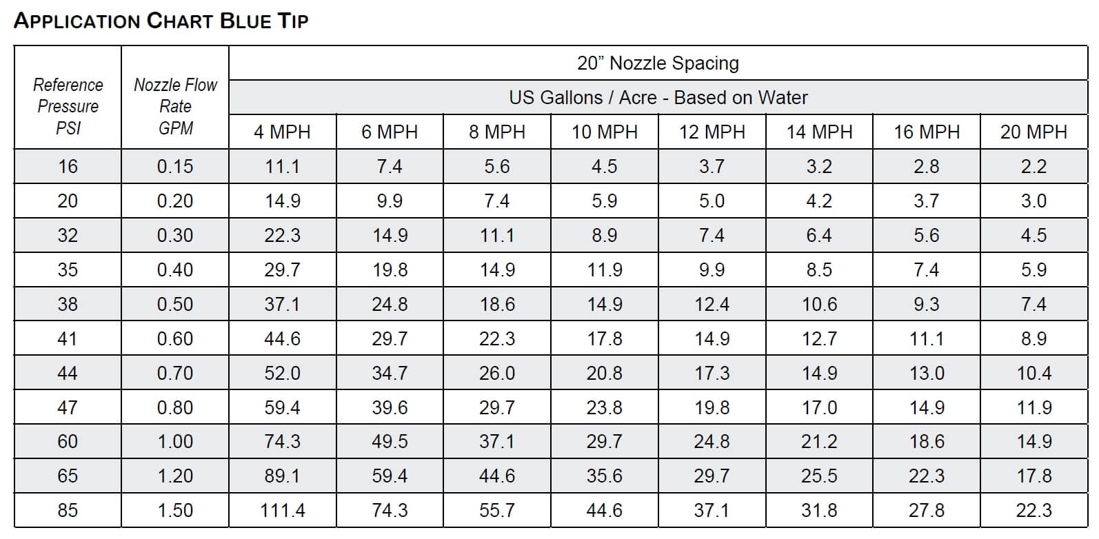
For example, with reference to the table below, one can see that doubling the spray pressure (say, from 30 to 60 psi) only increases the flow rate by 40%. Tripling the pressure (from 30 to 90 psi) increases the application volume by 73% (we can call that a factor of 1.73). As a result, the use of pressure alone doesn’t offer a large range of application rates, and we accept a factor of 2 to be the limit for fertilizer streamer and broadcast nozzles (meaning a four-fold pressure range) and a factor of 1.73 to be practical for broadcast pesticide sprays over a 3-fold pressure range. Any wider application volume range would require adjustment to travel speed.
With these inherent limitations in flow rate capacities from hydraulic pressure alone, applicators are often forced to use wide pressure fluctuations to achieve reasonable rate responses. In some cases, this means that pressure needs can be too low for uniform distribution, or too high for pump or plumbing capacities.
For Variable Rate application, we are less interested in travel speed range, and are more interested in flow rate range. The above chart can be used for both purposes. In the above example, rows under each application volume identify the travel speed range. These headings can be flipped, so the 10 gpa column (with mph values in it) can also be a 10 mph column (with gpa in it). the numbers don’t change. same is true for metric units, except the convenience of being in the same magnitude that makes the flip easy in US units is absent.
There are a few options available that expand the flow rate range of liquid products. A brief overview of the main options follows:
Greenleaf / Agrotop
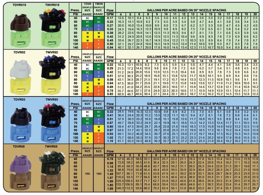
TurboDrop Variable Rate (TDVR): This nozzle appears like the traditional TurboDrop family, but has an innovative dual orifice in its venturi. The first stage is always open, but the second orifice is held closed under spring pressure until a certain threshold is reached. This design achieves a 3-fold flow rate range between 40 and 140 psi. Below the 40 psi threshold, the spray pattern fan angle deteriorates quickly.
TurboDrop VR tip provides about 3-fold flow rate range at any given speed, but requires higher pressures.
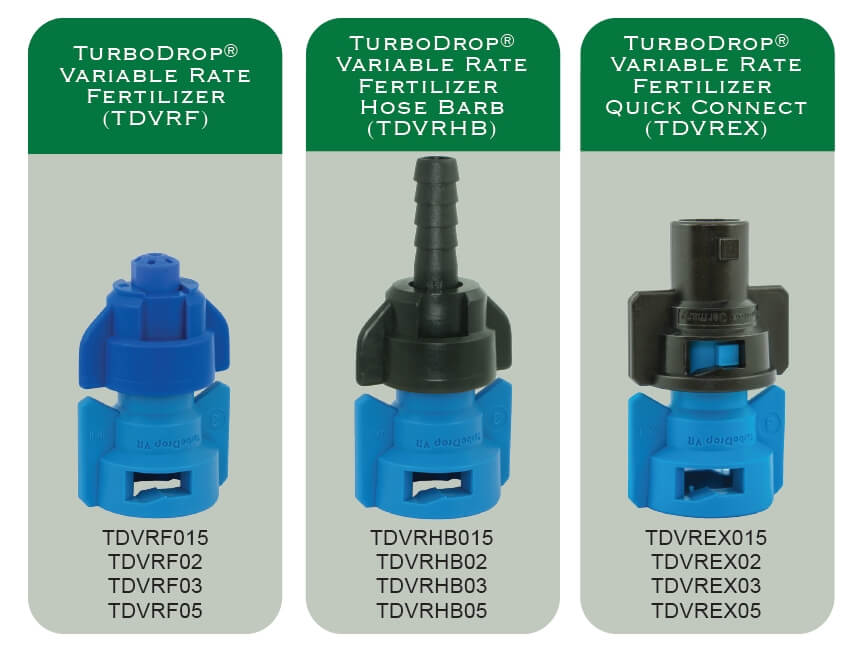
TurboDrop Variable Rate Fertilizer (TDVFR): Because fertilizer streams do not need to atomize the spray or form a fan, the minimum pressure can be reduced, in this case to 10 psi. From 10 to 140 psi, this design offers a four- to five-fold range of flow rates. Three exits are offered, a streamer, a hose barb, and a quick connect.
Three variants of the variable rate fertilizer orifice are offered by Greenleaf.
VariTarget Nozzle
This nozzle design uses a spring-loaded plunger to exert force on a flexible nozzle cap, deflecting it slightly. The deflection changes the orifice size, allowing for a change in flow. As a result, the flow rate response to a pressure change is increased dramatically. A single VariTarget nozzle equipped with a blue or green nozzle cap can deliver flows ranging from 0.2 US gpm at 20 psi to 1.2 gpm at 65 psi, for a stunning 6-fold change in application rate (link).
The VariTarget nozzle body
The main drawback of this nozzle is the poor metering accuracy of the system. In calibration tests, flows from various new VariTarget nozzles operated at the same pressures varied by more than 10%. While this amount of variability may be acceptable in liquid fertilizer application, it is not considered acceptable for pesticide application. Tightening or loosening the threaded spring cap even a little changes the flow.
TeeJet Variable Rate Fertilizer Assemblies
These metering assemblies, introduced in 2016, offer an elastomer (EPDM) metering plate whose orifice diameter expands with pressure, offering a wider range of flows. There are no moving parts in the assembly. Four models are available (link).
PTC-VR: Using a push-to-connect design for planters and toolbars, it offers versions that accomodate 1/4″, 5/16”, and 3/8” OD tubing diameters
QJ-VR Hose Barb: This unit offers hose barb diameters for 1/4″ and 3/8” ID hose.
Both units feature a pressure range of 10 psi to 100 psi, within which a flow rate range of approximately 8-fold is possible.
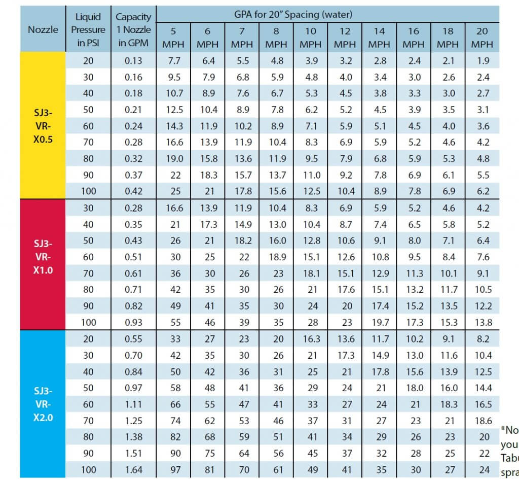
SJ3-VR: This unit generates three streams and operates over a pressure range of 20 to 100 psi, offering a flow rate range of about 3-fold.
GPA ranges for specific travel speeds for TeeJet SJ3 VR
SJ7-VR: Generating seven streams and operating over a pressure range of 30 to 80 psi, this unit allows a flow rate range of about 2.9.
In all cases, the realized flow rate range is significantly greater than would have been achieved with pressure change alone. TeeJet has tested the flow rate variance among units operating at the same pressure and has found them to be acceptable, according to company representatives.
Fertilizer banding has greater tolerances for application because pattern width is less important, and also because stream stability is less affected by pressure than spray pattern droplet size.
Pulse Width Modulation (PWM)
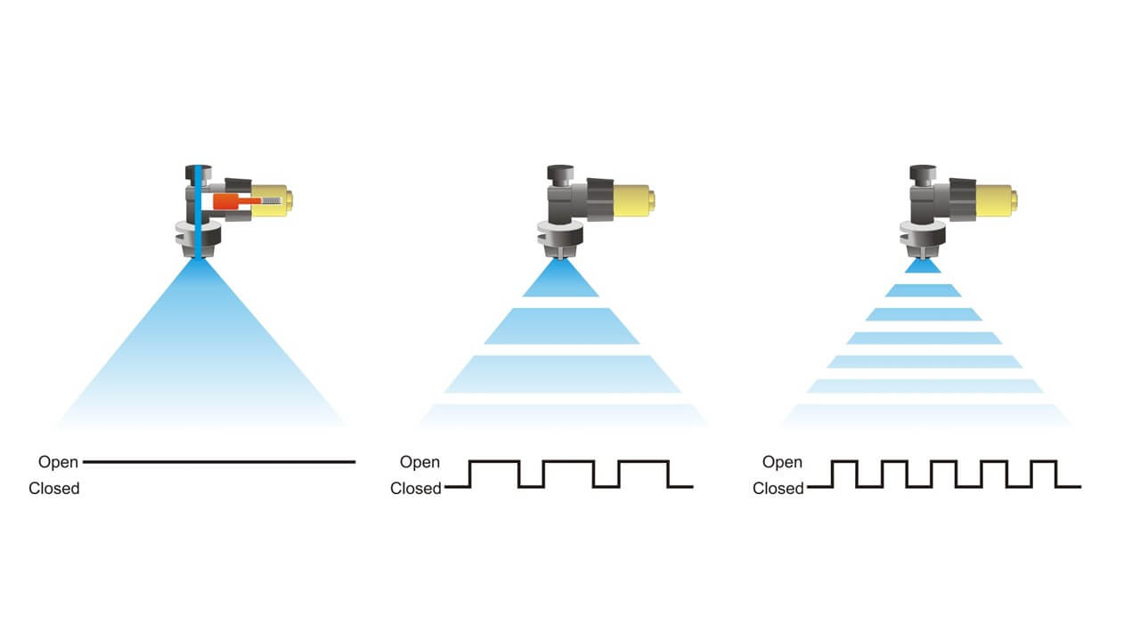
PWM utilizes conventional plumbing: a single boom line and a single nozzle at each location. Liquid flow rate through each nozzle is managed via an intermittent, brief shutoff of the nozzle flow activated by an electric solenoid that replaces the spring-loaded check valve. Typical systems pulse at 10 or 15 Hz (the solenoid shuts off the nozzle 10 or 15 times per second), and the duration of the nozzle in the “on” position is called the duty cycle (DC) or pulse width.
100% DC means the nozzle is fully on, and 20% DC means the solenoid is open only 20% of the time, resulting in the nozzle flowing at approximately 20% of its capacity. This is illustrated in the figure below. The ability to control the duty cycle is referred to as pulse width modulation.
The system has a theoretical flow rate range of about four- to five-fold. Within this range, spray pressure, and the corresponding spray pattern and droplet size, stay roughly constant. This makes it ideal for variable rate pesticide application, where spray patterns and spray quality are critical for performance.
The main disadvantage of this system, compared to the variable orifice designs, is cost. Although highly accurate and dependable, commercial sprayer units are priced between $15,000 and $65,000 per sprayer, depending on features and boom widths. The available systems are Capstan PinPoint II and EVO (as a retrofit to any sprayer), Raven Hawkeye (retrofit to any sprayer, available as factory option on Case (AIM Command), New Holland (IntelliSpray) and most other brands, John Deere ExactApply, WEEDit Quadro, Agrifac StrictSprayPlus and TeeJet DynaJet (available as retrofit). See our in-depth article on PWM for more information on these systems.
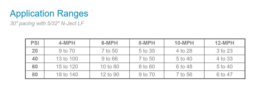
For ammonia and liquid fertilizer planters or toolbars, Capstan offers three different PWM products, N-Ject NH3, N-Ject LF or EVO LF. These systems offer more control over PWM pulse frequency and duty cycle and can achieve 8-fold rate ranges.
Flow rate ranges for Capstan N-Ject LF, on 30″ spacing
At low frequencies and duty cycles, the mobiliy of the fertilizer in soil needs to be considered, as significant gaps in a stream can be generated.
A variable rate for liquid fertilizer system for seeders, together with sectional control and turn compensation, is offered by Capstan EVO-LF. This system can generate 10 to 60 gpa at 4.5 mph on 12″ spacing.
Dual Boom Systems
A second boom fitted with different flow nozzles is installed, and is activated when the flow rate requirements can no longer be met with a single set of nozzles. Once the second boom is activated, the spray pressure drops significantly and additional flow capacity can be realized.
Dual boom system
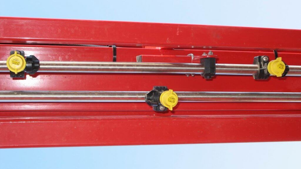
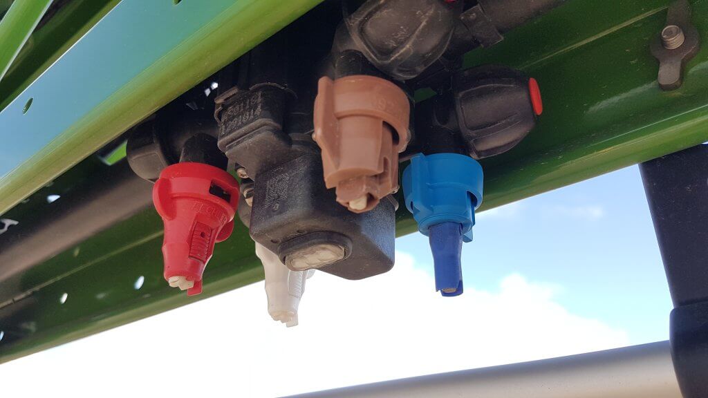
Dual or Quadruple Nozzle Bodies
A similar approach to the dual boom is available as selectable nozzles in the same body from Arag (Seletron), Hypro (Duo React), John Deere (ExactApply) Amazone (AmaSelect), and others. These systems utilize a single boom and direct the flow through one of any two (Duo React, ExactApply, Seletron) or four (Seletron, others) nozzles, or several nozzles at the same time.
AmaSelect utilizes a unique switching system that allows the user to select only Nozzle 4, Nozzle 3, Nozzles 3 & 4, and Nozzles 2 & 4, making the placement of certain sized nozzles critical.
Amazone AmaSelect nozzle switching system
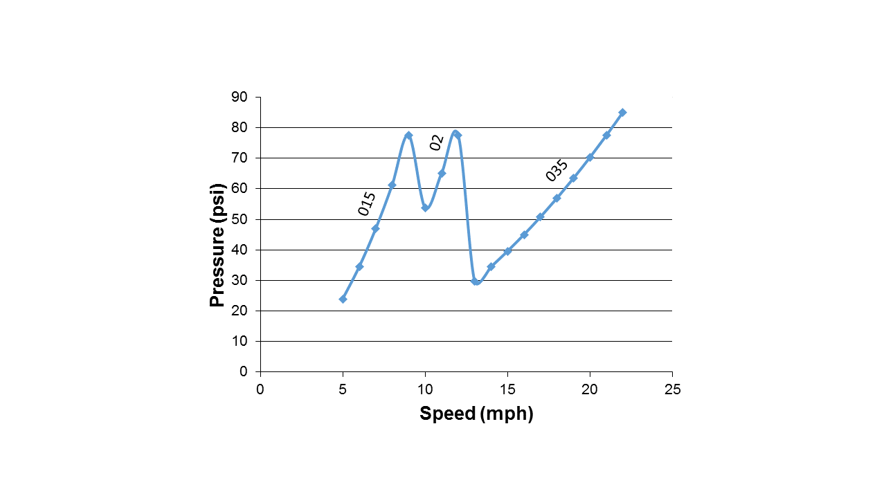
Similar pressure fluctuations as with a dual boom would be experienced, requiring careful selection of nozzle flow rates to avoid large pressure jumps. The system can also be used to manually change from one nozzle to another as needed. In the figure below, the pressure changes associated with the sequential use of 015, 02, and 035 flows are shown.
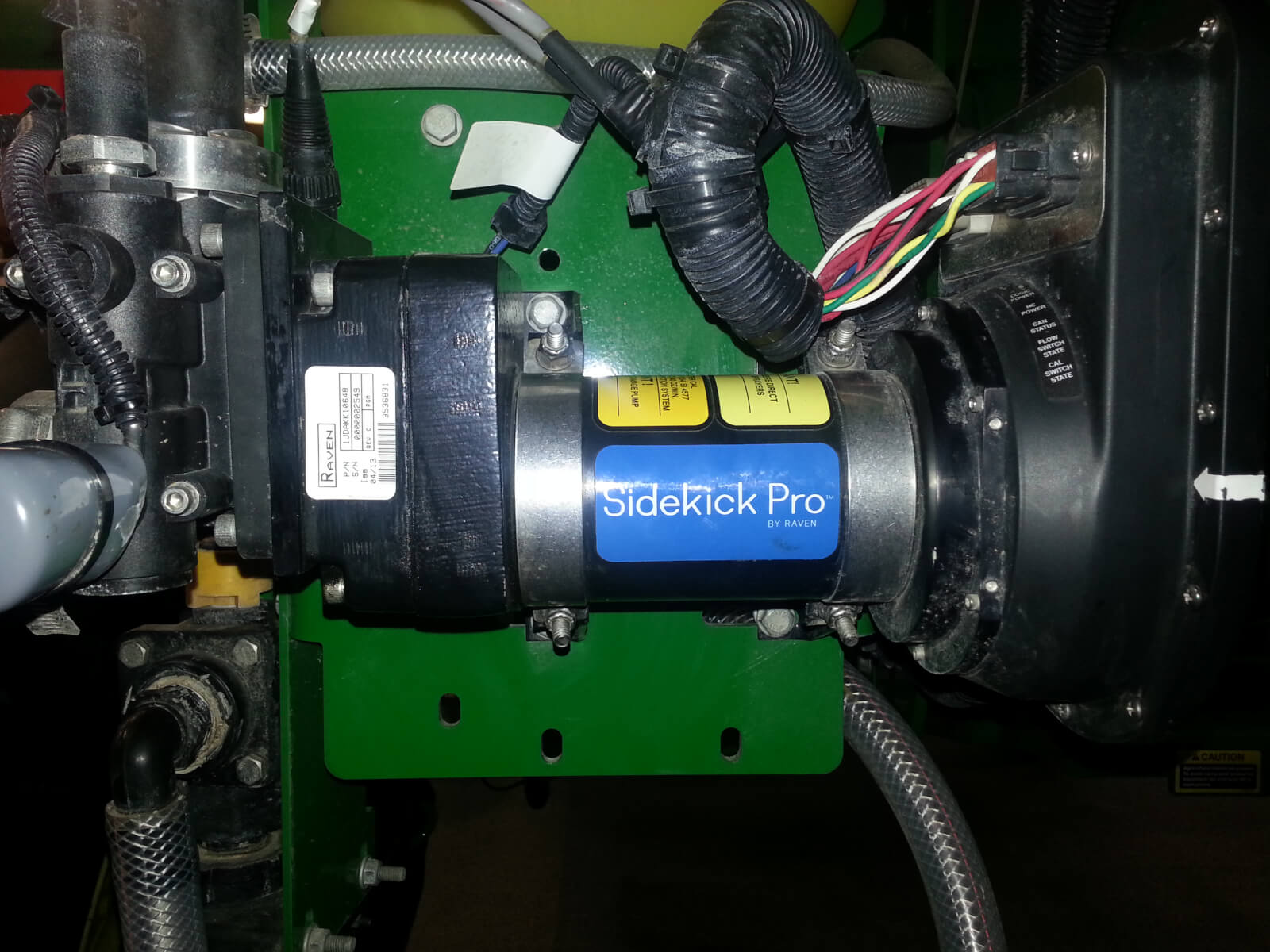
Direct Injection
Direct injection is an option for variable application of pesticides. In this system, undiluted pesticide is placed into canisters on the sprayer, and plain water (or water plus adjuvant) is in the sprayer tank. The chemical is metered and introduced into the water on the pressure side at some distance upstream from the boom sections. The pesticide rate can be varied with the speed of the direct injection pump, offering a very high dynamic range of possible rates. For example, Raven’s Sidekick Pro (available as factory option on Case and John Deere sprayers, or as a retrofit to any sprayer) offers a 40-fold range of flow rates.
After injection, an in-line mixer ensures that products are evenly distributed in the carrier. The amount of lag in the systems will depend on the amount of spray mixture in the plumbing upstream of the nozzles, the total boom flow rate, as well as the boom section configuration. With a variable rate map this lag can can be anticipated and accommodated.
Pump technology has improved the metering accuracy over a range of viscosities. However, dry formulations remain a challenge as slurries can settle and create problems for the pump and screen components.
Summary
High dynamic flow rate ranges for agricultural sprays are challenging to achieve, but will become more important as interest in site-specific management increases. Relatively inexpensive solutions are available for liquid fertilizer, whereas pesticide sprays require greater investments in technology to preserve spray pattern integrity. As mapping sophistication continues to grow, these application technologies will be integral to variable input prescriptions.
Some years ago, a friend recommended that I read The Tipping Point by Malcolm Gladwell. In this book, Gladwell tries to understand why some things catch on, and others don’t. It’s a compelling read full of Gladwell’s trademark stories and his knack to deftly interpret scientific studies. He talks of connectors, mavens, and salesmen, as well as the “stickiness factor”, a measure of how memorable something is, as keys to success of products and ideas. I think of the book often as I ponder the many good ideas in agriculture, many of which never see widespread adoption.
One of these good ideas is spot spraying. Green-on-brown detection was first introduced in the early 1990s. Anyone remember the Concord DetectSpray? It was great but had bad timing, as resistance wasn’t a big issue and glyphosate prices were about to slide. Green-on-brown grew to the NTech (later Trimble) WeedSeeker a few years later. Rometron’s WEEDit built on Trimble’s success and found widespread adoption in Australia in the past ten years. Spot spraying did not gain any traction in North America during this time.
Australia is unique in many ways, not the least of which is their summer spraying practice. Summer is the hot, dry season where land is typically fallow and weeds are kept in check with herbicide sprays (aaaah, the serenity). Making several passes over a field, combined with the need to control some larger and hardy plants, is expensive, and a spot spray saves much of the cost. The savings can be put to use with more effective herbicide tank mixes that delay the onset of herbicide resistance. Spot sprays pay for themselves in short order Down Under.
It’s more of a challenge in the northern plains of North America, where the fallow season involves snow cover and burnoff occurs in a short window before seeding and sometimes after harvest. But nonetheless, spot sprays have a fit for many of the same reasons.
WEEDit is the first system to make serious inroads in North America, with several dozen systems having been retrofitted to high-clearance sprayers. High detection accuracy and hardware reliability is proven in three seasons.
On March 2, 2021, John Deere entered the Green-on-brown spot spray area with See & Spray Select. This not to be mistaken as competition. Instead, the entry of a major brand provides validation of the concept like only a large manufacturer can. Yes, we’ve reached a tipping point.
While the first Green-on-brown units are becoming established, Green-on-green, the ability to detect weeds within a crop, continues to be developed around the world. French startup Bilberry has made enough gains in Australia to bring its product to market with Agrifac, where it’s called AIC Plus. In farmer field trials, they have achieved 90 per cent detection accuracy of wild radish in Western Australia, and claim that they are ready for broadleaf weed identification in wheat, barley and oats. Bilberry’s technology will also be seen on Australia’s Goldacres and France’s Berthoud. Other startups, notably Israel’s Greeneye Technology, plan to introduce a Green-on-green system in the U.S. in the near future. Amazone, the German farm equipment giant, partnering with Xarvio and Bosch, announced plans at Agritechnica to have a commercial unit for sale by 2021.
This technology will have significant impact on sprayer design philosophy. At present, productivity is synonymous with capacity, and large tanks with commensurate heavy and powerful tractor units dominate. Spot spraying savings will depend on weed density and hardware resolution, but 50 per cent to 90 per cent reductions in spray volume can be expected. A 1,600-gallon tank would no longer be necessary. The savings in frame weight and horsepower would be significant, as would the time savings from less intense tendering demands. These savings would offset the lower driving speeds that accompany sensing technologies, and, overall, provide a lower bar for autonomous operation. We may see lighter specialty spot sprayers.
The savings in brute size will be countered by increased sophistication. Better boom height management is essential for spot spraying, not just for the sensor to properly see the target and estimate the time needed for the boom to reach that spot, but also for the spot spray itself to deliver the right dose. In any fan spray, band width at ground level changes with height, and that, of course, is related to dose. Trailed booms can address this issue easily.
But not everyone wants a specialty spot sprayer that would require an extra pass over the field. With growing utility of soil residual herbicides, dual tank sprayers—small tank for the spot spray, large tank for the broadcast residual—make sense. Large sprayer frames can accommodate an additional smaller tank, second pump, and plumbed boom easily.
Plant detection and identification bring other opportunities. Adjusting dose for plant size is one of the first, or for harder to control weed species.
Spot sprays rely on fast, precise response of the nozzle, and this provided by fast-reacting solenoids that are part of pulse-width modulation (PWM) systems. On a broadcast sprayer, these solenoids can change the emitted dose instantly, within a certain envelope, by altering the duty cycle of the pulse. This, however, works best in the context of a boom with overlapping spray patterns. A single band spray would not change dose with duty cycle as easily.
Higher dosing would be an opportunity for multiple nozzle bodies that are able to spray one, two or more nozzles in the same spot simultaneously. These are already widely available and popular in Europe.
This also brings direct injection into play. Current systems introduce the active ingredient into the boom upstream of the nozzles, affording it time to mix into the water. For true spot spray utility, though, direct injection ought to be at the nozzle. Only then can custom mixes and rates be applied on a spot basis. It’s been done before, if only to show how difficult it would be to deliver uniform doses to a spot spray machine.
Spot spray sensors have agronomic benefits. By recording the location sprayed, weed patches can be mapped. As plant identification becomes possible, it’s conceivable to obtain plant species and stage distribution maps from the spray pass That would turn the sprayer into a high-resolution crop scouting tool. As machine learning and sensor sophistication grows, other plant and soil parameters can be mapped. The agronomic value of such maps, especially if created over the course of the growing season, is immense. Of course, data density, handling, storage, and analysis will constrain this.
If the past has taught us anything, it’s that there seems to be a appetite for investment in farm equipment. Sprayers have been the most-used implement on the farm for some time, and their popularity continues despite sharp price increases. These new capabilities will only add value to these implements. Prepare for sticker shock, followed by acceptance and adoption.
What will a future spot sprayer look like? Although it will have tanks and booms, the level of electronic sophistication will make it so much more versatile we can’t yet imagine all the ways in which it might be used. But it seems to me the situation has tipped and we’re already accelerating toward that future.
On March 2, 2021, John Deere entered the optical spot spray (OSS) market with its first product, See & Spray Select™. This “Green on Brown” system identifies green material on a non-green background and is thus suited for pre-seed burnoff, chem fallow, or post harvest. It is competing for the same market space as Cropland’s WEEDit and Trimble’s WeedSeeker, but uses a slightly different approach.
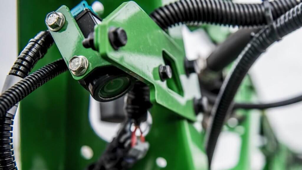
At the heart of the See & Spray system is a relatively simple RGB camera that is mounted directly to the boom and looks about 1.5 m ahead. When this camera detects a spot of green colour, it assumes that this is a plant and activates a nozzle in line with that plant. John Deere says the weed size threshold is about ¼” (6 mm), and is evaluating its experimental data to identify exceptions to that rule of thumb.
See & Spray Select uses an RGB camera to detect weeds (Image courtesy John Deere)
In 2017, John Deere conducted a highly publicized acquisition of Blue River Technologies, a start up that pioneered artificial intelligence (AI) plant identification and coined the term “See & Spray”. However, the technology John Deere announced this time originated with the University of Southern Queensland near Toowoomba, Australia. The university’s Centre for Agricultural Engineering had received some initial seed financing from Sugar Research Australia, Cotton Research and Development Corporation, and Hort Innovation, and eventually partnered with John Deere. This is yet another example of the value of farmer investments in research.
Blue River contributed to this project but remains committed to its path of developing Green on Green OSS through machine learning. John Deere says this first product is part of an evolution of spraying with ever-increasing precision that will culminate in spot spraying weeds within a canopy.
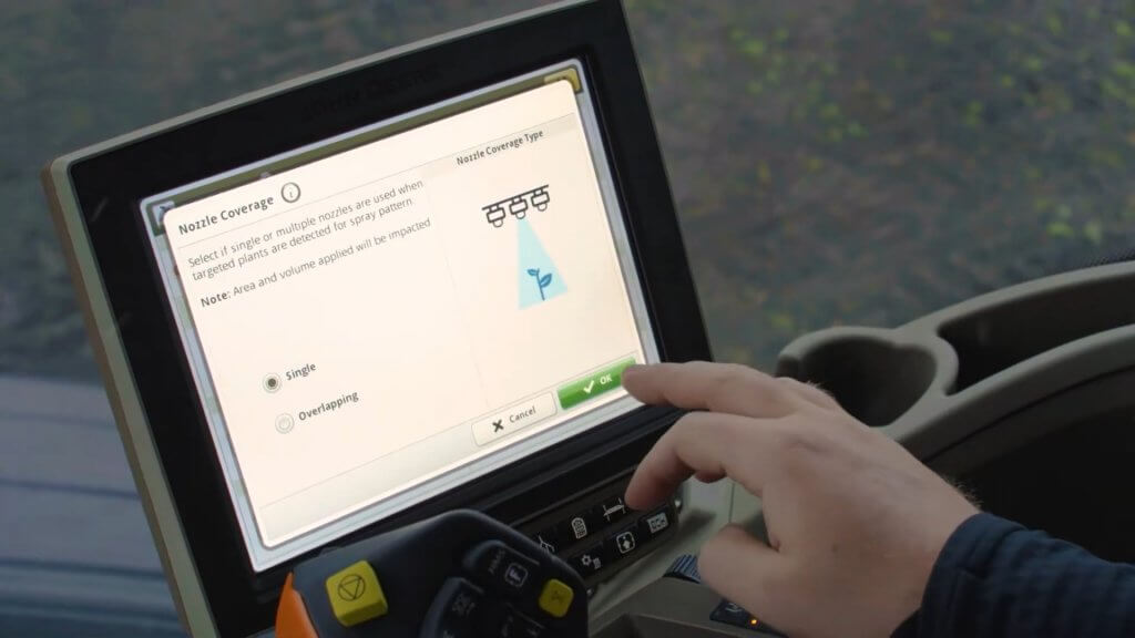
The pixels in the See & Spray camera chip are mapped during its initial calibration, allowing the processor to know which nozzle to turn on. There are two user-selected modes. In “Single Nozzle” Mode, the system turns on as few nozzles as possible. If the weed is directly under a nozzle, just that nozzle is turned on. Should the weed be in between two nozzles, both will be turned on. In “Overlapping” Mode, a detection will turn on at least three, and up to six adjacent nozzles. This mode is intended for herbicides that contain specific nozzle recommendations on the label, such as dicamba. By fitting these tips on the spot spray location, the required overlap and subsequent coverage can be guaranteed to be compliant with that label, a unique feature of See & Spray.
The number of nozzles activated by a weed detection depends on the location of the weed relative to the nozzles, and the mode selected by the user (Image courtesy John Deere)
In all modes, the user can specify the distance before and after the detected plant that the nozzle will spray. This feature is useful when boom height varies or when travelling faster to provide extra assurance that the target will be covered by the spray. The boom height range for See & Spray is 26 to 47” (66 to 120 cm), and the maximum travel speed with nozzles pointed down is 12 mph.
Installation of a 40 degree angled adaptor allows sprays tom be emitted backwards, and increases the spray speeds to 16 mph due to the extra distance and time afforded the sensors andoin processors to make a decision.
See & Spray has a built in contingency for suboptimal conditions, for example when the boom falls outside its height range, or the nozzle speed (not tractor) exceeds the 12 or 16 mph maximum in a turn, or a light or sensor or processor fault occurs. Called “Fallback Mode”, the boom can be configured to shut off, or to go into broadcast mode (using the spot spray nozzles) at that time. These types of insurance are a necessary part of an OSS on the market today.
To prevent fallback mode from occuring unecessarily, operators often choose to reduce their tractor speed one or two mph to allow for yaw without triggering all the nozzles.
No OSS system is perfect. Tiny weeds, or those obscured from camera view by crop residue, may be missed. The contingency for WEEDit is “Combined Mode”, where the entire boom emits a broadcast spray at a user-determined fraction of the full dose, while still maintaining spot spray capability at the full dose when a detection occurs. The reduced dose is sufficient to control the smallest weeds, whereas the spot spray is emitted at the full label rate for the larger ones. This capability is made possible through Pulse-Width Modulation (PWM) control of each nozzle.
John Deere has developed a mode of its ExactApply system to create the same outcome. Called “A & B Mode”, the rear nozzle (B location on the ExactApply nozzle body) is being activated by See & Spray. The front nozzle (A location) can be asked to spray simultaneously over the entire boom width. By choosing a smaller nozzle, a fraction of the label rate can be applied as a broadcast while maintaining spot spray capability. The broadcast boom is pulse-width modulated and retains the swath control and turn compensation of ExactApply. This mode also makes it easier to ensure coverage of these smaller weeds by selecting a finer, wider (110 degree) angles spray on the broadcast boom, and retaining a coarser, narrower fan angle banding nozzle for the spot application. The spot spray does not use PWM, relying on conventional speed and pressure to ensure the correct rate.
If planning to use A & B Mode, a user would first need to decide if they will calculate the spot spray dosing on a single or a multiple activated nozzle system. If priorizing the single nozzle actiation, one would first determine the band width of that nozzle, and size the nozzle accordingly. The band width should be ar close to the nozzle spacing as possible to maximize savings. Say the sprayer has 15″ spacing, and the nozzle’s band width is 20″. Now, whenever multiple nozzles are activated, they would operate as a 15″ spacing and would over-apply 20/15 = 1.33, or 33%. Say you want to apply 15 gpa (you may need to boost the spot spray volume to allow you to cut that with the broadcast feature). You can do it with the band (and overdose when using multiple nozzles, or apply 15 gpa with the multiple nozzles, underdosing by 28% when a single nozzle is activated. Or split the difference.
The next step is to select the application rate of the broadcast. If you want to apply 30% of the spot spray rate using the broadcast nozzles, size these accrodingly to apply 5 gpa.
For band- and spot-sprays, the width of the spray pattern at the target height determines the dose, therefore careful selection is advised. A worksheet that shows boom heights at various fan angles and nozzle spacings is downloadable here. TeeJet and Hypro offer a selection of narrower flat fan tips, but none yet in a low-drift design. Other nozzles are in development. Agrotop has already developed a low-drift “Spot Fan”, and MagnoJet, a Brazilian ceramic nozzle supplier, has 30 and 40 degree low drift tips for sale. Wilger has develped the DX series ComboJet tips in 20, 40, and 60 degree fan angles, in a low drift (pre-orifice design that works with PWM.
The camera sensing threshold can be adjusted to optimize a specific target. For example, to specify a certain weed size, that weed can be held in view of the sensor and the user can adjust the sensitivity until the weed is properly detected. As with any higher sensitivity, this runs the risk of more false detections, resulting in over-application. But it gives the user some knowledge that an important weed stage is being targeted properly.
The See & Spray camera relies on ambient light conditions, and John Deere recommends it not be used within 30 minutes of dawn or dusk. Both WEEDit and WeedSeeker, in contrast, can operate under any light conditions.
One of the challenges of running a OSS boom is the unpredictable fluctuation in flow requirement, which can theoretically range from just a few nozzles spraying to the whole boom activated in less than one second. While this extreme example is rare, a sophisticated and fast-responding pressure-based flow capability is nonetheless required. WEEDit uses a Ramsay Valve into their units to handle this challenge, whereas John Deere is relying on its existing plumbing design.
As a factory install, the See & Spray is fully integrated into the Series 4 display and is tied into JD Link. As a result, it can generate a high resolution map that shows each spot spray activation, by nozzle. The agronomic utility of this capability is significant, as it provides a very high resolution plant density map. This capability is also inherent in WEEDit and most green on Green systems available..
See & Spray Select is a factory option and comes integrated into the 4600 series monitor (Image courtesy John Deere)
It’s no secret that I believe optical spot sprays represent the future of pesticide application (see here). And it’s great news to see John Deere enter the OSS area with a factory installed option. As an influential force in ag, it lends credence to the concept and will benefit all other companies vying for this space. As they say, a rising tide raises all ships.