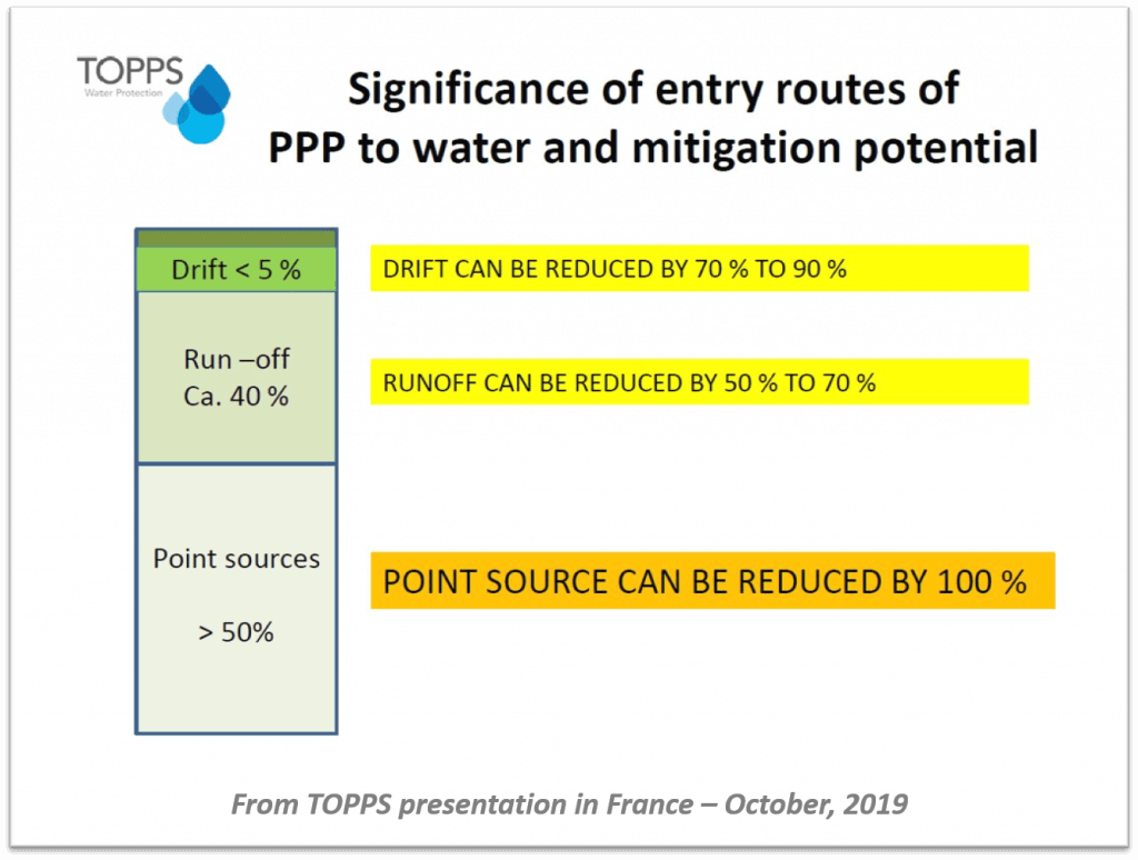
Spring always brings renewed interest in sprayer calibration. This is good, because a well-maintained and calibrated sprayer will protect crops more effectively and efficiently, as well as reduce the potential for off-target drift and point source contamination.
Presently, there is no nationally-recognized standard for sprayer calibration in either Canada or the United States. As a result there are many methods, some more stringent than others, spanning activities relating to seasonal maintenance through to precise diagnostic measurements. This means an operator can be in compliance with programs such as CanadaGAP (a food safety traceability standard for fruit and vegetables), and yet only perform the most rudimentary adjustments.
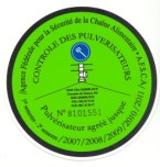
I was first made aware of “compulsory inspections” in 2009 when I started noticing certification stickers on certain European import airblast sprayers. Some Ontario tender fruit and grape growers familiar with the European standards asked why we didn’t enforce standardized calibration program as they do in Europe. I was surprised to hear a farmer ask for more paperwork, so it made me wonder, are Canada and the US overdue for a change?
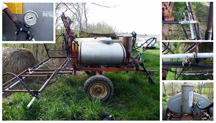
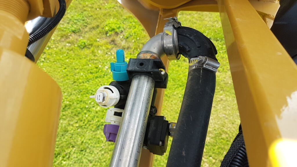
All sprayers, from large, commercial field and airblast sprayers, to the more humble home-grown sprayers (see below) benefit from regular servicing and calibration. And yet, sprayer calibration in Canada and the US remains largely voluntary and highly variable depending on the size of the operation, sprayer design and the willingness/skill of the operator.
Canada and the US: Then
In the mid 1980’s, University of Nebraska engineers and Successful Farming Magazine published a study showing that un-calibrated spray applications were costing US farmers ~$1,000,000,000 per year. The article was infamously called “The Billion Dollar Blunder”. You can download the original journal article describing the survey here. It was estimated that fewer than 5% of applications were within 5% of the desired rates. Spray overlaps and poor calibration resulted in over-applications of more than 20%.
At the time it was eye-opening and received a lot of attention. In 2006 the original study was revisited (see here), and even with advances in precision application, there was a disappointing lack of improvement. Bill Casady, University of Missouri Extension agricultural engineer, estimated that if 20 minutes of calibration can save 5% on 500 acres in an application sprayed at $25/ac ($61.75/ha), then the 20 minutes of effort worked out to $1,875 / hour. Now that’s a solid return on investment!
Belgium: Then
Belgium recognized and addressed this issue more than twenty years ago. In 1995, following the lead of the Netherlands and Germany, Belgium’s Ministry of Agriculture mandated that all spraying equipment (save backpacks) be inspected every three years. At the time, other countries such as Sweden, Hungary and Austria had similar, albeit voluntary, programs.
Belgian farmers received letters asking them to make their sprayers available for testing by a Ministry-appointed institution, in locations no more than 10 kilometers from their operations. The institution’s trained technicians would subject the sprayers to a regimented, standardized inspection. When the equipment met the standard, they would receive a permit in the form of a sticker (see below) attached to the sprayer. The growers paid for this service, based in part on the size of the sprayer.
In order to introduce the process to the Belgian farmer, a short documentary was produced. If you would rather not watch the preamble explaining why the prudent use of chemistry is critical to agriculture, and get right to the sprayer inspection process, skip ahead to 3:35.
What follows is a brief outline of that 1995 process, which I’m told is similar to the process currently used in Belgium:
Administrators perform visual checks to assess the general condition of the sprayer (e.g. obvious maintenance, safety and operational issues).
Boom balance (where applicable), hinges, boom ends and boom sturdiness is checked.
Nozzle spacing and orientation of nozzle bodies is inspected.
All points of filtration are inspected.
For boom sprayers, a spray pattern distribution used to be performed, but it wasn’t diagnostic enough. Instead, a pressure gauge / nozzle combo is used in each position to check for pressure fluctuation, and to ensure each tip had a flow rate within 5% of the average and no more than 10% deviation from the manufacturer’s rate.
For airblast sprayers, the overall output of the sprayer is measured to determine nozzle wear using individual collectors clamped onto each position.
For sprayers with rate controllers, calibrated collection bags are attached to a few nozzles and the sprayer drives a 100 metre course while spraying. The actual output is compared to the expected.
Finally, the farmer receives a report outlining issues that need to be remedied before the sprayer is certified.
SPISE: Today
Today, collaborating European countries are members of SPISE – Standardized Procedure for the Inspection of Sprayers in Europe. Established in 2004 by founding members from Belgium, France, Germany, Italy and the Netherlands, the SPISE Working Group aims to “further the harmonization and mutual acceptance of equipment inspections”. They also work to continually improve the inspection / calibration process.
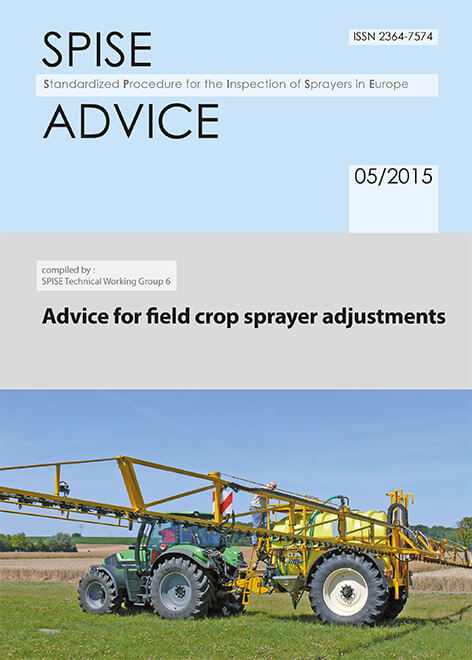
Their website hosts a number of sprayer-related resources, but the SPICE Advice handbooks are perhaps most valuable to the sprayer operator. Click either image below to download them as PDF for airblast or field sprayers:
This more current video by AAMS-Salvarani goes though the inspection and adjustment process for airblast sprayers. While there is no mention of air speed adjustments, many of the steps in this video correspond with the airblast adjustments relating to Crop-Adapted Spraying which has proven very successful in Canada.
Canada and the US: Tomorrow
Regular, third-party mediated inspections offer many potential benefits to the average operator. But, in order to realize gains in crop protection and environmental stewardship, perhaps there are two programs required: One to certify the sprayer and the other to certify the sprayer operator.
A sprayer inspection program would focus on sprayer maintenance rather than calibration. Maintenance occurs at regular intervals to ensure spray equipment is operating optimally. Calibration is an ongoing process intended to match the sprayer to the conditions in which it’s operating, and that requires an educated sprayer operator.
Sprayer operator education programs such as Ontario’s Grower Pesticide Safety Course, or Penn State’s Pesticide Applicator Certification Course already exist, but they are not offered in every state or province, and they are often voluntary or perhaps specific to a particular expertise (e.g. not applying to custom applicators or airblast operators).
They could start as voluntary, pay-for-service pilot programs to see if operators appreciate how much better their sprayers are functioning, and to quantify how much waste is been reduced. They wouldn’t necessarily have to be government-run; Industry or Academia may be better conduits. So, what would be required to develop and implement these two programs?
We would need to agree on a robust and generic sprayer inspection protocol. We have several European examples to draw on.
We would need to agree on the minimal content for a sprayer operator course. Again, we have many to draw on, with the obvious understanding that the core curriculum would be amended to reflect various state and provincial requirements.
We would need a trained, third-party organization to take responsibility for overseeing and implementing the two programs.
And, of course, we would need the funds to initiate both programs before they would eventually become self-sustaining.
So, are we dreaming in Technicolor? If responses to this article are any indication, there are those in western society that lash out at the idea of mandatory requirements. But there are supporters, too. Maybe we can learn from those European countries that have been doing this for more than 20 years.
Thanks to Jan Langenakens of aams for reviewing this article, and providing the videos.
Waste (noun): an act or instance of using or expending something to no purpose.
In agriculture, environment and economy are intertwined. Producers strive to obtain the maximum return on their inputs. They study incremental returns and avoid applying more inputs than necessary, especially if conditions don’t warrant it. The financial incentive is powerful, and waste is a four-letter word. This applies to seed, fertilizer, and pesticide. Pesticide labels identify the rate needed to obtain the desired result, and there is no incentive to over-apply. In fact, it’s illegal.
But there are plenty of other places where applications incur waste. As with time efficiency, it’s a good idea to identify where this waste occurs, and the only tool needed is a sharp pencil.
When might we incur waste in the spray application process?
Mixing more than we need because we don’t trust the flow meter or the tank gauge entirely, or don’t know the exact field size.
Priming the boom before the first swath.
Overlapping due to curvy terrain and coarse sectional control.
Spray drift away from the intended swath.
How big are the losses?
Let’s say we have a clean sprayer and need to spray 160 acres before moving to a new crop and product. We plan to apply 10 gallons per acre and have a 1,200 gallon tank with a 120 foot boom. That means we need 1,600 gallons of spray mix in total.
Once we’re at the field we prime the boom. Each sprayer is different, but depending on operator experience, 30 to 50 gallons are usually needed to push product from the tank to the last nozzle. Only part of that is lost to the ground, as boom sections can be shut off as soon as product has reached every nozzle of that section. We’re assuming 0.2 gallons per foot of boom is lost.
Spraying itself is relatively straightforward. Swath and sectional control handle the overlaps, but in less ideal terrain, double application is known to account for 4 to 5% of the area to reach non-square parts of the field. This is even more likely when the outer section is 10’ or more. Early turn-on of the boom prior to leaving the headland, to allow boom to reach operating pressure, adds to this.
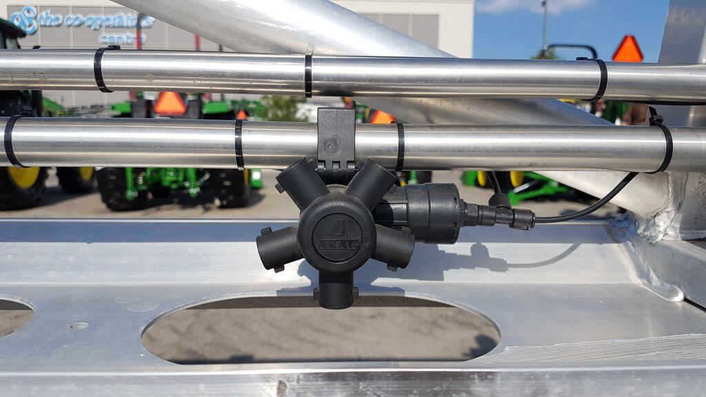
Air-activated shutoff for individual nozzles reduces section size at a reasonable cost.
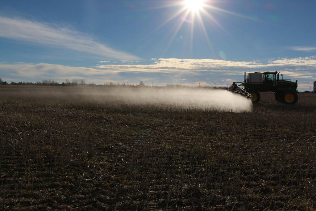
With an average nozzle, we can expect about 2% of the product to airborne drift. Most airborne won’t return to the ground within the field borders, so it’s a complete loss.
Most of the spray that travels more than 5 m after leaving boom stays airborne and should be considered a total loss from the field.
As we finish, the pump will draw air before the tank is empty due to sloshing or foaming, and a 50 to 60 gallon remainder may not be unusual. This simulation has assumed 5% of tank volume remains.
We also need to purge spray from the boom at cleanout, consuming approximately 0.4 gallons per foot of boom. This occurs after the field is completely sprayed and is therefore considered waste.
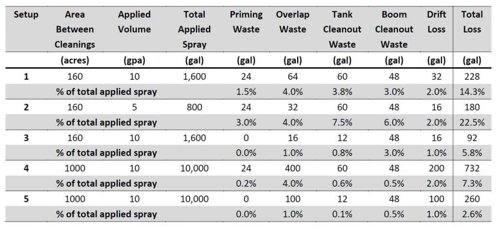
So how does this add up? The following table shows the approximate losses associated with five setups.
Table 1: Spray mix losses during a sprayer operation. Setup 1 = baseline, Setup 2 = low application volume, Setup 3 = baseline with recirculating boom, tank level monitor, and low-drift nozzles, Setup 4 = large area between cleaning, Setup 5 = large area with recirculating boom, tank level monitor, and low-drift nozzles.
In the first scenario, we spray just 160 acres at 10 gallons per acre. Priming the boom with 0.4 gallons per foot (allowing for all associated feed lines) consumes 48 gallons, but only wastes half of that, or 1.5% of the total volume needed for the field.
Four percent overlap consumes another 64 gallons.
If we have 5% of the tank volume left over, that’s 60 gallons. That amount is so small it doesn’t even register on the sight gauge but nonetheless it represents another 4% of the total sprayed amount.
Upon cleaning the boom, we need to push the spray mix out of all the plumbing after the pump, as it has nowhere else to go. At an assumed 0.4 gallons per foot, that’s another 48 gallons or 3%.
If we add to that a conservative 2% drift loss, it sums to a surprising 14% of the total spray volume. For those that use lower water volumes (the second scenario), the volumetric losses are slightly less, but their proportion is higher, now accounting for 23% (!) of the total spray mix.
In the third scenario, let’s assume we use a recirculating boom that returns the initial prime volume to the tank, eliminating any waste. We’ll also upgrade to individual nozzle sectional control, reducing overlap to 1%. And, since we want to know exactly what’s left in the tank, let’s invest in an AccuVolume system to precisely monitor tank volume. This allows us to make small rate adjustments up or down to be sure as much of the mixed product goes onto the sprayed swath as possible.
Recirculating booms allows the spray mix to pass through entire length of boom without being sprayed, saving waste during priming and allowing waste-free boom rinses.
When the sump begins to empty, we can introduce some water from the clean water tank to push the last of the mix to the boom (a continuous rinse system makes this easy).
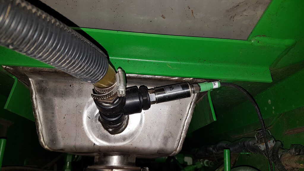
An AccuVolume sensor shows the exact volume left in the tank at any slope position and with 1 gallon resolution, allowing greater accuracy when filling and emptying.
We’ll assume our sump waste is now reduced to 12 gallons. We still need to dispose of the content of the boom somehow, so the recirculating boom offers no saving there. But let’s also add better low-drift nozzles to reduce drift by 50% (now 1% total volume). Total loss is now just 6%.
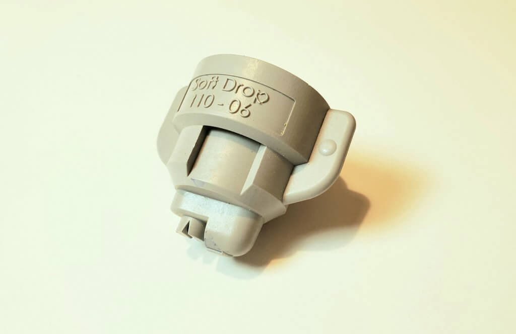
Low-drift nozzles such as this AirMix (Agrotop) SoftDrop reduce airborne drift by 50 to 90%.
The last two rows in the table repeat the first and third scenarios for a larger sprayed area (1000 acres) before a tank cleaning is needed. This doesn’t change the magnitude of the volumetric loss, but reduces its proportion. Percent loss is down by a factor of two from the 160 acre interval, to 3 to 7%.
Experienced operators might cheat the system a bit by mixing the required pesticide with some extra water to make up for the plumbing waste. Doing so prevents extra pesticide from being consumed, but it doesn’t reduce the inherent inefficiency.
Lessons
This exercise suggests that waste from spraying is probably higher than we assumed. If we average the scenarios, there is 10 to 15% waste. At, say, $200,000 spent on pesticide for a single spraying season, that’s $20 – $30,000 worth of product and water hauled that ends up where it doesn’t belong. Beyond the time and money, there can also be environmental consequences depending on how that waste is treated.
Improve monitoring of tank content to allow lower remainders.
Consider individual nozzle shutoff to improve sectional control. These are part of Pulse Width Modulation (PWM) systems, but can also be achieved with less expensive valves.
Plan spray operations to minimize the amount of product changeovers.
Consider direct injection.
The return on investment for plumbing improvements can be high and result in considerable future savings over the life of the sprayer. It’s worth thinking about.
When I had to replace a pump on a small scale sprayer, I had a lot of questions about how they worked, their capacities, hose sizes, mounting solutions and fittings. I turned to the Pentair Hypro Shurflo catalog and found a very helpful guide on pages 2 – 10. This article summarizes the steps recommended in the catalog.
Select Pump Style
Sprayer pumps can be divided into two categories: Positive Displacement Pumps and Non-Positive Displacement Pumps.
Positive Displacement Pumps
These include Roller, Diaphragm and Piston pumps. They are self-priming and traditionally operate at high pressures. Flow from these pumps is directly proportional to the pump speed, which is why they require a relief valve and bypass line between the pump outlet and the nozzle shut-off valve.
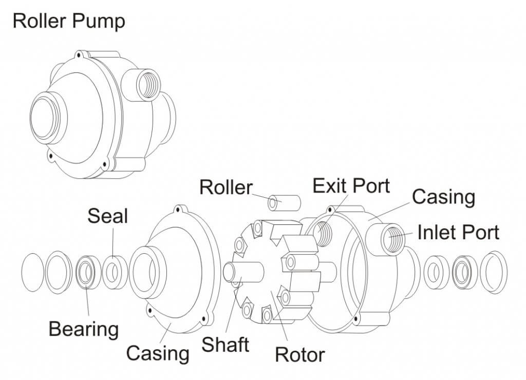
Roller pumps : This is the most popular pump with farmers world-wide. The seal and roller materials should be selected based on their compatibilities with the pesticides.
Diaphragm pumps : These compact pumps are popular for use with abrasive and corrosive pesticides. Their oil-filled piston chambers protect the pump materials.
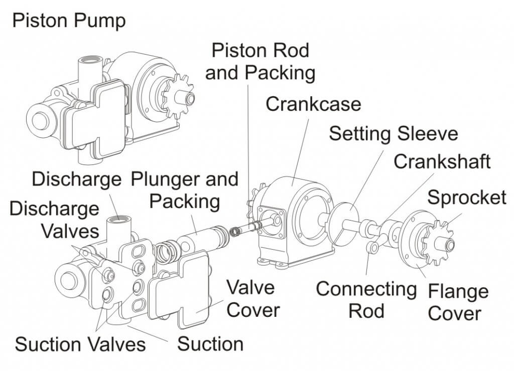
Piston pumps : Similar to car engines, these pumps are relatively low-flow and high-pressure and suited for use with handguns sprayers. The piston cup materials should be selected based on their compatibilities with the pesticides.
Non-Positive Displacement Pumps
These include Turbine (or Transfer) and Centrifugal pumps. They must be primed and traditionally operate at low to medium pressures, although there are models available that can go up to 190 psi. Flow from these durable pumps comes from a rotating impeller that feeds liquid through the lines instead of pumping “per stroke”. Therefore, if the outlet is closed for brief periods, the impeller spins harmlessly, so a relief valve is not needed.
Determine PTO Pump Drive
When selecting a pump, you must specify the shaft rotation. Hypro suggests two steps for determining the required rotation:
Eyes on the End: Face the rotating Power Take-Off (PTO) and determine if it is spinning clockwise (CW) or counter-clockwise (CCW).
Opposites Attract: The pump must rotate opposite to the PTO. For example, if the PTO rotates CW, then the pump must rotate CCW and vice versa.
You should also be aware of your tractors’ horse power, and in order to determine the size of pump shaft, you should know the spline dimensions (e.g. 1-3/8″ (6 spline) pto shaft or 1-3/8″ 21-spline pto shaft).
Determine Pressure and Flow Requirements
In order to size the pump, you have to know the sprayer settings, such as intended application rate, average ground speed, agitation requirements, etc. Most can be calculated form the following formulae (provided in US and Metric units):
Calculating Agitation Requirements
Liquids :
Tank Volume (US gal.) × 0.05 = Agitation Requirement (gpm) Tank Volume (L) × 0.05 = Agitation Requirement (L/min.)
Wettable Powders and Flowables
Tank Volume (US gal.) × 0.125 = Agitation Requirement (gpm) Tank Volume (L) × 0.125 = Agitation Requirement (L/min.)
If the sprayer has a hydraulic agitation system equipped with a jet, it multiplies the agitation output without the need for additional flow. For example, it might have a 1 gpm input flow and boost it to a 10 gpm output. This savings should be accounted for:
Therefore, if you calculate a 60 gpm requirement for agitation, and have a jet that boosts the output 3:1:
60 gpm x (1 / 3) = 20 (gpm)
Calculating Nozzle Requirements
Once the agitation requirements are accounted for, you have to account for nozzles. The calculations are a little different for each sprayer, but they amount to the same thing – Total flow in US Gallons per minute or Litres per minute. Here is the calculation for a boom sprayer. For an airblast sprayer, assuming you are spraying every row, substitute “Row Spacing” for “Boom width”.
Total Flow Requirement (gpm) = [Output (gpa) x Ground Speed (mph) × Boom width (ft)] ÷ 495
Total Flow Requirement (L/min.) = [Output (L/ha) x Ground Speed (km/h) × Boom width (m)] ÷ 600
When the flow requirement for agitation and the flow requirement for the nozzles have been calculated, they are added together. It is important not to under-size the pump, so always factor in an extra 20% to compensate for changes in performance (such as pump wear and slower ground speeds) and restrictions in the plumbing systems that can cause pressure drops between the pump and nozzles, as follows:
Finally, be sure to account for any other flow requirements, such as tank rinsing nozzles and hose length/diameter (which causes pressure drops), and have some idea how you want to place the pump relative to the tractor and sprayer. If you prepare all this information, you can quickly and easily discuss your options with the retailer and select the pump that best suits your needs.
For more information on various types of pumps, check out this article by Dr. Bob Wolf:
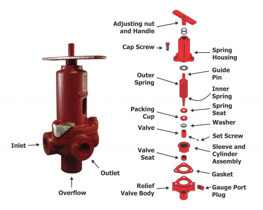
A properly-sized pump should produce more flow than is needed and work in conjunction with the atomizers to regulate that flow. Typical to high pressure pumps, a piston relief valve (aka regulator) should maintain the desired system pressure through the normal speed range of the sprayer, regardless of the number of booms (or boom-sections) that are on or off. This is achieved by balancing the sprayer pressure against the relief valve spring, which must move freely across a range of flows.
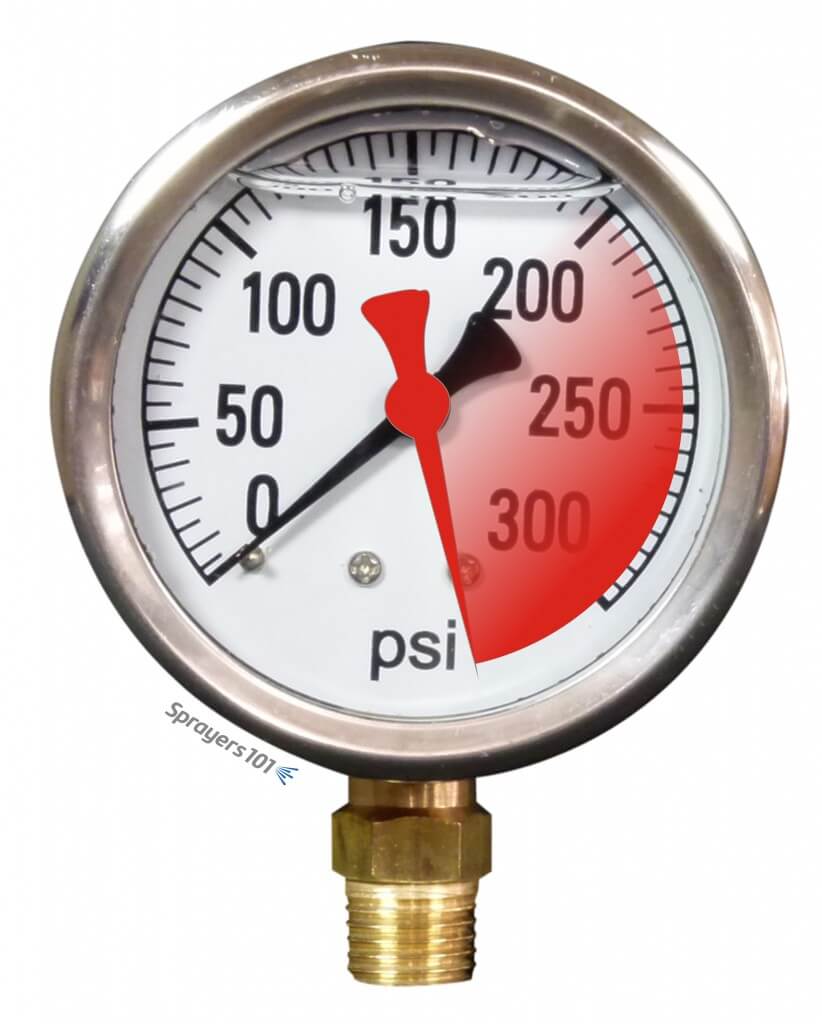
But what does it mean when the pressure gauge briefly spikes off-scale when boom are turned on or off? This is bad for the gauge and will eventually cause it to fail. Quite often, pressure spikes are an indication of one of two things:
A dirty or stuck valve
An inappropriate spring size
A pressure gauge spiking beyond its range.
Relief valve maintenance
Sometimes, pressure spikes indicate a need for valve cleaning and maintenance.
The regulator spring cavity may be packed with dirt, which limits valve travel. Clean the housing and spring, and then lubricate and adjust.
The regulator may be partially seized or sticky. If the regulator piston and cylinder bores are caked with spray they will ‘hold’ the valve until the pressure/spring balance overcomes the friction.
Sometimes valve, and/or the valve guide pin are seized. Disassemble them, clean all sliding surfaces, then lubricate and adjust.
Valve/seat wear may have created a leak. You may have already tightened the spring to compensate, but this loads the spring past the pressure balance point you want to spray at. This means that when the booms are shut off, the pressure increases until it reaches the ‘new’ spring balance point. Repair (or replace) the regulator, then lubricate and adjust. Be aware that any leak (external or internal) can contribute to this condition and tightening the spring isn’t the solution.
The spring may be damaged (e.g. bent, corroded, etc.). Replace the spring, lubricate and adjust.
Note: Be sure to read the operator’s manual before you do anything. You should understand your sprayer’s design before you perform any maintenance, adjustments or calibration.
Spring size
Sometimes, the relief valve may be mechanically sound, but the spring may not be sized to match a reduced operating pressure. Relief valve springs match the maximum pressure range of the pump. Sprayers operated at lower pressure may be unable to compress the spring. This is common when people switch from disc-core nozzles operated at higher pressure to molded nozzles operated at lower pressure.
This would manifest when one boom is shut off for single-boom operation; there may not be enough pressure to open the bypass. As a result, flow increases over the remaining boom.
Recognizing this problem, some operators have teed-in a second relief valve capable of finer adjustments at lower pressures. Make sure you know what you’re doing if you’re considering this option.
Technically, a spring can either be too weak, or too heavy:
The spring may be too weak for the pressure being used (i.e. any adjustment bottoms out). In order to obtain sufficient pressure the operator tightens the spring until it is virtually collapsed, essentially creating a fixed orifice. When the booms are closed the ‘fixed orifice’ doesn’t compensate and pressure rises to force the increased flow through that small orifice.
If the spring is too heavy for the pressure being used (any adjustment barely touches the spring when pump is turned off). In this case, the pressure being used will not deflect the spring, so the operator closes the regulator until the ‘fixed orifice’ creates sufficient restriction to flow to achieve the desired pressure. When the booms are closed the ‘fixed orifice’ doesn’t compensate and pressure rises to force the increased flow through, or until the spring begins to deflect.
In either situation the spring must be sized so it is in the centre-third of its flex range (i.e. rest state > fully collapsed) at the desired pressure. You can buy springs from the sprayer dealer or hardware supply. Try to maintain original length and diameter of the coil, while varying the diameter of the wire.
Engineering
In some cases, it is not a matter of valve maintenance, or spring size, but poor engineering. Consider the following:
The valve supply and return may be too small for the pump flow. Consult hose and fitting catalogs for flow capacities and lengths. Re-size the hoses and fittings appropriately, and then adjust the regulator.
There may be kinks or sharp bends in in the supply and return lines. Re-route the hoses and/or fittings to avoid kinks and sharp bends, and then adjust the regulator.
The relief valve may be too small for the pump flow. Consult a regulator catalog for flow capacities and replace the regulator with an appropriate size. Calibrate the regulator spring and adjust.
Relief valves have a ‘cracking’ pressure (that’s when the valve just starts to open). Well-designed regulators have small pressure changes from ‘cracking’ to full flow. That information is in their catalogs. Poorly designed regulators have large pressure changes between these two ratings and these regulators should be avoided.
The pump may be too big for system. This often happens when sprayers are upgraded and pumps are replaced. Consult the catalogs and reduce pump size or speed, or increase the sizes of the hoses, fittings and regulator.
There may be a hydraulic agitator jet on the regulator ‘tank’ line. An agitator jet applies considerable back pressure to a system, and when booms are closed the increased flow causes more than a linear increase in pressure.
Broadly, the sprayer system as a whole may be poorly engineered. Inspect and draw a flow path of the sprayer system. Examine where everything is going (or not going). Is it possible someone made changes that the manufacturer did not intend? Consult the manufacturer if you are uncertain. Sometimes, it will have to be re-engineered, which may require expert consultation.
Note: Your pressure gauge can tell you a lot more than your operating pressure – it can indicate a problem with your regulator, pump, lines or overall sprayer engineering. Don’t ignore it – address it.
Thanks to Murray Thiessen, Consulting Agricultural Mechanic, for his contribution to this article.
The pump is the heart of the sprayer and a key component for producing the flow of spray material and sprayer output. Because various spraying situations require different pressures and flow rates, using the correct sprayer pump is essential to achieving desired results. In addition to sprayer considerations, a pump must also be durable enough to withstand harsh chemicals that may cause excessive wear. Even though pumps with added chemical corrosion protection are more expensive, they are a popular choice because of their durability.
Roller, centrifugal, diaphragm, and piston pumps are commonly used to apply crop protection products. Centrifugal and roller pumps are typically used for low-pressure sprayers, and diaphragm and piston pumps are more popular when high-pressure sprayers are needed (i.e., vegetables, orchards, etc.). Less common pump types include squeeze, gear, and turbine.
Pumps are typically either ground driven or powered by main or auxiliary engines, power takeoff (PTO) shafts, or hydraulic pumps. The choice of pump depends on the material to be pumped and the capacity or volume needed. However, no particular type of pump is ideal for all purposes.
Sprayer pumps can be divided into two general categories: positive displacement and non-positive displacement. Positive displacement pumps (roller, diaphragm, and piston) maintain a flow output directly proportional to the pump speed. These pumps require a pressure-relief valve and a bypass line for proper performance. Non-positive displacement pumps do not have a proportional output flow to pump speed and do not require a relief valve and bypass line. The centrifugal pump is an example of a non-positive displacement pump style. A summary of common pump types and characteristics is found in the following Table (contributions from ACE Pumps Corporation, Hypro Pumps Inc., and CDS-John Blue Company).
Characteristic
Roller
Centrifugal
Diaphragm
Piston
Ground Driven Piston
Cost
Low
High
Medium
High
High
Displacement
Positive, self priming; Requires relief valve
Non-positive, needs priming; Relief valve not req’d
Positive, self-priming; Requires relief valve
Positive, self-priming; Requires relief valve
Positive, self-priming; Relief valve not reg’d. Runs off drive wheel and can be lifted on hydraulic-controlled applicators, or can be purchased with clutches to to disengage pump when flow is not desired.
Drive Mechanism
PTO, gas engines, electric motors
PTO, hydraulic drives, gas engines, electric motors
PTO, hydraulic drives, gas engines
PTO, gas engines, electric motors
Primarily ground-driven. Although less common, can be used with hydraulic drives, electric motors or gas engines.
Adaptability
Compact and versatile
Good for abrasive materials; Handles suspensions and slurries well.
Compact for amount of flow and pressure developed.
Wide range of spraying applications; Dependable
Wide range of spraying applications from clear liquids to suspensions. Very accurate regardless of ground speed or back pressure. Very dependable.
Durability
Parts to wear; replace
Very durable, not much wear
No corrosion of internal parts
Parts to wear; replace
Very durable. With basic care and maintenance, pumps can easily be in service 30 years or more.
Serviceability
Easy to work on, repair
Basic maintenance extends life
Low maintenance
Potential for high maintenance
Low maintenance
Pressure Range
up to 300 psi
up to 180 psi
up to 725 psi
up to 400 psi
up to 120 psi
Output Volume
2 to 74 gpm; high volumes for size; proportional to pump speed.
up to 190 gpm; High volumes for size and weight; Proportional to pump speed.
3.5 to 66 gpm; Proportional to pump speed.
up to 10 gpm; Proportional to pump speed, independent pressure.
0.5 gpm to 68.4 gpm.
Revolutions per minute
540, 1000
Requires speed-up mechanism. Very efficient at higher speeds; up to 6,000 rpm.
540
540
Ground-driven. Maximum 450 rpm.
Notes
Best choice by farmers.
If hydraulic-driven, no PTO required. Popular in commercial ag. applications. Running pump dry i s a problem.
Good for higher pressure requirements. Popular for horticultural applications. Pump can run dry.
Similar to an engine; Low capacity.
No gpa flow variation due to pressure or ground speed changes. No concern of electric failures on controllers or radar systems. Dependable accuracy.
Pump Efficiency
Regardless of the type of pump, the necessary flow rate must be provided at the desired pressure. Enough spray liquid should be pumped to supply the gallons per minute (gpm) required by the nozzles and the tank agitator, with a reserve capacity of 10 to 20 percent to allow for flow loss as the pump becomes worn. Unfortunately, pumps lose efficiency for a number of reasons, such as drive friction or leakage.
When estimating the pump horsepower needed for an application, efficiency (Eff) of 40 to 60 percent should be assumed. The horsepower (HP) required to drive the pump can be estimated by using the following formula:
HP = (gpm × psi) / (*1,714 × Eff) *Constant derived when converting gallons, minutes, pounds, and inches to horsepower.
Example: How much horsepower is required to run a pump if the maximum output is 50 gpm at 40 pounds per square inch (psi)? Assume a pump efficiency of 40 percent.
HP = (50 gpm × 40 psi) / (1,714 × 0.40 Eff) HP = 2.92
Because of inefficiencies of the drive units, electric motors should be approximately one third larger than the calculated horsepower. Gasoline engines should be one half to two thirds larger than the pump horsepower required. Ground-driven pumps that vary flow rates as ground speed changes are accurate and dependable; they are often used when applying high volumes of materials such as fertilizer.
Many pumps are PTO driven, but most modern spray pumps are hydraulic driven because of mounting versatility, ease of maintenance, and customization for individual sprayers. Charts are available to match pumps to various tractor hydraulic systems. You can access these charts by following the links to the following major pump manufacturers:
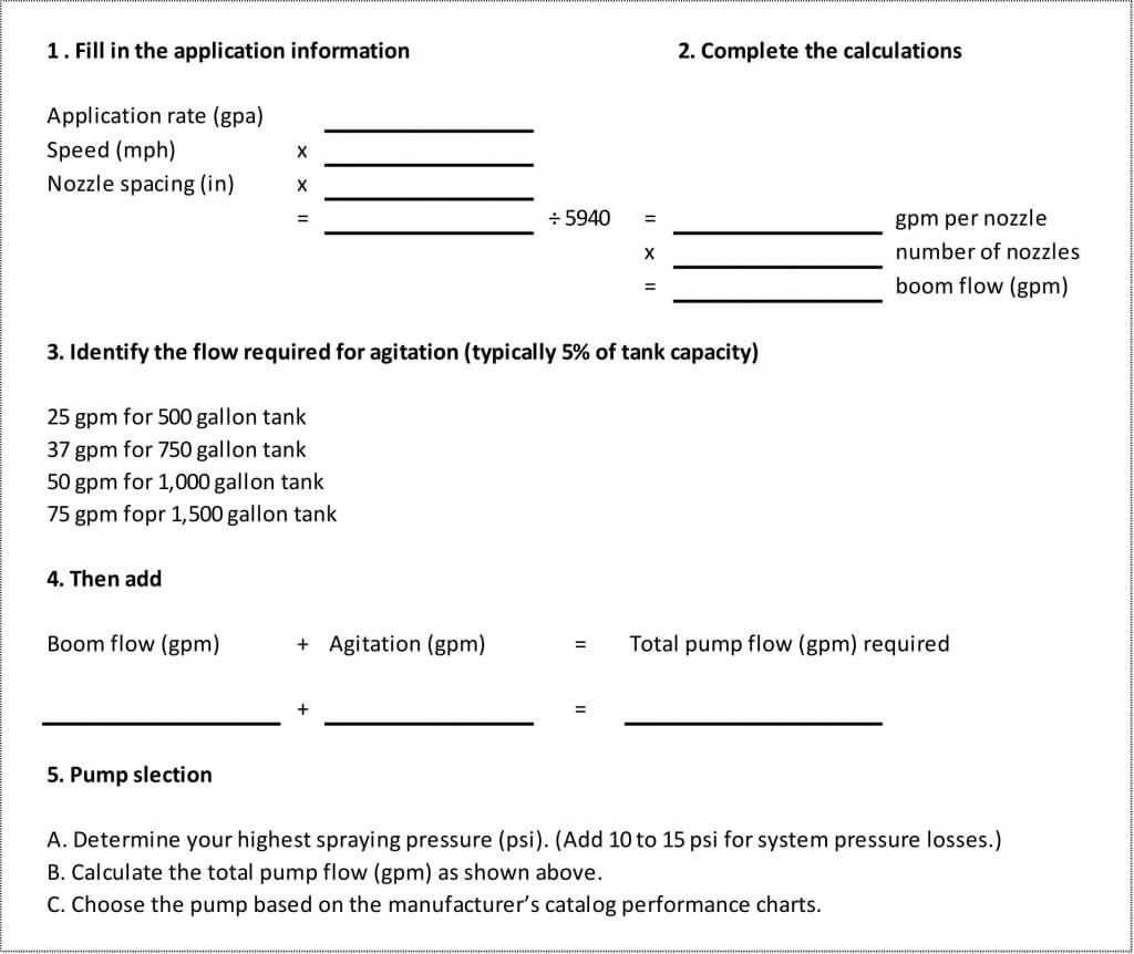
Proper pump size is an important consideration when selecting a sprayer pump. Requirements for nozzle capacity, hydraulic agitation, and overcoming the efficiency loss noted previously are essential points to consider. Nozzle capacity is determined by multiplying the number of nozzles on the boom times the output (gpm) of each nozzle for a specific application. Be sure to give consideration to the range of spray pressures that will be used for the given application. Agitation requirements typically account for another 5 percent of the sprayer tank capacity. Efficiency losses due to friction and pump wear may account for an additional 10 to 20 percent increase in the required flow rate. Spray pump manufacturers provide useful Web page worksheets to help determine pump sizes based on typical field application scenarios.
Manufacturers also make product guides available to help match sprayer pumps and hydraulic motors to the tractor’s hydraulic system (Table 2). A simple pump selection worksheet is provided at the end of this article.
No matter what type pump is used, it must be plumbed to route liquid from the pump to the spray boom with a minimum amount of restriction, a necessity for achieving the pump’s maximum rated capacity. The hoses should be the same size as the pump’s suction and discharge ports. Other recommendations include installing a pressure gauge and valve on the pressure side of the pump to measure the shut-off pressure and using a minimum number of elbows, fittings, and valves to reduce pressure losses.
Following these guidelines is necessary for delivering the highest pressures to the boom.
Pump Rotation
Pump rotation is critical for PTO and belt and- pulley driven pumps. The direction of rotation is always determined when facing the pump and drive shaft, and pumps are available in both clockwise and counter-clockwise rotation. Thus, when direct coupling shafts, the opposite rotation pump should always match the shaft. When mounting a pump with belts and pulleys, either pump rotation can be used to match the drive shaft rotation and the desired direction of the pump. Gasoline engine and electric motor shafts rotate in a counter-clockwise direction, and a tractor PTO shaft rotates in a clockwise direction.
Pump Types
Roller pumps are popular for small sprayers because of their low initial cost, compact size, ease of repair, and efficient operation at PTO speeds of 540 and 1000 revolutions per minute (rpm). Roller pumps are self-priming, positive displacement pumps, and a variety of models is available. Maximum outputs range from 2 to 75 gpm, and pressures range up to 300 psi.
Figure 1 – Roller Pump
Roller pumps are usually constructed with cast iron or corrosion resistant housings (non-symmetrical in shape), rotors, four to eight rollers (either nylon, Teflon, or rubber), and seals (Viton, rubber, or leather). The type of material selected depends on the chemical being pumped. A typical roller pump is shown in Figure 1.
Nylon or Teflon rollers are the most resistant to agricultural chemicals and are recommended for multipurpose sprayers. Rubber rollers are preferred when the pump is used only for water solutions and wettable powder slurries at pressures less than 100 psi. Because sand and scale are abrasive to the rollers, the solution being pumped must not contain these materials. Polypropylene rollers wear better than either nylon or rubber rollers when applying weak solutions or solutions with little or no lubricating qualities.
Some operators have experienced problems with excessive wear of the rollers, especially when using wettable powders. Other operators have achieved long pump life by allowing the pump to run continuously when spraying with wettable powders, and by properly maintaining and storing the pump, including keeping abrasive materials out of the sprayer. Specific seal, roller, and casting materials can be selected for compatibility with certain herbicides, insecticides, fungicides, and fertilizers Consideration should also be given to the adjuvants used in the spray solution.
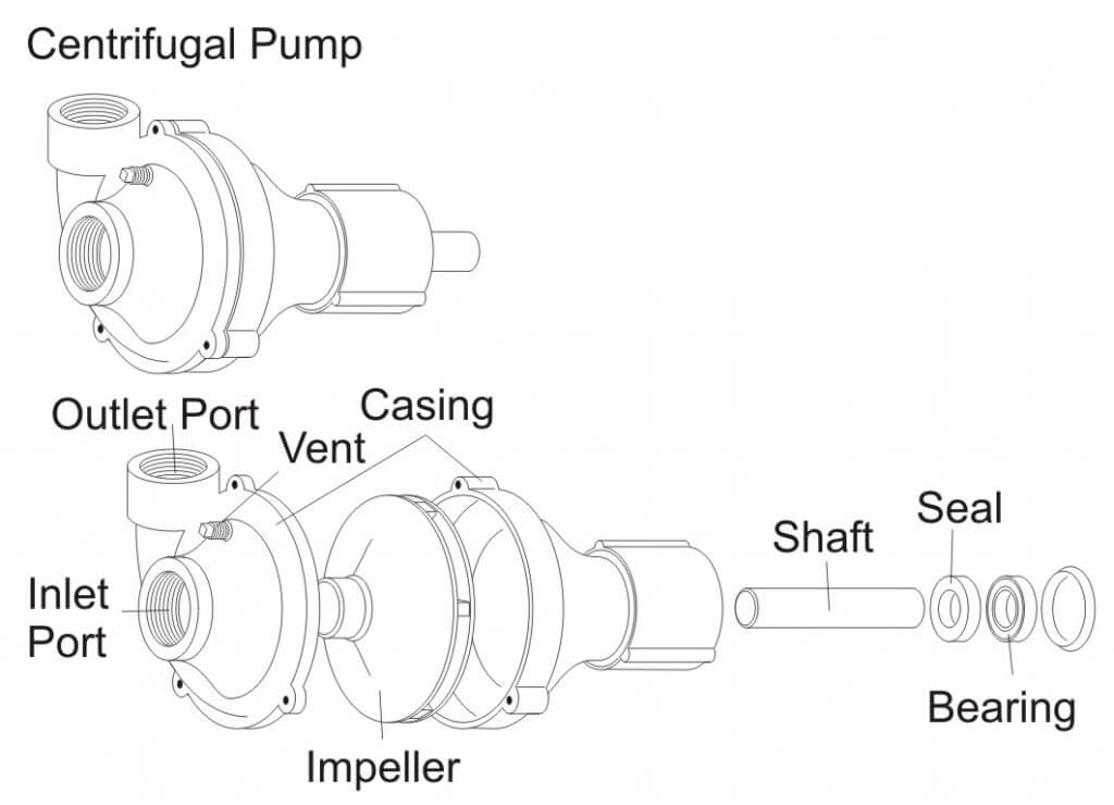
Centrifugal pumps are the most popular type of low-pressure sprayer. They are durable, simply constructed, and can readily handle wettable powders and abrasive materials. Because of the high output of centrifugal pumps (70 to 190 gpm), the spray solution can be agitated sufficiently even in large tanks at pressures up to 180 psi. The initial cost of a centrifugal pump is somewhat higher than that of a roller pump, but its long life and low maintenance make it an economical choice. Pump housings of cast iron, stainless steel, and polypropylene are advantageous because they withstand strong chemicals. Stainless steel pumps are ideal for use with glyphosate or other acid applications. Polypropylene pumps are lightweight and provide excellent resistance to corrosive chemicals. Figure 2 shows a typical centrifugal pump.
Centrifugal Pump – Exploded View.
Because centrifugal pumps are not self-priming, they should be mounted below the supply tank to aid in priming. In addition, a small vent tube should be installed from the top of the pump housing to the supply tank. This positive vent line allows the pump to prime itself by “bleeding off” trapped air upon starting and when the pump is not operating.
The inlet of a centrifugal pump should never be restricted. A partially clogged suction strainer, collapsed suction line, or a suction line with insufficient capacity causes a loss of pressure control and possible damage to the pump. Centrifugal pumps can handle small pieces of foreign material without damage, so a suction strainer is not always required. If a suction strainer is used, however, it must be capable of handling the large capacities of the pump with a minimal drop in pressure across the strainer, and it must be cleaned frequently. Typical centrifugal pump plumbing would place the strainer on the pressure side of the pump.
Centrifugal pumps for low-pressure sprayers can generate pressures of up to 70 psi when the impellers are running between 3,000 and 4,500 rpm. The output volume drops off rapidly when the outlet pressure exceeds 30 to 40 psi. The decrease in volume is an advantage because the nozzle pressure is able to be controlled without a relief valve. See Figure 3 for a typical centrifugal pump performance curve. The pump performance curve describes the relationship between flow rate and pressure for the actual pump.
Figure 3 – Centrifugal Pump Performance Graph
The need to operate at high impeller speeds requires a type of step-up speed mechanism when operating centrifugal pumps from PTO shafts. The simplest and least expensive of these mechanisms is a belt and sheave assembly. Other step-up mechanisms have planetary gears that are completely enclosed and mounted directly on the PTO shaft.
Another method of driving a centrifugal pump is with a close coupled, high speed hydraulic motor. Using the tractor hydraulic system to drive the pump keeps the tractor PTO shaft free for other uses. It is essential to consult manufacturer pump selection guides to match the proper pump to your tractor. Pumps can also be driven by direct-coupled gasoline engines when other drive mechanisms cannot be used.
Airplane pumps may be wind-driven, directly powered from the aircraft engine, or powered by an electric or hydraulic motor. The pump may also power the tank agitation system. For fixed-wing aircraft, the most common type of pump is a wind-driven centrifugal pump mounted under the aircraft (Figure 4). The propeller slipstream drives a fan mounted on the front of the pump. Some fan-driven pumps have variable pitch blades that allow for changing pump speed, and thus output. The centrifugal pumps commonly used on aircraft produce high volumes (up to 200 gpm) at typically low pressure, usually ranging between 10 and 100 psi. These pumps usually require operating speeds from 1,000 to 5,000 rpm.
Figure 4 – Airplane Pump
Diaphragm pumps are popular when higher pressures are needed for applying foliar herbicides, insecticides, and fungicides. Models are available that provide maximum outputs ranging from 3.5 to 60 gpm and maximum pressures ranging from 200 to 700 psi. These pumps are extremely durable because all moving parts are sealed in an oil bath and spray solutions. Diaphragm pumps are self-priming and considered positive displacement pumps. Figure 5 shows a typical diaphragm pump. Smaller electric diaphragm pumps (Figure 6) are available for use by homeowners, ranchers, and hobbyists to apply pest control products. A good example is a spray system mounted on an ATV for spraying pastures and rights-of-way.
Figure 5 – Diaphragm Pump
Piston pumps are positive displacement pumps that are favored by many users for their priming ease, higher pressure capability, and constant volume spraying. Piston pumps are often used to apply crop protection products and fertilizers in combination with a ground drive so that flow rate stays proportional to ground speed and application rates remain constant. A pressure relief valve is required, though. Figure 7 is an example of a piston pump used to accurately meter liquid fertilizers.
Figure 7 – Piston Pump
Turbine pumps are also available for low‑pressure sprayers. A turbine pump consists of a rotating turbine within an enclosed housing. These pumps are similar to centrifugal pumps, except they provide higher flow capacity and pressures of up to 70 psi when mounted directly on a 1,000 rpm PTO shaft, eliminating the need for step‑up mechanisms. Because of the close tolerances between the turbine blades and the casing, turbine pumps are better adapted for clean fluids of low viscosity but may have difficulty with wettable powders and suspensions. Figure 8 shows a typical turbine pump.
Figure 8 – Turbine Pump
Gear pumps are positive displacement pumps capable of providing a smooth, low-volume, continuous flow of material. Gear pumps are typically two gears meshing together revolving in opposite directions within a casing. Abrasive materials such as wettable powders rapidly wear the gears and pump housing. Figure 9 shows a typical gear pump.
Figure 9 – Gear Pump
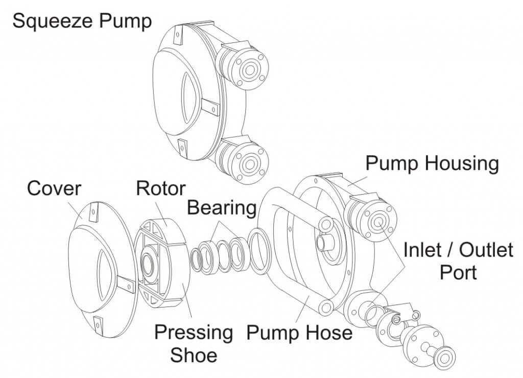
Squeeze pumps are low-pressure, positive displacement pumps with output proportional to speed. Pump flow is created when liquid is trapped by squeezing the hose between a roller and casing. Pump flow is determined by the size and number of hoses. This pump is ideally suited for metering small quantities of fertilizers or pesticides and would be practical for injection-type pumping systems. Figure 10 shows a typical squeeze pump.
Figure 10 – Squeeze Pump
Pump Maintenance
Proper pump maintenance is critical for maximum pump life. Regular cleaning is essential to removing all chemical residues and preventing wear to the pump from corrosive solutions. Do not allow spray solutions to remain in the sprayer for extended periods of time. Using lightweight antifreeze or a motor oil as the final spray solution after cleaning can preserve the pump during a period of non-use.
Pump Selection Worksheet
Acknowledgements
Excerpts for this article were adapted with permission from University of Illinois Circular 1192 developed by Loren Bode and Jack Butler (May 1981), Extension Agricultural Engineer and Professor of Agricultural Engineering, Univerity of Illinois at Urbana-Champaign. Contributions for this article were also received from ACE Pumps Corporation; Hypro Pumps Inc.,; and CDS-John Blue Company.
For more information on pump selection, check out this article.