“What is the right way to apply this pesticide?” It’s one of the classic questions. Applicators know that spray method determines the efficacy of the application as well as its environmental impact. And it has to use time and water resources efficiently to make sense.
To answer the question properly, we need to take things one step at a time.
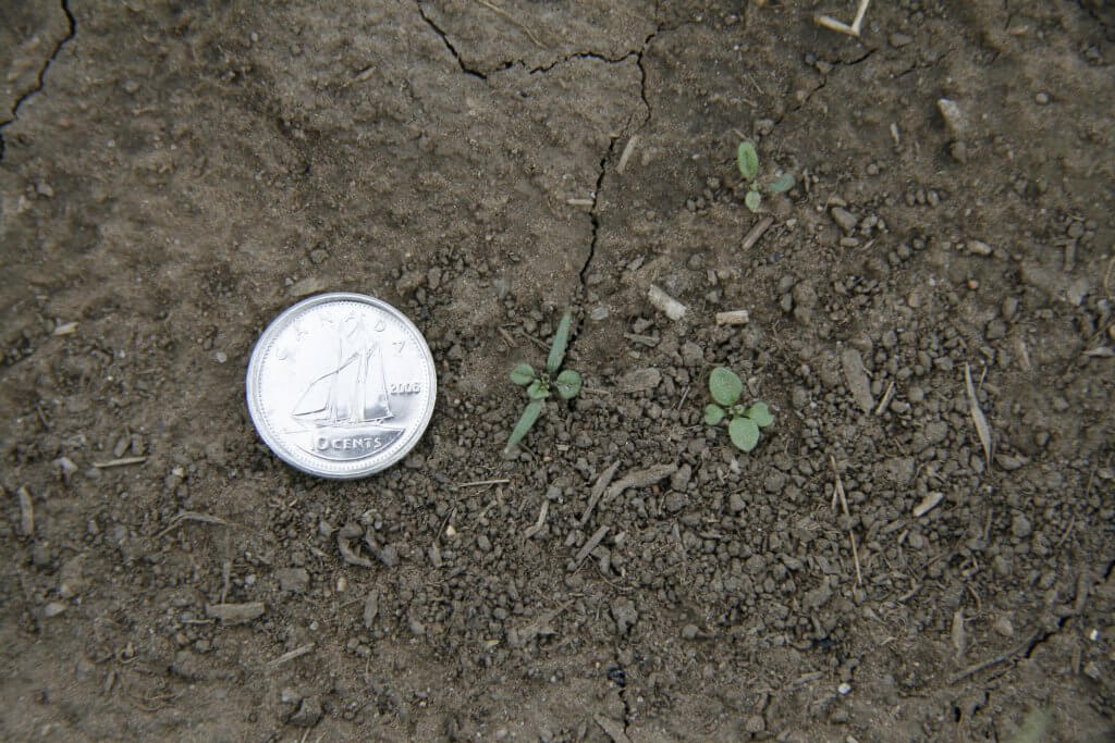
- Canopy: To start, we need to look at the canopy that our application will go into. If it’s an early season spray into a seedling crop, then the canopy won’t be much of a barrier. Lower water volumes can be possible. Droplet size will only depend on the target type and the pesticide mode of action.
If it’s a later application into the bottom of a maturing canopy, the foliage may intercept the spray before it reaches the target area. More water will likely be needed, and droplet size may become more critical for getting the spray to its destination. Dense canopies are a real challenge and lower-canopy deposition usually benefits from finer sprays because the small droplets can turn corners better.
2. Water Volume: Regardless of canopy, the range of application possibilities will depend on the water volume and spray quality combination. It’s math: assuming some constant amount of coverage on each leaf, more layers of foliage will require more water. Using less water volume will make it necessary to use finer sprays to keep droplet numbers constant. More water will allow coarser sprays. This decision has implications for drift, and by extension, affects the number of hours we can spray in a day. More drift tolerance means better application timing and overall productivity.
3. Target Type and Droplet Behaviour: Whatever spray we use, the target plant or insect needs to intercept, collect, and retain the spray droplet. This is where the fun begins. Target leaves may be vertical or horizontal, large or small. Their waxy surface may be easy-to-wet or difficult-to-wet. The general rules of thumb are that larger, more horizontal and easy-to-wet surfaces are better suited for coarser sprays – these are intercepted more efficiently and stick readily. That is a reason why most broadleaf weeds and crops are very compatible with low-drift sprays.
On the other hand, smaller, vertically oriented and difficult-to-wet plants require finer sprays for effective targetting. Larger drops tend to miss these targets or bounce off them. Most grassy, and some broadleaf weeds (especially at early growth stages) fall into this category.
4. Mode of Action: There are nearly 30 modes of action on the herbicide world, and another ten modes for insecticides and fifteen for fungicides. The effect of droplet size and water volume on their uptake and translocation varies, and it’s probably not correct to generalize too much. There is one notable product, glyphosate. For this product, research has consistently shown that large droplets and more concentrated mixtures provide better uptake. But we’ve also seen problems when this is over-done, causing localized toxicity and limiting translocation.
With many products, we’ve sometimes seen better performance with finer sprays due to improved coverage, yet at other times less performance due to rapid evaporation. On the whole, it’s probably still fair to say that contact modes of action require finer sprays and higher water volumes, even if there is the occasional exception. And systemic products can typically handle coarser sprays. We’ve always been surprised just how coarse we seem to be able to push the system before any loss of efficacy.
What does it all mean? In spraying, we need to accommodate a lot of diversity. The average application is broad-spectrum, targeting large and small broadleaf and grassy plants. Many sprays are tank mixes of several modes of action. It’s impossible to prescribe a specific spray for each situation. We need a little bit of everything. And the spray should not be drift-prone. It’s easy to see that we need to aim for the middle to accommodate everything.
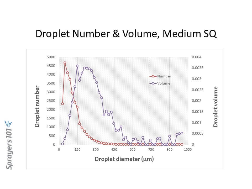
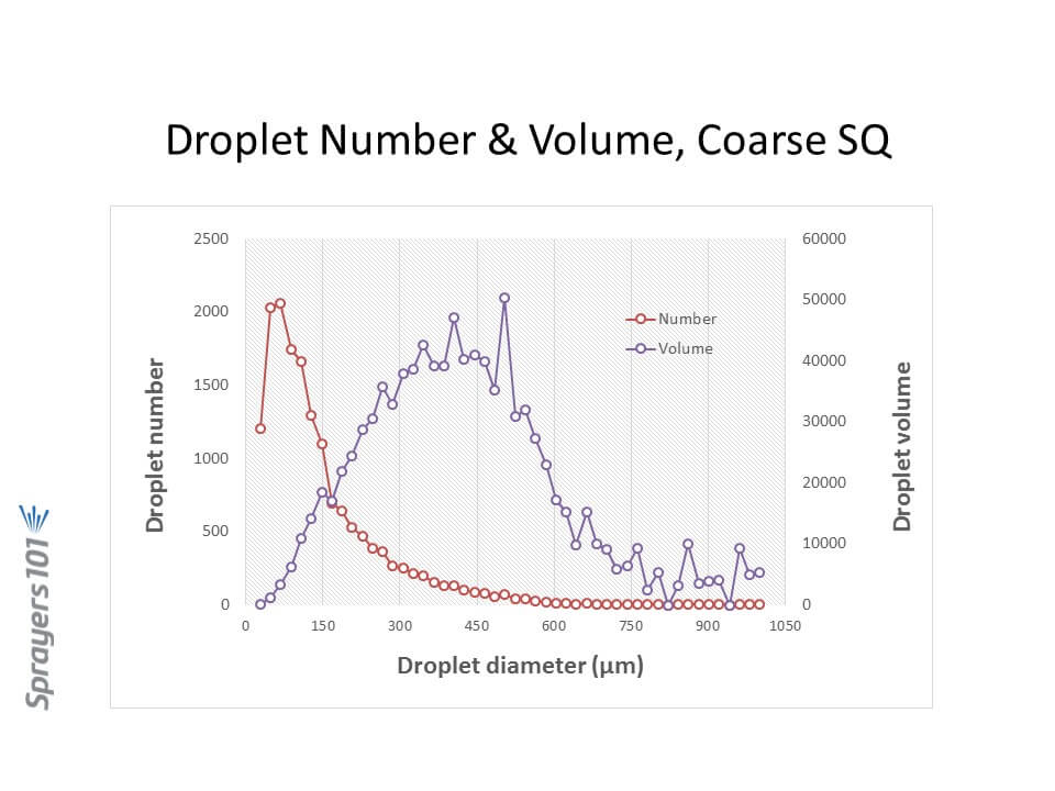
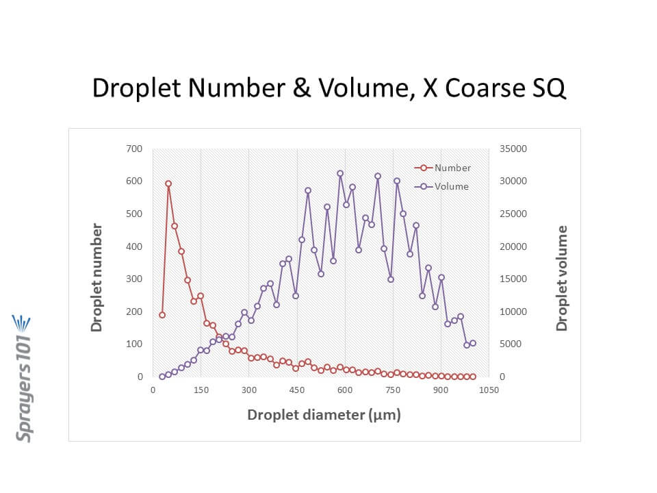
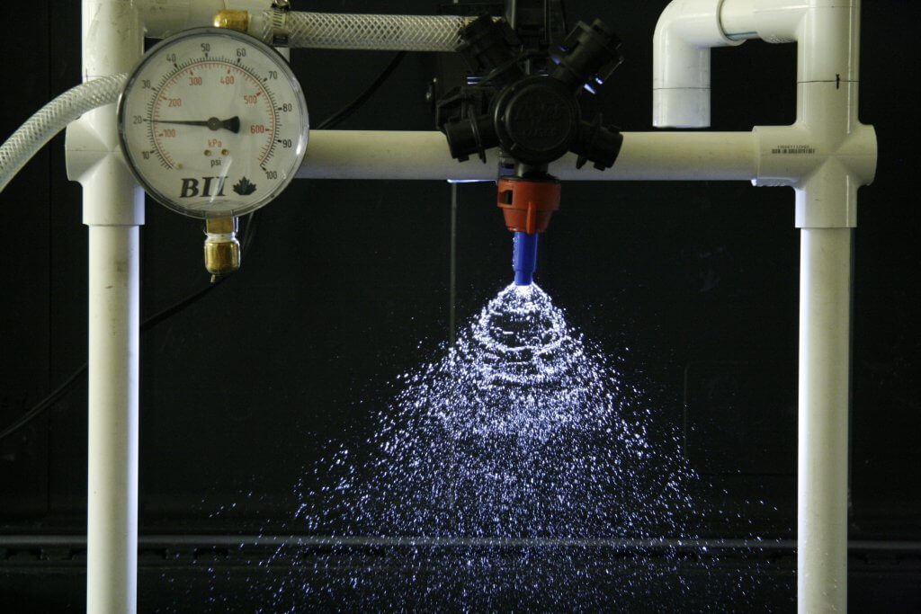
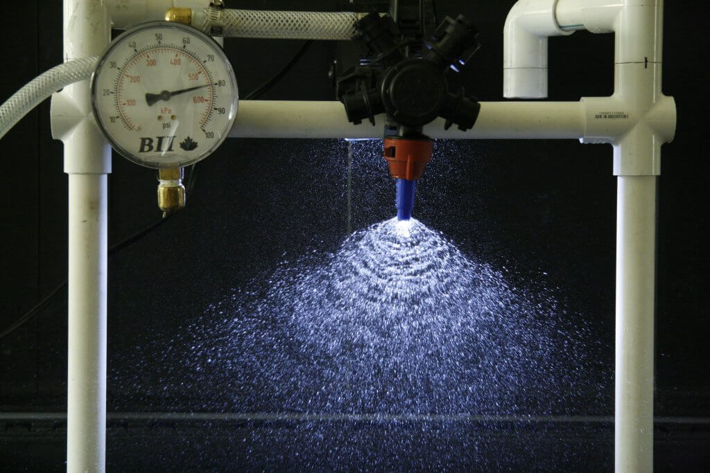
The traditional flat fan nozzle, either in its conventional or low-drift form, generates a wide range of droplet sizes that can range from 5 µm to about 2000 µm. If we need fine droplets, they’re there. If we need larger droplets, they’re also there. The proportion of the total spray volume in each specific size fraction depends on the nozzle choice and size, the spray pressure, and the adjuvant mix in the tank. Overall, the system is very robust, and although it requires some tweaking, a well chosen average spray can achieve most tasks well enough.
Our research has repeatedly shown that a Coarse spray is a good starting point that does most things well. It is acceptable to move into a Very Coarse or coarser category provided water volumes are also raised, and provided the target types and modes of action are suited for this change.
It is rarely necessary to spray finer than Coarse, and when this is done, we recommend against spraying finer than a Medium spray. There is simply no advantage from product performance, and drift risk becomes unacceptable.
Tweaking the System. In order to maximize the performance of your spray, and the efficiency of your overall spray program, here is some advice:
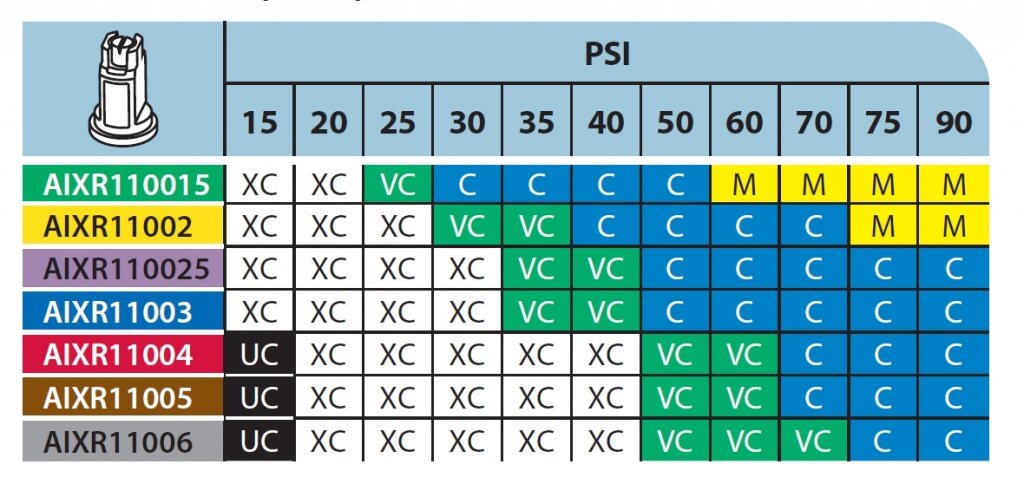
- Know the spray quality of your nozzles, and their response to spray pressure. Manufacturers publish this information in their catalogues and on-line. Make this your homework assignment.
- Use the coarsest spray that you can afford to. This will make the application safer, it will widen the weather window, and it will simply let you get more done in a day or a season. Coarse sprays work.
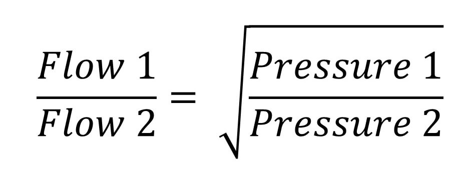
- Use spray pressure and water volume to fine tune the application for a specific purpose. If using a contact product, you can keep the same nozzle you used for a systemic product. Apply more water or use more spray pressure to generate more droplets.
- Do not skimp on water. Higher water volumes tend to make an application more uniform, robust, and crop-safe. Spray coverage improves. Canopy penetration improves. Coarser sprays are possible. The only exception to this rule is glyphosate, which works better in lower water volumes. But with higher glyphosate rates and more tank mixing, even that exception is disappearing.
- Learn as much as you can about how your pesticides work and where they need to be in your canopy. Apply your knowledge to select optimal water volumes and spray qualities.
- Be wary of people who advise very low water volumes in conjunction with fine sprays. They want to appeal to your need for efficiency, but do so at the cost of consistency and environmental stewardship. Plus these types of applications are illegal for many of our products.