Tag: nozzle

  • Broadcast Boom Nozzle Spacing

    Broadcast Boom Nozzle Spacing

    North American built boom sprayers have nozzle spacings of 20” (50 cm in the rest of the world), but other spacings such as 15” (37 cm) and 10” (25 cm) also exist. What are the reasons for these alternative spacings and do they offer any inherent advantages?

    Why spacing matters

    Nozzles are spaced along a boom to allow their fans (patterns) to overlap sufficiently at the target. In broadcast spraying, a uniform distribution of spray volume gives us the best chance for consistent coverage along the boom. Since flat fan nozzles produce a tapered pattern (i.e. the volume is highest in the centre and diminishes towards the edges), approximately 100% overlap (i.e. 50% from each neighbour) will produce a uniform swath.

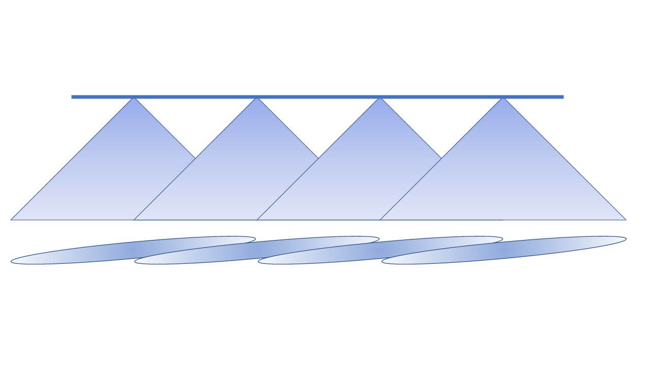
    Figure 1: Tapered flat fans that require some overlap are the default pattern type for agricultural boom nozzles. This is true of conventional and low-drift styles. Note that the flat fans are turned 15° to prevent the spray patterns from interfering with one another.

    The 100% overlap isn’t just for volumetric distribution. Flat fan spray patterns tend to have more and finer droplets in the centre and fewer and coarser droplets at the edges. All droplet sizes contribute to coverage in different ways, so the overlap ensures both number and sizes are evenly distributed along the entire boom.
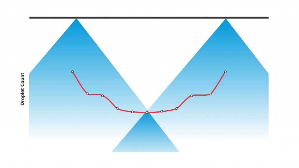
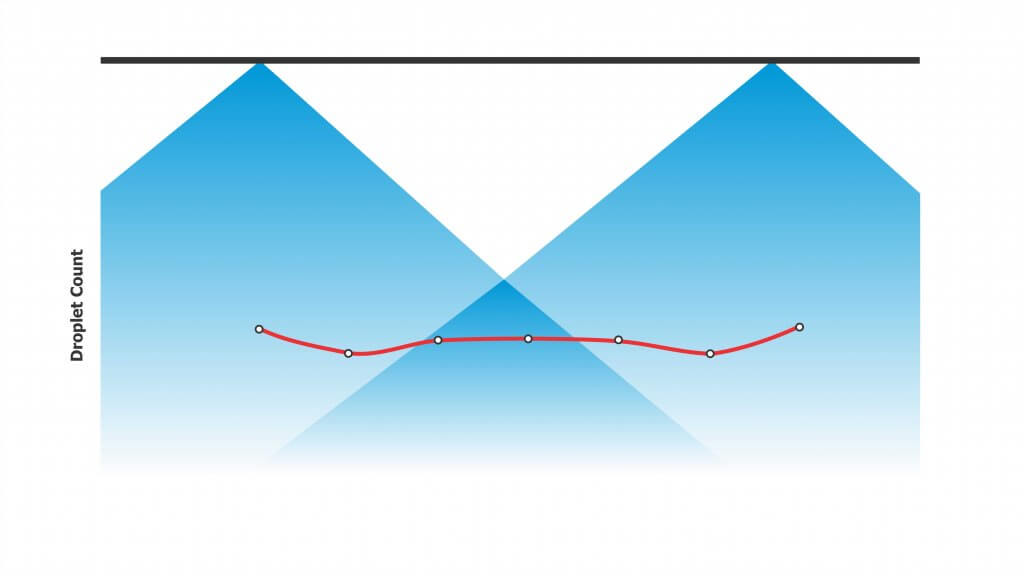
    Figure 2: 30% overlap may achieve volumetric uniformity. But because the centre of the pattern contains the majority of the smaller droplets, low overlap may result in low coverage in the overlap regions, resulting in striping.
    Figure 3: Consistent droplet number distribution along the boom requires at minimum 100% overlap (50% from each neighbouring nozzle). This blends those regions of the patterns with high and low droplet densities.

    The generic 20” spacing arose from long-held conventions about boom height, fan angle, and travel speed. Specifically, this spacing required a boom height of 20” to obtain good overlap of the once-dominant 80° fan angle. Combined with 0.15 to 0.3 US gallon per minute (gpm) nozzles and travel speeds of 6 to 8 mph, operators were able to apply 5 to 15 US gallons per acre (gpa) volumes. Using nozzles with smaller flow rates would generally result in nozzle blockages.

    But what if we want to change any of those variables? How does this affect nozzle spacing? Figuring out the pros and cons of an alternate spacing requires a little math and some contingency management.

    Boom Height Math

    First the math. If the boom has 20” nozzle spacing and we need 100% overlap, the width of the spray pattern at target height must be two times the nozzle spacing, which is 40″. You must calculate the required fan angle and boom height to achieve this. Most nozzle catalogues have tables to help with this, or you can download a handy spreadsheet to calculate your own scenarios here.

    For today’s standard 110° fans, a minimum boom height of 14” is needed to achieve 100% overlap. For 15” spacing, the height is reduced to 11”. For 10” spacing, we drop to a mere 7”. However, consider that most modern suspended booms are not operated at heights less than 24” to allow for sway. At that height, there’s plenty of overlap to go around for 20″ nozzle spacing. For those booms that are able to operate at a consistent height, narrower spacings permit lower heights that will reduce drift potential significantly. Every time we halve boom height, we also halve drift potential.
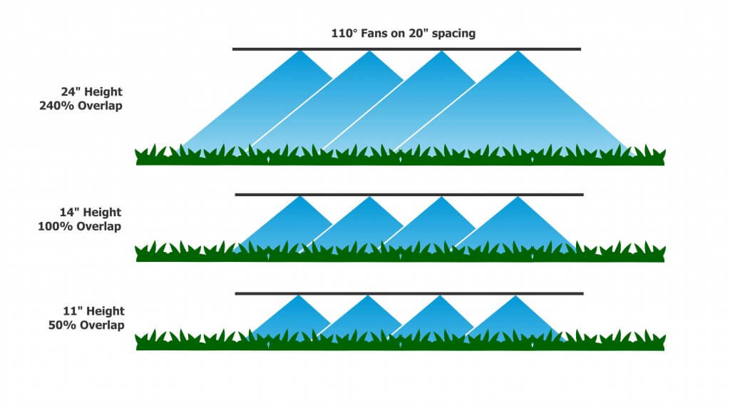
    Figure 4: Using 110° tips with 20″ spacing, the theoretical height at which we achieve 50% overlap is 11″ above target.

    By tilting the nozzles forward or backward from the vertical, we can reduce the boom height somewhat further and still get the same overlap. For example, for 20 and 15” spacings, angling nozzles forward or backwards by 30° allows us to drop the boom another 2” closer to the target.

    Contingencies

    A suspended boom hardly ever stays at a uniform height; It sways up and down with field conditions, topography, etc. This is why many operators set their booms above the minimum height – to prevent striping when the boom sways low. The penalty is that this increases the distance droplets need to travel, increasing drift potential and any turbulent displacement problems arising from the moving boom.

    Assuming a 110° flat fan at 24” boom height, each nozzle achieves a theoretical pattern width of about 70”, which is an overlap of 70÷20=3.4-fold or 240% on 20” nozzle spacing. Given a minimally-acceptable overlap of 50% (25% from each neighbouring nozzle), the boom could be as low as 11”. For 15” spacing, the minimum height for 50% overlap is 8”, and for 10” spacing it’s 5”. This means the narrower spray patterns gain 3” to 6” in allowed downward boom movement.
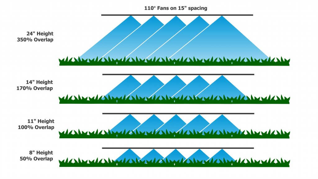
    Figure 5: Using 110° tips on 15″ spacing, the height for 50% overlap is 8″ above target.

    A second contingency is that spray patterns are rarely the exact value that the nozzle catalogues specify. A so-called 110° nozzle may operate at only 90°, or up to 150°, depending on the nozzle model, the spray pressure, and the tank mix. Learn more here and here. Patterns also don’t continue to grow at their rated fan angle, as droplets slow due to air-resistance and fall more vertically due to gravity. For that reason, a visual check is recommended to ensure the expected overlap is achieved.
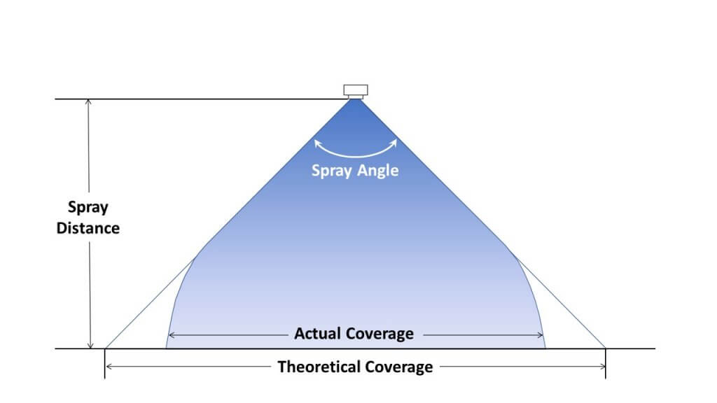
    Figure 6: Fan angles indicate initial trajectories of droplets at the edge. With distance, gravity pulls these droplets downward, narrowing the pattern width from that achieved theoretically (figure adapted from image in TeeJet catalogue).

    A third issue to consider is less related to boom height but nonetheless affects spray distribution. Small droplets move with air currents, and the turbulence created by large, fast sprayers creates enough turbulence to move these droplets significantly. A perfect pattern under static conditions can look quite different at a fast travel speed with a modest side wind. Low booms may help prevent some of this displacement because droplets spend less time in flight, and their average velocity is faster.
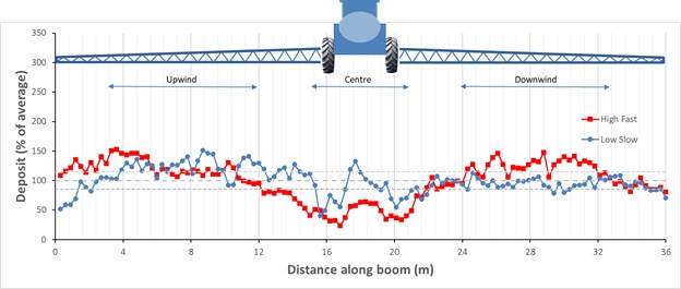
    Figure 7: Spray deposition onto a 2 mm string to measure deposit uniformity for a fast travel speed and high boom and a slow speed, low boom configuration.

    Flow Rate Math

    Flow rate requirements per nozzle change whenever we equip a boom at an alternate spacing. The basic formulae are shown below.
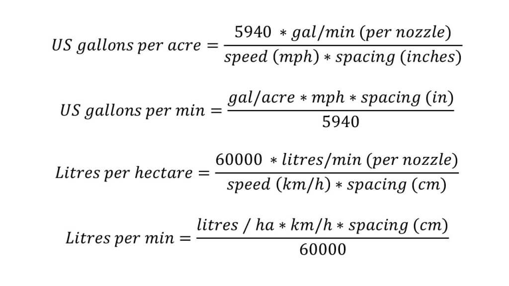
    Moving from a 20″ to a 15″ spacing would require a nozzle with 0.75 of the flow rate, approximately from a 02 to 015 size, or 03 to a 025 size, or 04 to 03 size, etc.

    Pulse Width Modulation

    The use of Pulse Width Modulation (PWM) has increased the overlap requirement. With PWM, alternate nozzles are on a 180° timing offset from their neighbours. This means that when running >50% duty cycle, when one nozzle is temporarily off, its neighbours are on. These neighbours’ patterns must now span the gap, and 100% overlap is the absolute minimum to achieve this. PWM users therefore select the wider pattern angles and some opt for >100% overlap.
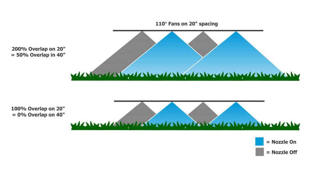
    Figure 8: Pulse Width Modulated booms require 200% overlap so that the entire boom receives proper coverage when the alternate set of nozzles is off. For 110° fans at 20″ spacing, the minimum boom height would be 21″

    PWM Considerations

    • High flows (greater than 1 US gpm at the nozzle) that are common for fertilizer top-dressing may require higher-flow PWM valves.
    • Narrow spacings reduce the individual nozzle flow rates and can therefore support higher application rates before triggering a larger valve requirement.
    • PWM valves aren’t cheap and for example 15″ spacing compared to 20″ spacing adds 24 valves on a 120′ boom.

    Banding

    We noted that 20” nozzle spacing is a standard because it corresponds to what has traditionally been achievable with available boom heights and spray pattern angles. But things can change.

    Narrower spacings such as 15” originate with row crops and planter row spacings of 15” or 30”. These spacings exist so the spray pattern can be placed either over the top of a crop row, or in between the rows for banding. Using narrower fan angles and/or lower boom heights, together with “even” (as opposed to “tapered”) fans, banding sprays can be applied over the top of, or between crop rows. Or drop hoses can reach between the rows for top-dressing or directed sprays into the canopy.

    Canopy Penetration

    With narrower spacing, it can be argued that a greater proportion of the boom length has spray directed directly downward (corresponding to the centre of the pattern). Whether or not this translates into better penetration of a canopy is a fair question. In laboratory trials, use of 10” or 20” spacing did not improve penetration into a broadleaf canopy. But if the lower boom height afforded by the narrower spacing was utilized, some improvements in the deposit of angled sprays onto vertical targets was observed.

    Adjusting to Narrower Spacings

    As we showed earlier, use of 15” or 10” spacing booms for broadcast sprays requires a smaller nozzle size to achieve the same spray volumes as the 20” spacing. If boom height remains constant, narrower spacings result in greater pattern overlap which provides more latitude for sway. Alternately, lower boom heights can be used.

    Using smaller nozzles on narrower spacing presents some challenges. Generally, smaller nozzle size means finer spray quality. If an operator wants to retain the spray quality they had on a 20″ spacing, they may opt to use lower pressure (not advisable for non-PWM systems) or swap to different nozzle design that can produce the desired spray quality at the lower flow rate.

    Smaller nozzles are more prone to plugging, so that needs to be managed with filtration, filling practices and water sourcing. Be aware of the the product formulations and their requirements for filter mesh size. Most dry products specify a 50 mesh filter (or coarser). Also, check size options for nozzles. The smallest size for most nozzle models is 015, but certain PWM-specific nozzles are only available in 03 or larger.

    The marriage of narrow spacings with individual nozzle shutoff can result in a versatile system capable of producing high resolution banded sprays in narrow seeded crops. For example, consider a boom with a 10” nozzle spacing spacing that matches the seeder row spacing. The operator can shift from 10” to 20” or 30” from the cab if the valve control software allows it. With accurate guidance and good boom levelling, topdressing foliar products (e.g. nutrients, fungicides) can follow the crop row precisely.

    Spot Sprays

    Spot sprays present a situation where compromises are needed. Some, such as WEEDit, utilize narrower nozzle spacings to allow better treatment resolution and increase product savings. Any one nozzle or sets of adjacent nozzles may be triggered by the sensor. For single nozzle activation, to preserve the value of the better resolution a uniform, narrow band of spray needs to be created. This means a 30° or 40° fan angle from a banding nozzle will be necessary. For example, a 24” boom height will result in a 13” band with a 30° fan, and an 18” band with a 40° fan. In the latter case, the dose would be diluted by 80%, wasting much of the potential savings.
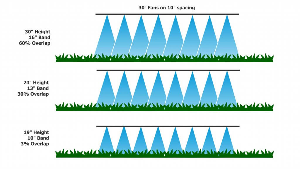
    Figure 10: Boom height is critical for banded sprays and for spot sprays. Too wide a pattern on a single nozzle reduces dose, too narrow creates misses.

    Frequently, a patch of weeds will trigger several adjacent nozzles. Now these individual bands need to work together to create a uniform swath. This will inevitably require some overlap to avoid gaps, but too much overlap will result in bands where twice the dose will be applied. A tapered fan may suit this situation better. As a result of these varying needs, tolerances for spot spray boom height are even more strict than for broadcast spraying. More thoughts on spot spray nozzle selection are here.

    Conclusions

    Narrower nozzle spacings on a broadcast boom allow somewhat lower boom heights and these can in turn reduce drift and improve deposition of sprays. Lower flow nozzles will be needed with narrower spacings, requiring management of plugging and potentially a more drift-prone spray quality. The value of narrower spacings depends on the availability of booms that control sway, allowing them to operate at uniform, low heights.
  • Spraying Ginseng with Arag Microjets

    Spraying Ginseng with Arag Microjets

    In June 2013 we ran a ginseng spraying workshop and we learned as much as the growers did. Ginseng is notoriously difficult to spray:

    • It is highly susceptible to pathogens given the high humidity and still conditions generally found under the shade structure.
    • It forms a solid ceiling of leaves that resist spray penetrating to the stem and crown below and makes under-leaf coverage very difficult to achieve.

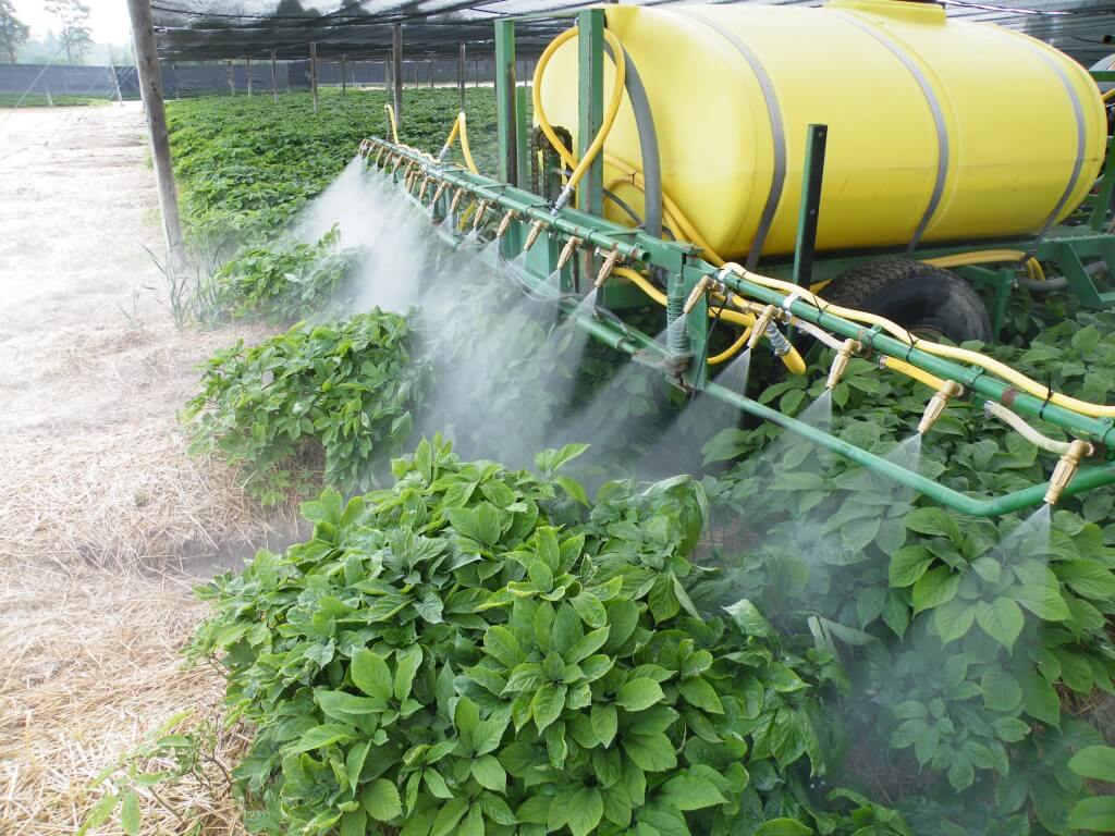
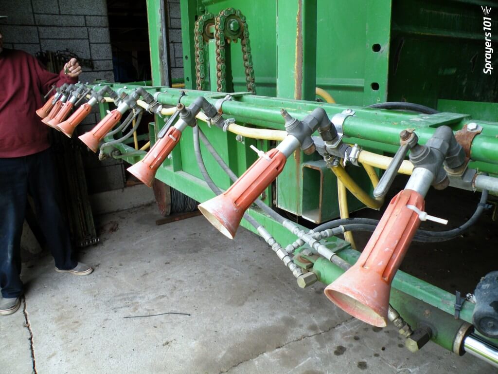
    Many growers have (wisely) walked away from the old Casotti sprayers, which have been shown to give erratic coverage at best. They have adopted the Arag Microjet system with it’s characteristic orange shields. The >$80.00 CAD price tag for each nozzle is due to the brass mixing valve and swivel joint, as well as import costs from Italy. Contrary to popular belief, it does not use air-assist, or air-induction – it is strictly hydraulic. It does tend to create a ‘wake’ of air movement at high pressure. This phenomenon is called air entrainment and it is caused by large droplets travelling at high speed.

    Classic Arag microjet nozzles.
    Classic Arag microjet nozzles.

    This nozzle is essentially the business-end of a spray gun. The way it is used in ginseng it works more-or-less like a hollow cone disc-core assembly. This begs the question “Why not use the cheaper and more readily available ceramic disc-core?” We set out to compare the two options using water sensitive paper set within the canopy. These yellow, paper targets turn blue when sprayed, clearly showing spray coverage.

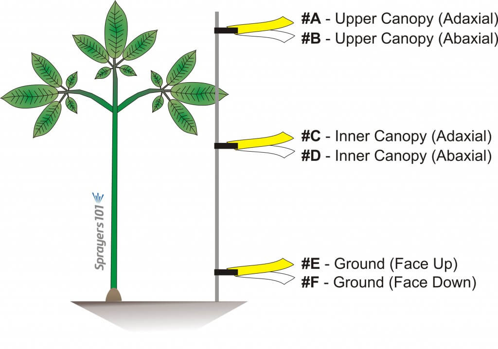
    Location of water-sensitive papers in the ginseng canopy.
    Location of water sensitive papers in the ginseng canopy.

    Determining rates

    The first step was to determine the output rate for each nozzle. Generally, nozzle manufacturers provide rate tables showing how much volume a nozzle emits by time (e.g. US gallons per minute) at a given pressure. Finding these tables for the 1.5 millimetre Arag Microjet proved difficult. When we finally found one, it was discovered the rates were established for 200 to 850 pounds per square inch. This is excessively high pressure for a typical boom sprayer, so tables had to be developed for lower pressures.

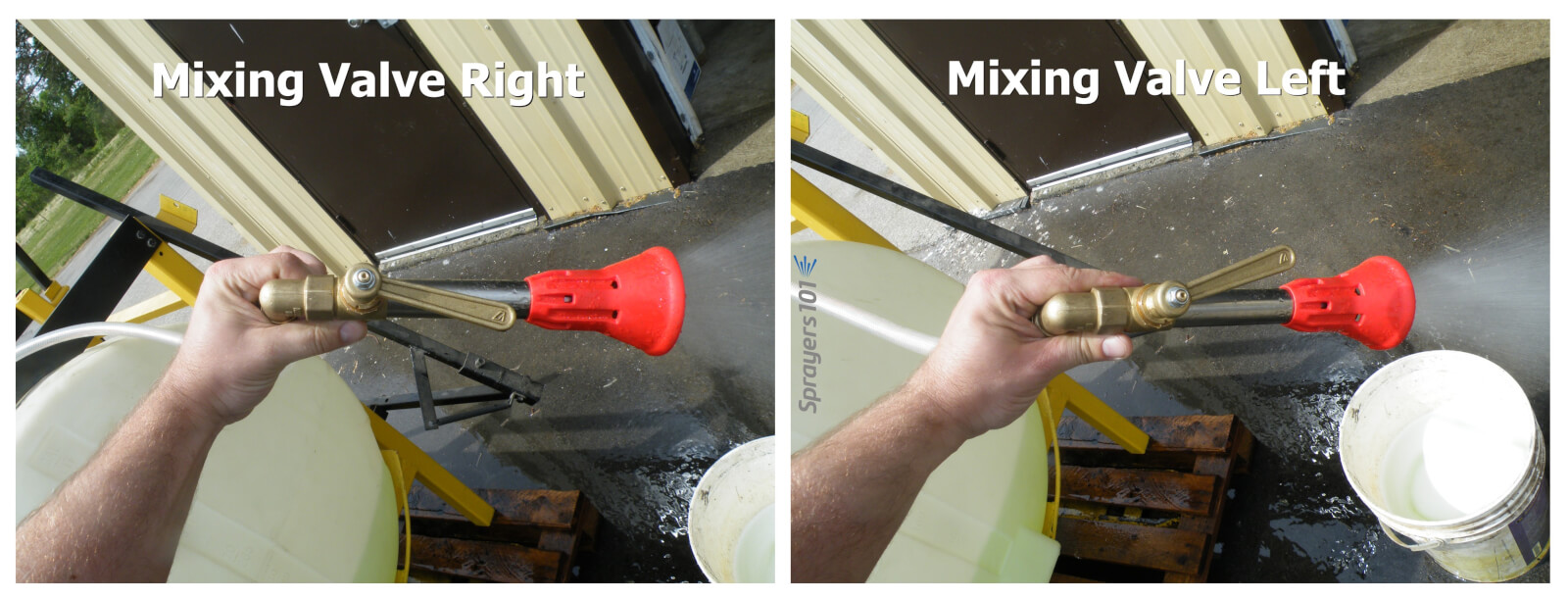
    Classic Arag microjets have a mixing valve that opens the spray up into a hollow cone, or collapses it into a tight stream. This also changes the rate. It can never be shut off completely, and it's hard to adjust consistently.
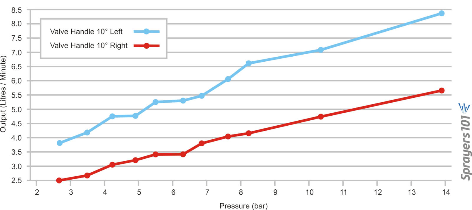
    Classic Arag microjets have a mixing valve that opens the spray up into a hollow cone (valve handle left or right), or collapses it into a tight stream (valve handle middle). The valve position also changes the rate. It can never be shut off completely, and it’s hard to adjust consistently.
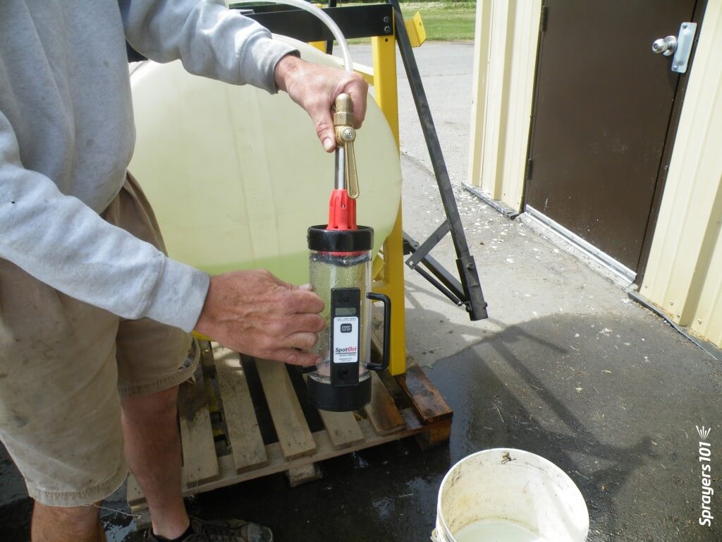
    Determining nozzle rate using the Innoquest Spot-On SC-4.
    Determining nozzle rate using the Innoquest Spot-On SC-4.

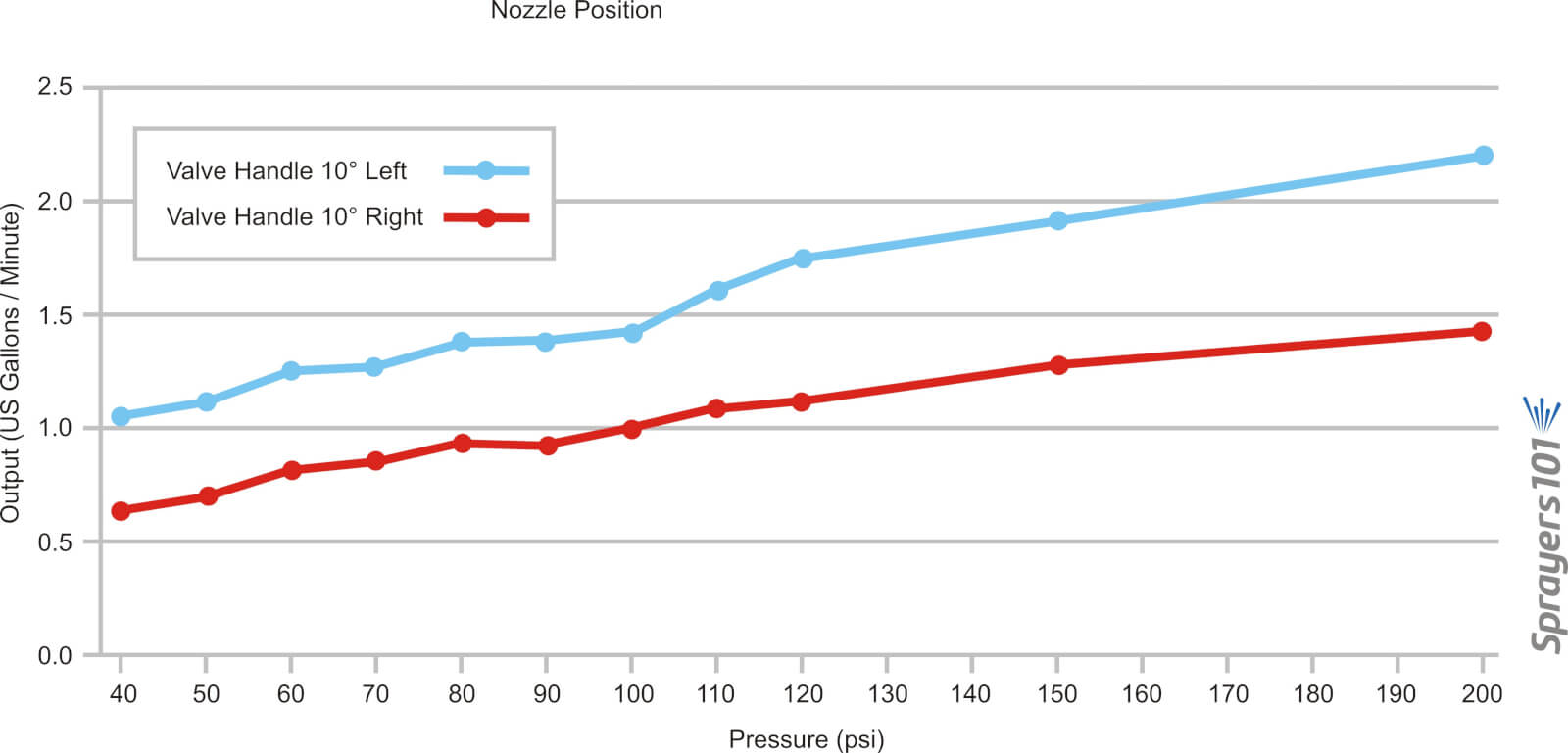
    Further, given the odd design of the mixing valve, it was determined that moving the handle ~10 degrees left of centre, or ~10 degrees right of centre, gave a difference of as much as 60%. The table below  shows the outputs for a 1.5 millimetre nozzle with the handle in both positions and the two graphs show the results… well… graphically. Outputs were determined using the Innoquest Spot-On SC-4, but the frothing effect created by the nozzles may have created minor errors. Each rate is the average of a minimum of three samples.

    Valve SettingPressure (psi)Avg Output (gpm)Pressure (bar)Avg Output (L/min)
    10 degrees left401.022.763.86
    10 degrees left501.13.454.16
    10 degrees left601.254.144.73
    10 degrees left701.254.834.73
    10 degrees left801.385.525.22
    10 degrees left901.46.215.3
    10 degrees left1001.456.895.49
    10 degrees left1101.67.586.06
    10 degrees left1201.758.276.62
    10 degrees left1501.8710.347.08
    10 degrees left2002.213.798.33
    10 degrees right400.652.762.46
    10 degrees right500.73.452.65
    10 degrees right600.84.143.03
    10 degrees right700.854.833.22
    10 degrees right800.95.523.41
    10 degrees right900.96.213.41
    10 degrees right10016.893.79
    10 degrees right1101.077.584.05
    10 degrees right1201.18.274.16
    10 degrees right1501.2510.344.73
    10 degrees right2001.3713.795.19
    Average 1.5 mm ARAG Microjet output at a range of pressures and two valve settings in US Imperial units.
    Average 1.5 mm ARAG Microjet output at a range of pressures and two valve settings in US Imperial units.
    Average 1.5 mm ARAG Microjet output at a range of pressures and two valve settings in Metric units.
    Average 1.5 mm ARAG Microjet output at a range of pressures and two valve settings in Metric units.

    Comparing nozzles

    Using the grower’s typical ground speed of 5 km/h (~3 mph) and operating pressure of 6.9 bar (100 psi), we found four TeeJet disc-core combinations that emitted a hollow cone pattern and approximately the same output as the Arag Microjets. The five nozzles sets tested were:

    1. ARAG Microjet® 1.5 mm = ~0.95 US g/min avg at 100 psi
    2. TeeJet® D8-DC25= 0.97 US g/min at 100 psi= ~97° cone
    3. TeeJet®D7-DC45= 0.97 US g/min at 100 psi= ~81° cone
    4. TeeJet®D4-DC46= 0.88 US g/min at 100 psi= ~33° cone
    5. TeeJet®D6-DC45= 0.93 US g/min at 100 psi= ~81° cone

    We did not use nozzle drop hoses (aka drop arms or hose drops) because it has already been firmly established that they are absolutely required to achieve under leaf coverage See OMAFRA factsheet 10-079 and this article.

    Observations

    While there were some complications with setting up the papers for the demo, we observed the following:

    1. The output of each Microjet nozzle can be as much as 50% more or less than expected without being visually detectable and output for each nozzle must be confirmed before spraying. Therefore, outputs should be confirmed before every application.
    2. Microjets at 100 psi emitting ~890 L/ha (~95 US gallons per acre) gave satisfactory coverage on all upward facing targets, but unsatisfactory under-leaf coverage. This has been demonstrated many times before.
    3. The TeeJet D7-DC45 combination emitting a similar rate gave satisfactory coverage on all upward facing targets, but unsatisfactory under-leaf coverage. They may be a viable alternative to the Microjets.
    4. Nozzle drops are advised to achieve under-leaf coverage.

    The demo also raised some questions:

    1. Did the TeeJet disc-core push the canopy apart as much as the Microjet? The audience noticed there was some leaf-shadowing where the cards did not get complete coverage using disc-core. This might have been coincidence, or it may not have. This question will be addressed in a research trial next season, but for now, the D7-DC45 appeared to give similar coverage to the Microjet.
    2. Can nozzle drops be avoided if pressure is raised to 27.5 bar (400 psi)? Thanks to one grower trying this experiment in his garden after the demo, we saw some under-leaf coverage is possible at such high pressures, but this occurred at the cost of a lot of noise, diesel fuel and considerable wear on the ceramic Microjet discs. The grower tested these tips and discovered they needed replacement after only two years of use. Nozzle drops are cheaper, easier and result in considerably more spray in the under leaf positions.
    3. We saw what minimal and excessive foliar coverage looked like, and determined how much variability there was from one nozzle to another. A significant question was “How much spray can be saved when using a more accurate application?” and the answer is yet to be determined, but could be well in excess of 10% of the typical spray volume. Given that this crop can be sprayed more than 100 times over it’s 3 or four years before harvest, this represents significant savings in pesticides and refill time.

    Additional – Newer ARAG Microjet Design

    Since this work was performed, growers have been exploring a newer option from ARAG.

    They are an improvement over the older version insofar as they are more easily calibrated and held at a given rate thanks to a lock nut. They still employ a 1.5 mm diameter ceramic disc, but this can be changed for a 1.0 or 1.2 quite easily. They are still somewhat finicky when trying to set a consistent spray quality and rate from nozzle to nozzle, but are better than the mixing-valve option.

    Learn more in this article.

    Custom-made ginseng sprayer. A standard design.
    Custom-made ginseng sprayer. A standard design with newer, cheaper and easier-to-use ARAG microjets.

    Special thanks to Syngenta Canada for providing lunch, to C&R Atkinson Farms Ltd. for hosting, to TeeJet for supplying the disc-cores and water-sensitive papers, and to Dr. Sean Westerveld, Dr. Melanie Filotas and OMAFRA summer student Megan Leedham for contributing to the workshop.

  • Larry the Low-Drift Nozzle – Parody

    Larry the Low-Drift Nozzle – Parody

    Bridgette Readel (@BMReadel) is back! This time singing that holiday classic “Larry the Low-Drift Nozzle”! Read the lyrics and then head to the bottom of the article to enjoy Bridgette’s rendition.

    You know Flat Fan and Flood Jet and Pulse Width and Wilger,
    Hypro and Greenleaf and TeeJet and Lechler.
    But do you recall
    The most famous nozzle of all?

    Larry the low-drift nozzle
    Had a very “big-drop” spray
    And if you ever saw it
    You’d never see it drift away.

    All of the other nozzles
    Used to laugh and call him names
    They never let poor Larry
    Join them on their spray boom frames.

    Then one windy summer’s eve
    Farmer came to say
    “Larry with your spray so coarse
    Won’t you fight this gusty force?”

    Then how the neighbours loved him
    As they shouted out with glee
    “Larry the low-drift nozzle
    Stewardship for chemistry!”

  • Airblast Nozzles – On or Off?

    Airblast Nozzles – On or Off?

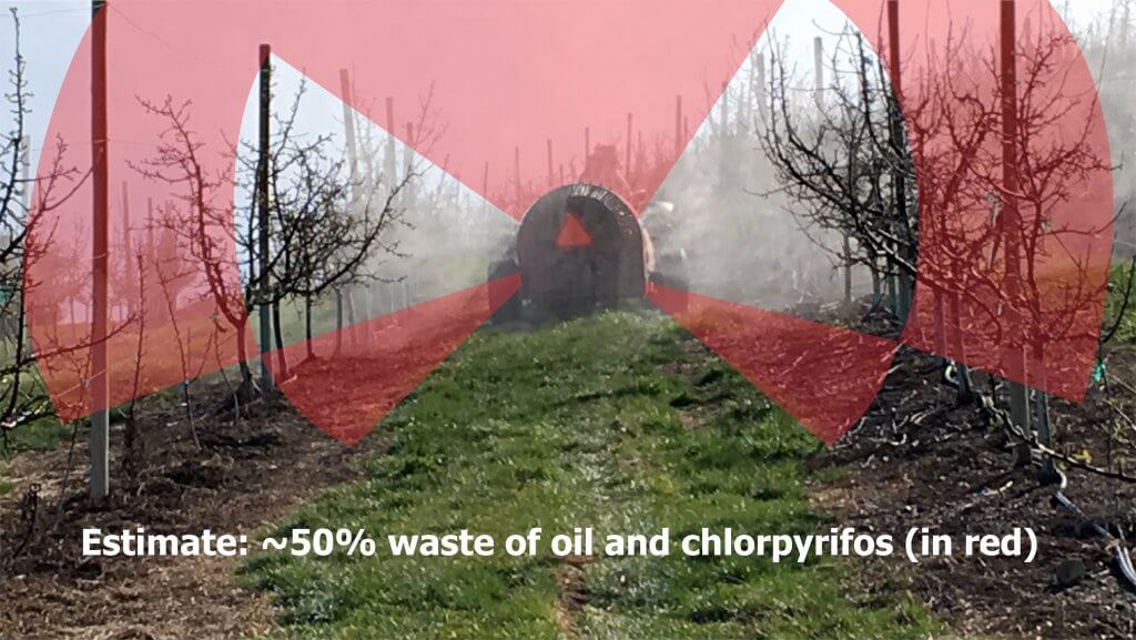
    Spray that is not directed at the target is wasted spray. Many pesticide labels specifically require the operator to restrict spray to the target canopy. Spray that escapes above the canopy is a significant source of off-target drift. Foliar applications that extend below the canopy are not efficacious and represent waste and lost productivity.

    A spring application or oil and chloropyfiros. Estimate of 50% waste (in red).

    Air carries spray droplets, so the first step in any adjustment should be to perform a ribbon test to ensure the air outlets are oriented correctly. This is achieved by adjusting deflectors (e.g. low profile axial), the air outlets on a tower, or the entire head on a wrap-around design with individual fan/nozzle combinations.

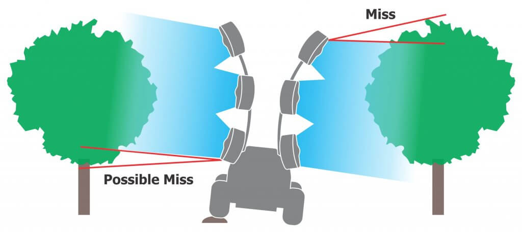
    Spray height should always exceed the canopy height by a small degree. This compensates for the increase in wind speed with elevation, the potential loss of spray height with faster travel speeds, and uneven alleys that cause the sprayer to rock, which changes the spray angle.

    Spray angles change as a sprayer rocks on uneven alleys. It is more important that spray is directed at the top of a canopy than at the bottom.

    It is less critical that spray align with the lower portion of the canopy. As air energy wanes, or as droplets begin to lose momentum, finer droplets will slowly fall, depositing on random surfaces. Coarser droplets will quickly fall towards the bottom of the canopy, settling primarily on upward-facing surfaces. This secondary deposition can also occur from the cumulative impact of blow-through from upwind rows.

    Once the air is aligned, park the sprayer in an alley. Stand behind the sprayer and extrapolate a direct line from each nozzle to target canopy. Nozzles that point at the canopy should be left on. Nozzles that point above or below can be blocked, or turned off via valves or rotating roll-overs. Some roll-over nozzle bodies can be swiveled up or down 15 degrees to fine tune the spray angle. An alternative would be to permanently rotate the nozzle body fitting in the boom line. When aiming nozzles using a roll-over nozzle body, be careful not to swivel them too far or the valve will partially close and compromise the spray pattern.

    Use a ladder when adjusting nozzles on a tower sprayer. Some sprayer chassis and tanks are designed to accept a climber, but even so they can be slippery. Please be careful.

    When extrapolating, remember that the centre of a nozzle only indicates the centre of the spray pattern. Cone and fan angles can span 60 to 110 degrees, depending on the influence of air. Therefore, even though the centre of the lower-most nozzle intersects the bottom of the target canopy, you may still be able to turn it off because the nozzle above has that portion covered.

    Adjust spray distribution across the boom at the beginning and roughly mid-way through the spray season to ensure the sprayer will uniformly cover the target with the optimal volume. These adjustments should account for both canopy growth and fruit set.

    For example, as the season progresses in an orchard, fruit may cause limbs to hang lower and warrant a new spray distribution. Turning on the bottom nozzle position will help, but it doesn’t account any increase in density throughout the canopy. You may need more volume distributed across the entire boom. Another example: as grape bunches begin to close, sprayer operators may direct fungicides exclusively at the fruit zone and not the entire canopy.

    Remember to always check coverage using water sensitive paper. It’s not worth saving a bit of spray if you’re missing a bit of your target.

  • The Droplet Size Debate

    The Droplet Size Debate

    Funny how some issues never go away. For as long as I’ve been in the sprayer business, the question of ideal droplet size for pesticide application has remained a hot topic.  At its root are the basic facts that small droplets provide better coverage, making better use of water, but large droplets drift less.  So why are we still debating this? Because we need both of these properties to be efficient, effective, and environmentally responsible. Ultimately, the droplet size question is reduced into one of values, where everyone’s individual priorities play a role. 

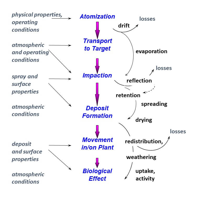
    First, let’s talk about basic principles. To be effective, an active ingredient must make its way from the nozzle to the site of action in the target organism. On the way, it encounters several obstacles as summarized by Brian Young in 1986.

    Figure 1: The dose transfer process of pesticides (after Young, 1986)

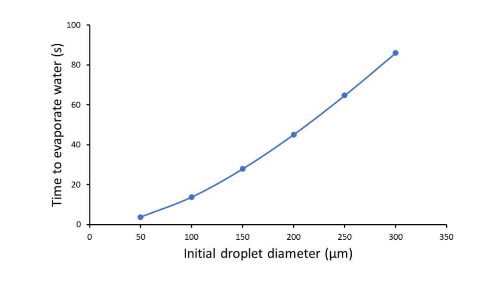
    After atomization and before impaction, the spray encounters two main losses, evaporation and drift. Both of these are more severe for smaller droplets. Smaller droplets have a greater ratio of surface area to volume for any given spray volume, and can evaporate to a much smaller size, even to dryness depending on the formulation, in seconds. For water-soluble formulations, one consequence is lower uptake. Oily formulations may maintain efficacy, but neither type can escape the second effect, spray drift.

    Figure 2: Time to evaporate all water from droplets of various sizes, based on the “two-fluid” model developed by Wanner (1980). Based on 0.8% v/v non-volatile, non-soluble addition, 20 ºC, and 50% RH. This model suggests that final droplet diameter is 20% of initial diameter. Reproduced from Microclimate and Spray Dispersion by Bache and Johnstone (1992, Ellis Horwood Ltd).

    Small droplets are more susceptible to displacement by wind currents due to their small mass. There is no magical size above which drift is no longer possible, but we’ve generally used diameters of 100, 150, or 200 µm as a theoretical cutoff. The proportion of the spray’s volume in droplets smaller than these diameters can be called “drift potential”, and this value is useful to measure the impact of nozzle type, pressure, or formulation on that phenomenon.

    But it’s not quite that simple. Even a small droplet may resist drift if its exposure to wind is limited, perhaps through a protective shield shroud, or lower boom height. Or by increasing its speed through air assist. Higher energy droplets resist displacement.

    These mitigating strategies aren’t lost on sprayer manufacturers who have used them for decades to build lower drift sprayers.

    The next phase of the dose transfer process is interception. The droplet has to encounter its target, but the process is mostly coincidence. Simply put, the target has to be in the way of the droplet’s flight path for the two to meet. Denser canopies are therefore more effectively targeted. A larger number of droplets (smaller droplets or more carrier) also improve the odds. But it’s not that simple. Flight paths can change. That’s where small droplets are more inventive. Because they respond to small air currents, and because such small currents surround most objects, the smaller droplets can weave around objects, following the small eddies generated by air flows. As a result, we’re more likely to find smaller droplets further down in denser, more complex canopies where the eye can’t follow. They simply cascade through.

    Larger droplets, on the other hand, resist displacement by air and travel in straighter lines. They tend to hit the objects they encounter. For that reason, larger droplets are intercepted by the first object they reach and only make their way deeper into a canopy if the path is clear. In other words, vertical, sparser objects allow larger droplets to pass by.

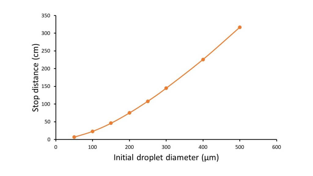
    These properties are related to the droplet’s inertia, and are best described by a parameter known as “stop distance”. Assuming an initial velocity, stop distance is the distance required by a droplet to slow to its terminal velocity.

    Figure 3: Stop distance as a function of droplet size. Assuming a 20 m/s initial velocity (similar to exit velocity of a hydraulic nozzle) and gravity assistance. Note that smaller droplets without the benefit of air assist lose their initial velocity within a few cm of the nozzle exit. Reproduced from Microclimate and Spray Dispersion by Bache and Johnstone (1992, Ellis Horwood Ltd).

    These characteristics, combined with the aerodynamic properties of objects such as tiny insects, cotyledons, leaves, stems, etc. govern the collection efficiency of sprays. Small, slow moving droplets are thus best captured by small objects that don’t create strong enough deflections of airflow to steer the droplets past. Large objects that redirect air around them very effectively are better collectors of the larger or faster droplets whose kinetic energy can guide them through this turbulence. It’s also a matter of probability, as the smaller objects tend to have a lower likelihood of encountering the relatively scarce large droplets of any given spray.

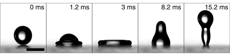
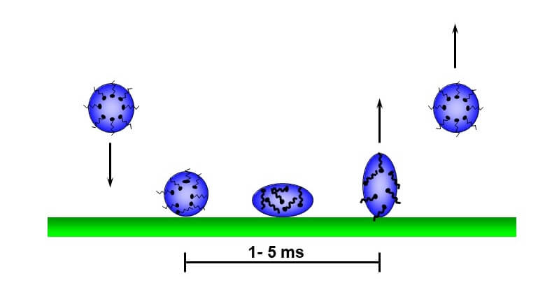
    But once again, that’s not the end of the story. Interception is followed by a critical stage, retention. Objects must be able to hold onto the droplets they intercept. Slow motion video has shown that droplets flatten out on contact with an object as the liquid converts impaction velocity into lateral spread. Once at full extension, the flattened droplets will collapse even beyond their original round shape, pushing them away from the surface and possibly causing rebound. A rebounding droplet may eventually land on target, but that would be a matter of fortune. It’s better if the leaf can offer enough adhesion, diminishing the power of the rebound oscillation, allowing droplet to stick the first time.

    Figure 4: Droplet deformation during impact (C. Hao, et al. 2015. Superhydrophobic-like tunable droplet bouncing on slippery liquid interfaces. Nature Communications. August 2015).

    Small droplets have less mass, and tend to be retained more easily. But more than size is at play here. The morphology and chemistry of the leaf surface is also important, with crystalline or more oily surfaces offering less adhesion for droplets. The physico-chemical properties of the spray mixture becomes important, as characteristics such as dynamic surface tension and visco-elasticity affect spray retention. These properties are optimized through the product formulation effort, and possibly via adjuvants added to the tank.

    We sometimes classify targets as “easy to wet” or “difficult to wet” to summarize these properties. Most grassy plants (foxtails, cereals) are difficult to wet (there are exceptions, such as the sedges) and broadleaf plants vary from the easy to wet pigweeds to the difficult to wet lambsquarters and brassicas. Easy to wet species can retain larger droplets than difficult to wet species, and that’s one reason why finer sprays are preferred for grassy weed control (leaf orientation and size are another).

    Figure 5: Droplet deformation, and surfactant molecule alignment, during impaction. The inability of surfactants to reach optimal alignment quickly, and for the target surface to absorb these forces, leads to rebound.

    A few words about surface tension. Although surfactants reduce surface tension and facilitate spreading, this may not be enough to improve spray retention. To be effective, surfactant molecules need to align themselves with the surface of the droplet so they can be a “bridge” at the interface where the droplet meets the target surface. This takes time. The oscillations that occur during impaction continuously create new surfaces, and if surfactant molecules don’t follow suit immediately, the droplet will behave as if no surfactant is present.  Specialists measure “dynamic” surface tension, i.e., the surface tension at young surface ages – a few milliseconds – to better predict spray retention. Very young surface ages have surface tensions of plain water, even with a surfactant present. Only certain surfactants, or higher concentrations of surfactants, can actually improve spray retention.

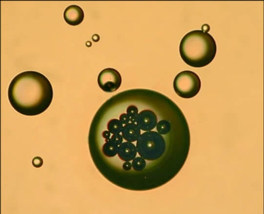
    When air-induced nozzles were introduced in the mid 1990s, one of their claims was the improved spray retention due to air inclusions (bubbles) in the individual droplets. These bubbles made the droplets lighter, and also reduced their internal integrity, promoting breakup on impaction. As a result, the coarser sprays they produced actually had some of the same efficacy performance as the finer sprays they replaced. And indeed, research showed that coarser, air-induced sprays did in fact maintain good performance. Interestingly, performance of non-air-induced coarse sprays used with pulse-width modulation also showed similar robustness of performance. Research comparing air-induced to conventional sprays of similar droplet size rarely showed differences, and when they occurred, they were small in magnitude and could be corrected through improved pattern overlap.

    Figure 6: Air Bubbles in spray droplets (Source: EI Operator. Believed to originate with Silsoe Research Institute, UK)

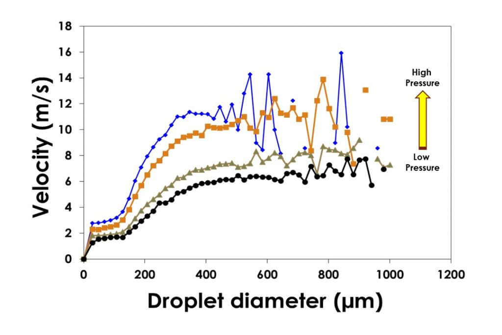
    One reason larger droplets still work well is due to the pre-orifice designs of modern low-drift nozzles. This design reduces the internal pressure of the nozzle itself, with the effect being a slower moving large droplet. This reduced velocity takes away some of the force at impaction, reducing rebound.

    Figure 7: Droplet velocity of larger droplets is reduced by lower pressures from pre-orifice and air-induced design nozzles. Lower velocities reduce droplet rebound.

    Another neat effect of coarser sprays is their ability to entrain air. All sprays move air (simply spray into a bucket to see this), and larger droplets do this better and for longer distances. The entrained air is a form of air assist for the smaller droplets, increasing their average velocity and thus reducing their drift potential while they move in the spray pattern. 

    The final stage of the dose transfer process is deposit formation and biological effect, and that’s where we once again see differences attributable to droplet size.

    Once established on a target surface, the active ingredient usually needs to move to its site of action. In some cases, resting on the surface is sufficient, it depends on the specific product. But for the majority of herbicides, the active ingredient must move across the cuticle into the cytoplasm where it eventually migrates to the enzymes involved in photosynthesis or biosynthesis of fatty- or amino acids.  The cuticle is waxy, with only a few water-loving pathways and the uptake process is basically driven by diffusion and concentration gradients. As such, it is more effective when the product is in solution and the longer the droplet can stay wet, the better.  That’s one reason why spraying during hot, dry days may reduce performance. Again, it depends on the formulation and the mode of action. Too high a concentration can damage membranes, physiologically isolating the active ingredient and reducing its subsequent translocation. It’s always a balancing act.

    If you’ve been keeping track of the score, it’s more or less a tie between large and small droplets. One deposits better and makes more efficient use of lower water volumes, while the other has lower losses from drift and evaporation, helps smaller droplets resist drift, and may improve uptake of some products.

    And this draw is why the venerable hydraulic nozzle has been so successful for so many decades. Hydraulic atomization, by its nature, creates a wide diversity of droplet sizes, ranging from 5 to 2000 µm or greater. As Dr. Ralph Brown of the University of Guelph used to say, this nozzle provides a drop for all seasons. Some small ones for coverage and retention in hard to reach places, and some large ones for uptake and drift-reduction. The result is a robust delivery system that provides reliable results on many different targets under many conditions. In recognition of the heterogeneity of sprays, we don’t refer to specific droplet sizes, but rather their composite, grouped into international categories of Spray Quality such as Medium, Coarse, and Very Coarse.

    Our challenge is to find the spray quality sweet spot, the ideal blend of these contradictory and yet complementary features of our agricultural sprays. And I believe that task is very achievable. Simply put, broadcast agricultural sprays in field crops work reliably when applied as Coarse and Very Coarse sprays in volumes between 7 and 12 US gpa. There is no need to spray any finer than Coarse for good efficacy, as coverage is already sufficient and any additional coverage has small marginal returns. There is, however, value in adding more water when canopies are denser or when leaf area index grows as the crop matures. To gain coverage, adding water is preferred to reducing droplet size because of the value of environmental protection. It so happens that Coarse to Very Coarse sprays provide or exceed the drift protection required by most agricultural labels.

    There is occasional reason for spraying even coarser than what I’ve suggested. It’s certainly required by law for dicamba products on Xtend traited soybeans and cotton, but even then, only in conjunction with higher water volumes to offset losses in droplet numbers.  In practice, moving to Extremely Coarse or Ultra Coarse sprays may allow an application to proceed in higher than average wind without adding drift risk. The use of some additional water is a relatively small price to pay for that additional capability.

    There will always be opportunities for efficacy improvement in specific cases for those willing to spend the extra time to optimize that situation. That’s one of the reasons I’m excited to see the widespread adoption of pulse width modulation (PWM) in the industry, allowing users to change spray pressure and therefore spray quality with no impact on application rate or travel speed. Or the introduction of nozzle switching from the cab, employing the optimal atomizer for a specific situation. Although it remains difficult to define the ideal spray, selecting a spray quality has never been so easy.