Sprayer math is important. It ensures the operator applies the correct product rate and has enough to complete the job. But, it assumes the airblast sprayer is behaving as expected… and it often doesn’t. After confirming the airblast travel speed, use one of the following methods to assess sprayer output. There are pros and cons to each.
The area method
Operators that claim the sprayer empties in the same place every time assume everything’s alright. They are performing a variation on the area method.
Essentially, you fill the sprayer with enough water to spray one hectare (or acre) and then spray that area. If the tank empties where expected, you know your output rate (i.e. volume / area). But, there are a few problems with this method:
Most operators don’t have an accurate test area marked off, and even when they think they know the area, measurements prove otherwise. They’re always amazed when this happens.
The area method has poor resolution. It reveals the total output but does not assess individual nozzles. For example, partially-blocked nozzles and worn nozzles average out (we’ve seen it). Rate controllers provide whatever pressure is required to match the desired output, masking individual nozzle problems.
The dip stick method
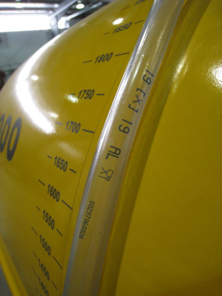
Another method is to fill the sprayer to a known volume using a flow meter, while observing a sight level or a graduated dip stick. Then, while parked, the operator sprays for a given amount of time and determines the difference in the volume remaining in the tank.
This method can be defeated if volume is misread. It’s an easy error to make if the sprayer is parked on a grade, or the dipstick shifts in a tank with a rounded bottom. And, of course, it also masks individual nozzle problems.
Sight levels can be misleading when the sprayer is parked on a grade. They are often opaque and hard to read.
The timed output method
The preferred method is to measure the output of each nozzle individually. We performed a review on several timed output methods here. It can be messy and time consuming, but it’s accurate. Appropriate personal protective equipment is required to perform the timed output method – expect to get wet.
1. Fill the rinsed sprayer half-full with clean water and park it on a level surface.
2. With the fan(s) off, bring the sprayer up to operating pressure. Start spraying with all nozzles open (closing any will change the pressure).
3. You will need 1 meter (3 feet) of 2.5 cm (1″) diameter braided hose (have a second, longer hose to reach the top of a tower sprayer). It should be stiff enough that you can slip it over a nozzle body while holding the other end. Use it to guide flow into a collection vessel, held with your other hand. The hose not only reaches the top nozzle on towers, but it lets foam dissipate before it gets to the vessel.
4. When the flow from the hose is steady, direct it into the collection vessel for 30 seconds (a partner with a stopwatch is very helpful). It is preferable to collect for a minute because it improves the accuracy.
5. Determine and record the nozzle output per minute. Graduations on plastic collection vessels are unreliable. It’s preferable to weigh the output on a cheap, digital kitchen scale. One milliliter of clean water weighs one gram. Don’t forget to subtract the weight of the vessel (this is called taring) and double the output if you only collected for 30 seconds.
Interpreting the results
Once you have recorded all the outputs, you will have to convert the output to U.S. gallons or liters per minute, depending on units in the nozzle manufacturer’s catalogue (see common conversions below).
Replace any nozzles that are 10% (or preferably 5%) more or less than the rated output. This not only indicates a rate problem, but likely a problem with droplet size as well. If enough nozzles are worn, consider replacing all of them. Nozzles should go on as a set, and come off as a set (unless replacing a broken tip, of course). This can be an expensive proposition for large airblast sprayers, but it is part of operational costs.
Don’t assume new nozzles are accurate. We’ve found +/- 5% flow variation right off the shelf. Keep your receipts.
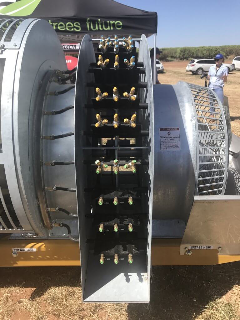
Testing and replacing nozzles is an important part of sprayer operation, no matter how many there are. This Air-O-Fan is nozzled for Australian almonds.
Helpful conversions
Anyone that has tried the timed output method in Canada knows the pain of our Metric-esque (Mocktric?) units. We’re an odd hybrid because our label rates are in metric, but our nozzles and many of our sprayers are US Imperial. You can find a complete collection of conversion tables here, but the most common calculations are reproduced below:
If collecting in ounces, converting to U.S. Gallons per minute:
If collecting in millilitres or grams converting to U.S. Gallons per minute:
If collecting in ounces, converting to litres per minute:
If collecting in millilitres or grams converting to litres per minute:
If collecting in ounces, converting to Imperial gallons per minute:
If collecting in millilitres or grams converting to Imperial gallons per minute:
A more sophisticated option
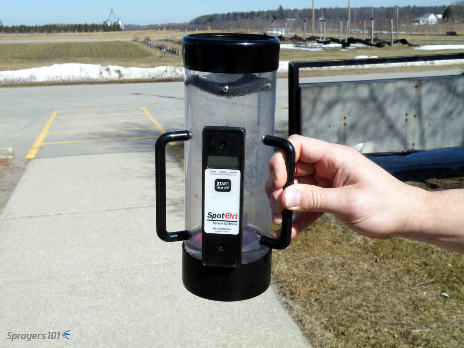
The timed output method is slow and requires math. You can avoid both problems by using electronic calibration vessels like the Innoquest SpotOn SC-4. We’ve tested both, and they are as accurate as weighing the output – but much faster.
They can, however, be fooled by foam. We’ve had good results using a length of braided hose to direct the flow and dissipate most of the foam. Typically, foaming means the sprayer wasn’t rinsed enough.
The SpotOn calibration vessel is easier, faster and more accurate than the classic pitcher-and-stopwatch approach to timed output tests. The SC-4 (pictured) is for airblast and SC-1 is for field sprayers.
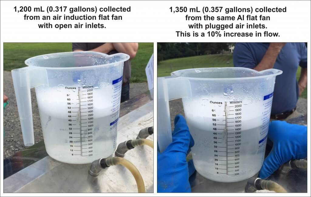
Another approach is to hose-clamp multiple hoses over nozzle bodies and spray all at once. This is tricky and takes time. Plus, if you suffocate the nozzle’s exit orifice (creating back pressure) or block the air inlets on AI nozzles, you will get a false reading.
Be careful not to plug air inlets on air induction nozzles – you may get a false reading.
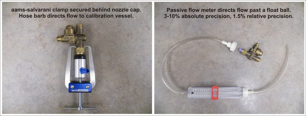
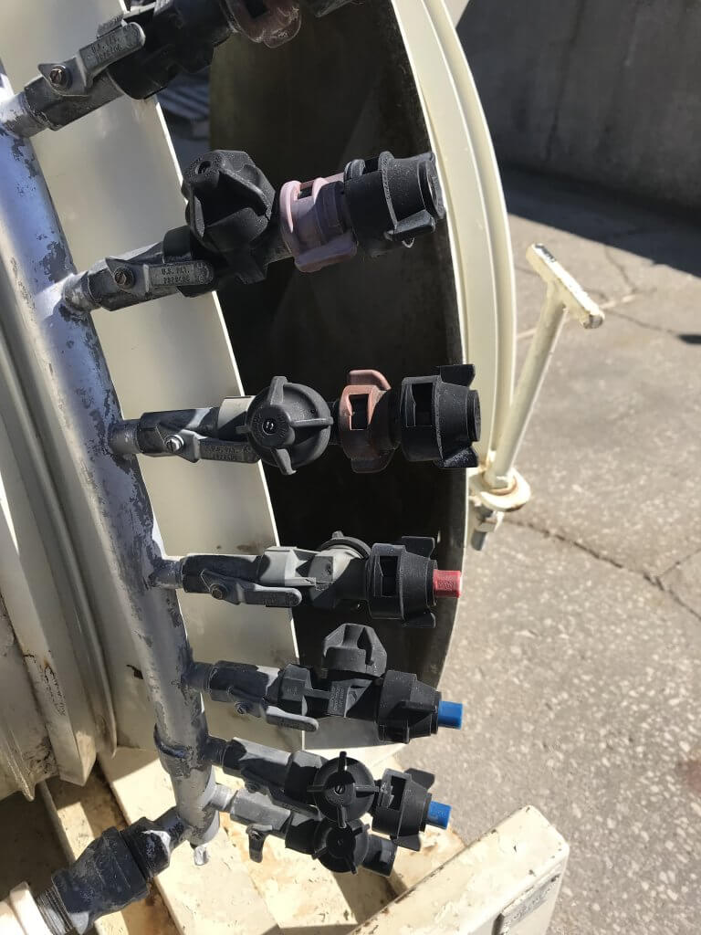
We prefer nozzle clamps over hose clamps (see the AAMS-Salvarani nozzle clamp pictured below). There are pincers designed to latch behind the nut of the nozzle body, but compatibility can sometimes be an issue (e.g. with Turbomist sprayers).
Passive flow meters (also pictured below) remove the need for a collection vessel, but they’re a better fit for field sprayers since they have to be held in place manually. They are difficult to source in North America because their accuracy is questionable, but they are fine for comparing relative flow from tip to tip.
Nozzle clamp or flow meter, avoid suffocating the nozzle exit orifice or AI nozzle air inlets.
Left: Nozzle body hose clamp. Right: Passive flow meter.
Some grower groups, or professional consultants, spring for very sophisticated and accurate units, such as AAMS-Salvarani flow measurement system pictured below.
AAMS-Salvarani flow measurement system. We used these on a pumpkin sprayer in New Hampshire, but they work with airblast too.
No matter your preferred method, take the time to confirm your sprayer output at the beginning of the season and whenever you make repairs or significant changes to your sprayer.
Excepting air shear and centrifugal style nozzles, most airblast sprayers employ nozzle bodies designed to except hydraulic nozzles distributed evenly along the booms. Nozzle caps compress the nozzle against the body to force the spray mix through the nozzle orifice. Nozzle bodies are not all created equal.
Double Outlet Roll-Over Nozzle Bodies
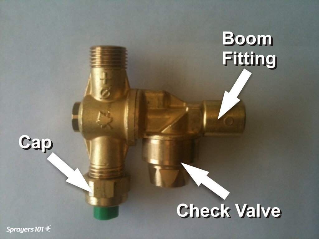
Double outlet roll-over bodies (pictured below) allow the operator to quickly switch between two nozzles mounted in each position. This is convenient when alternating from dilute to concentrated applications, or changing the spray distribution from block to block.
A typical brass roll-over style nozzle body with cap and check valve.
The roll-over feature can act as a shut-off and facilitate fine-tuning the orientation +/- 15° from centre. When roll-overs are new there is an audible ‘click’ when they reach 15° to alert the operator that turning them any further will interfere with flow. This feature fails as bodies wear.
Single Nozzle Bodies
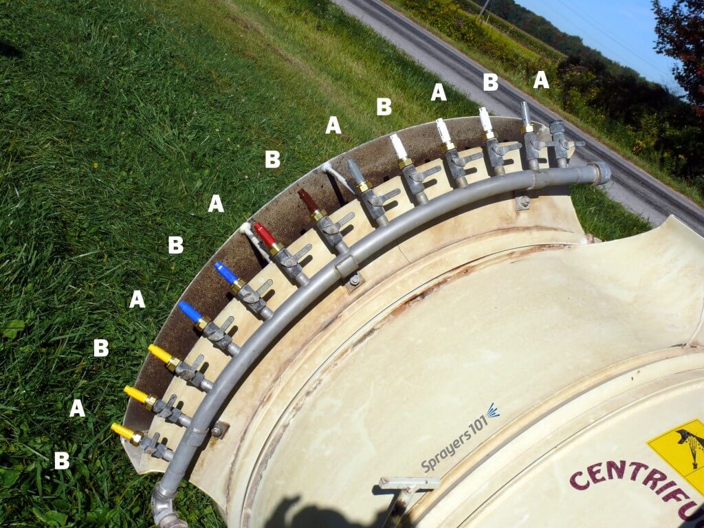
Some sprayers employ single nozzle bodies featuring screw or lever-style quarter-turn shut-offs. Some sprayers, like the Turbomist featured below, double the density of the bodies along the boom, arranged in an alternating A-B pattern. The operator shuts off each alternate nozzle, perhaps using the A’s for dilute and the B’s for concentrate applications. The density gives the operator the ability to “double up” in positions along the boom if more spray is required.
Some sprayers do not use double outlet roll-over nozzle bodies. Instead, they double the density of single bodies along the booms for use in an alternating A-B pattern.
Still others may affix the nozzle bodies to the deflectors (like the Air-O-Fan below), permitting the operator to orient the air and nozzles at the same time.
The Air-O-Fan offers double-density by affixing two single nozzle bodies to each air deflector. The operator aims air and nozzles simultaneously and can select flow combinations using quarter-turn shut-offs.
Check Valves
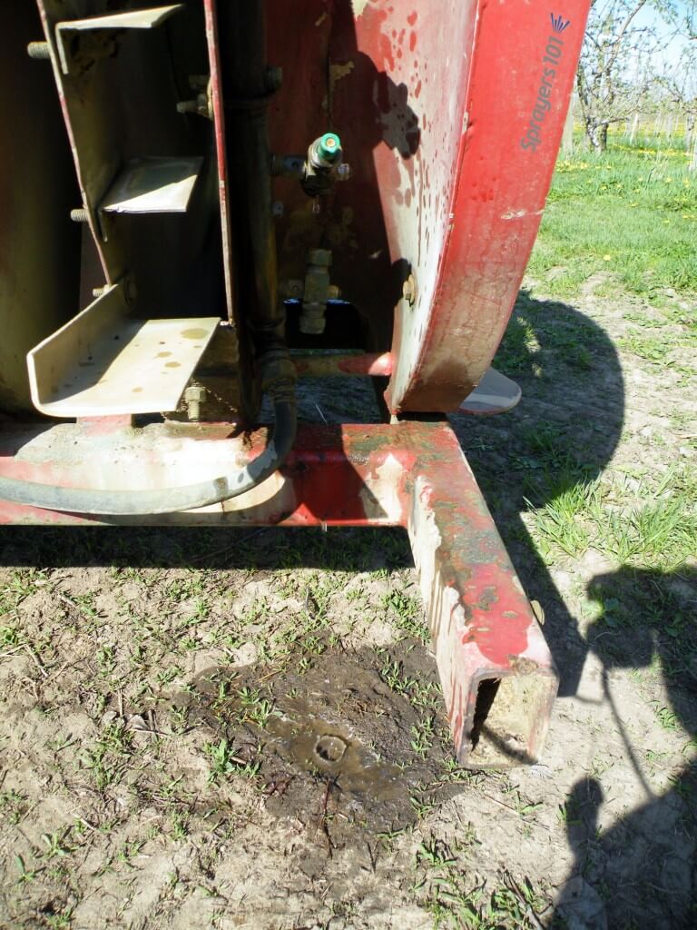
In my opinion, it should be mandatory for nozzle bodies (or at least booms) to have diaphragm check valves. When pressure drops below ~15 psi the valves shut to prevent the boom from draining (see image below).
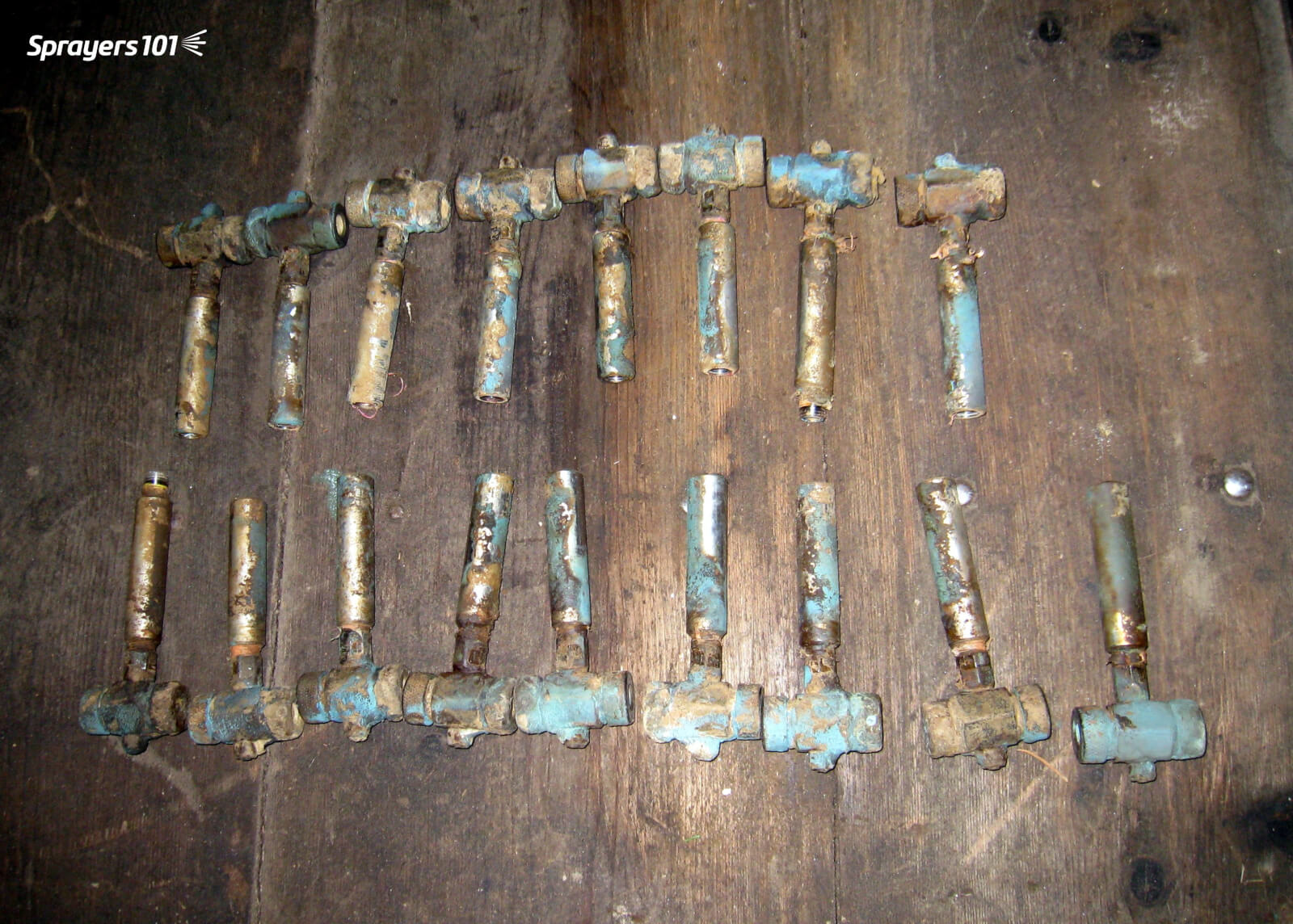
An older FMC with nozzles bodies that do not have check valves. Once the pressure is off, the booms drain through the lowest nozzle. This is a waste of pesticide and unnecessary environmental contamination.
Booms don’t just drain in the yard. Operators shut off the outside boom when turning at the end of a row. Without check-valves, the boom drains through the bottom nozzle, wasting pesticide and causing repeated and unnecessary point-source contamination. Further, it takes a moment for the boom to refill, meaning the top nozzles may not be spraying at the beginning of each row.
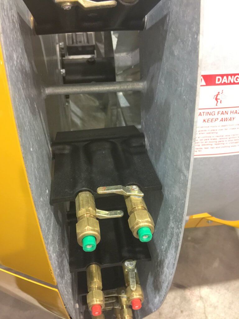
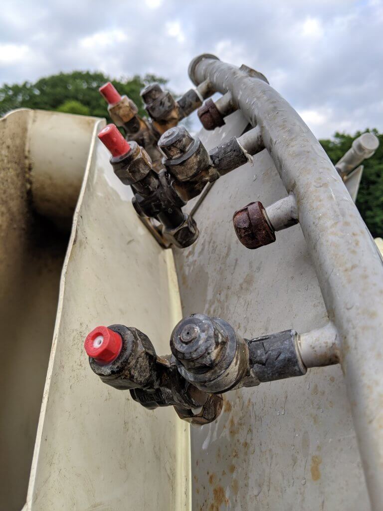
You may be tempted to purchase mesh nozzle strainers with built-in ball valves. They can work as an alternative to integrated nozzle body check valves, but they plug and fail with irritating regularity. The image below shows a creative method for installing check-valves on single nozzle bodies. The nozzles protrude and the check valve seems too close to the shut-off, but reputedly this works.
An example of retrofitting diaphragm check valves on single nozzle bodies.
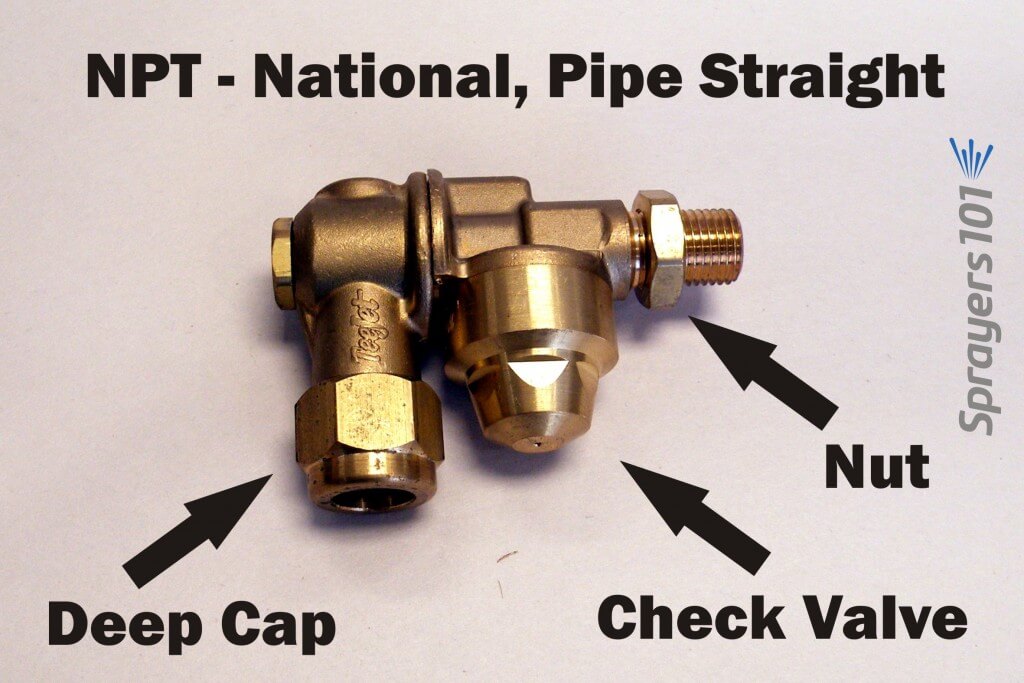
Thread Types
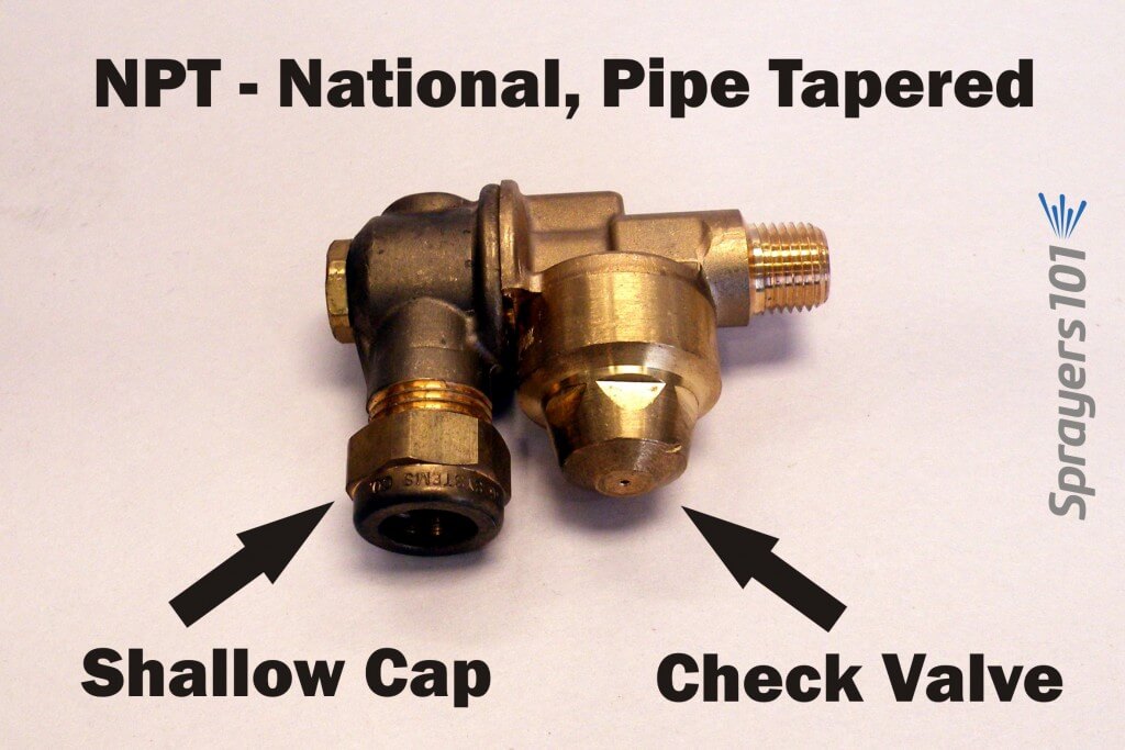
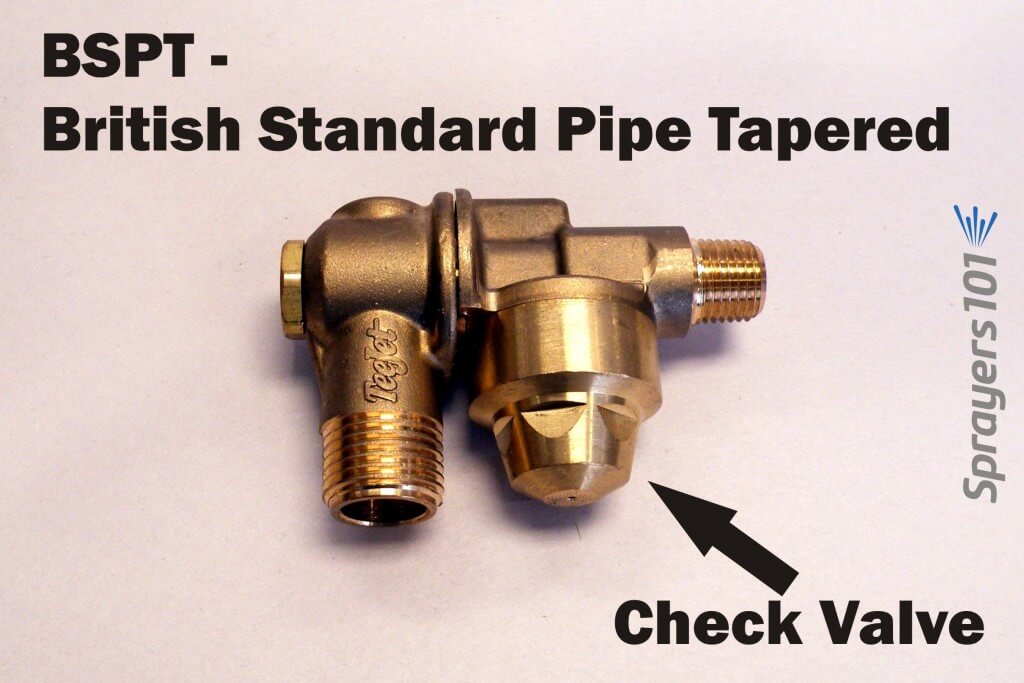
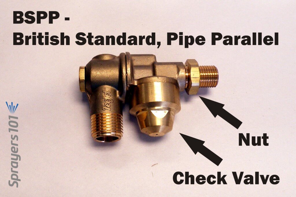
In North America, you will encounter four inlet thread types: NPT, BSPT, NPS and BSPP.
National, Pipe Tapered (NPT) single-sided, brass roll-over nozzle body with check valve. Note the shallow cap pictured here.British Standard, Pipe Tapered (BSPT) single-sided, brass roll-over nozzle body with a check valve.National, Pipe Straight (NPS) single-sided, brass roll-over nozzle body with check valve. Note the deep cap pictured here.British Standard, Pipe Parallel (BSPP) single-sided, brass roll-over nozzle body with a check valve.
The inlet thread sizes available are 1/4” female, 1/4” male and 3/8” male. 1/4” female is not available on the NPS or BSPP inlet thread types. If you are considering installing new roll-over bodies, know your boom’s thread type. The retrofitted Turbomist below, for example, required bodies with female fittings.
A retrofitted Turbomist with check valves and female double outlet roll-over bodies.
Molded Nozzles
Another reason for installing new bodies is to convert from disc & core combination nozzles to single-piece, molded nozzles. They may not fit existing nozzle bodies. Check the diameter of the body outlet (where the nozzle rests) and the outlet cap (which compresses the nozzle against the body outlet). Your sprayer may currently use an unusual-diameter nozzle, like older FMC disc & whirls or European large-diameter pink ceramic disc & cores. Today’s ISO molded nozzles won’t fit in those bodies, so you’ll need to replace them.
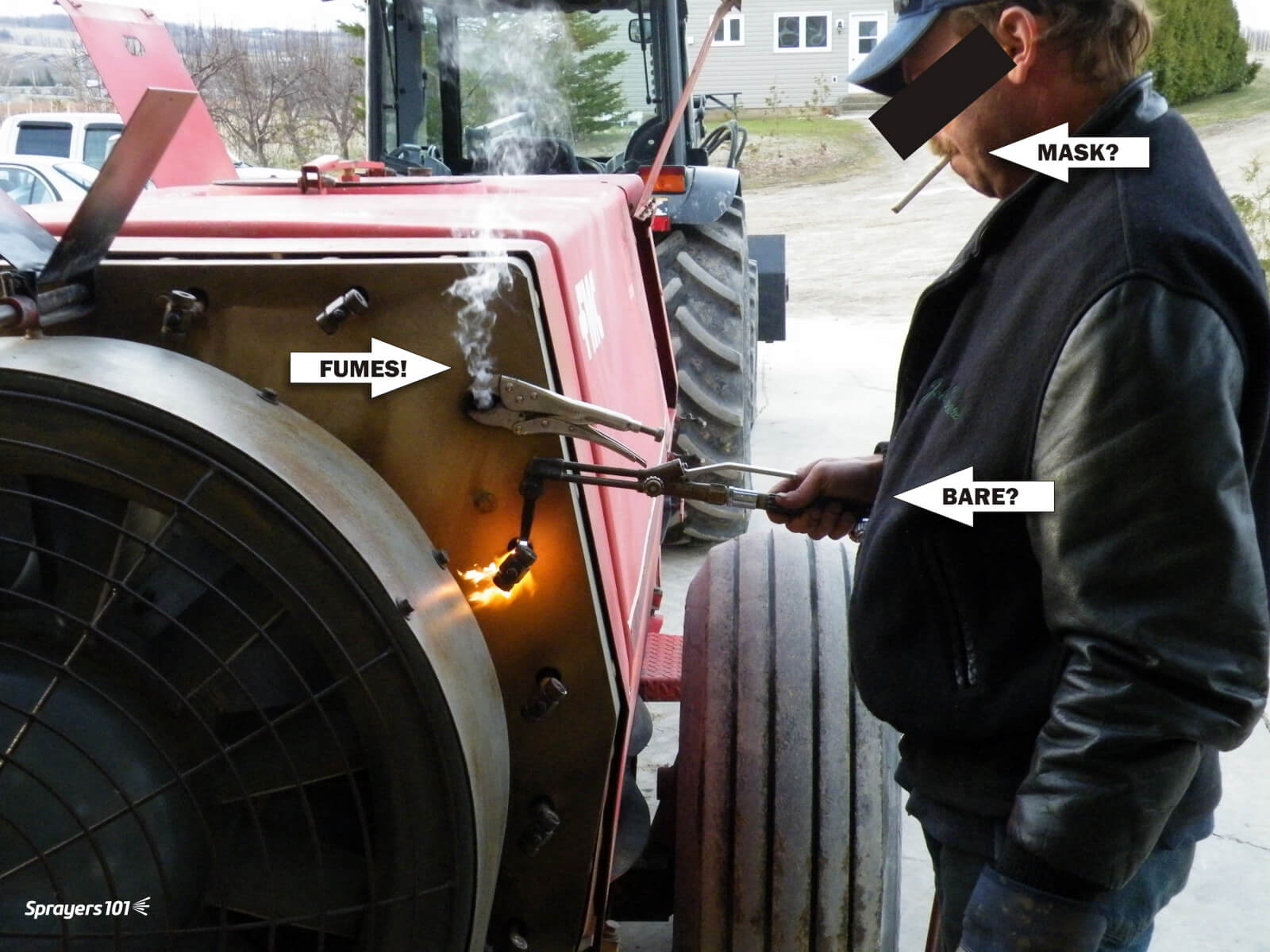
Old roll-over bodies without check-valves. These were removed to make way for better bodies.Older nozzle bodies can seize in the boom, requiring novel approaches to removing them. In this case, the mechanic is heating the fittings using “the blue wrench” to loosen them. If you do this, do not do what this mechanic did. Operate in an open space using gloves and a respirator. Years of residue build-up should be anticipated and respected.
Be aware: that unlike disc and core, molded nozzles protrude and may hit the edge of the sprayer duct when rolled over, preventing them from turning freely
Nozzle Body Caps
Nozzle bodies DO NOT come with the nozzle caps; they are specific to the nozzle type and must be ordered separately. This was an unpleasant surprise the first time I ordered a set of bodies.
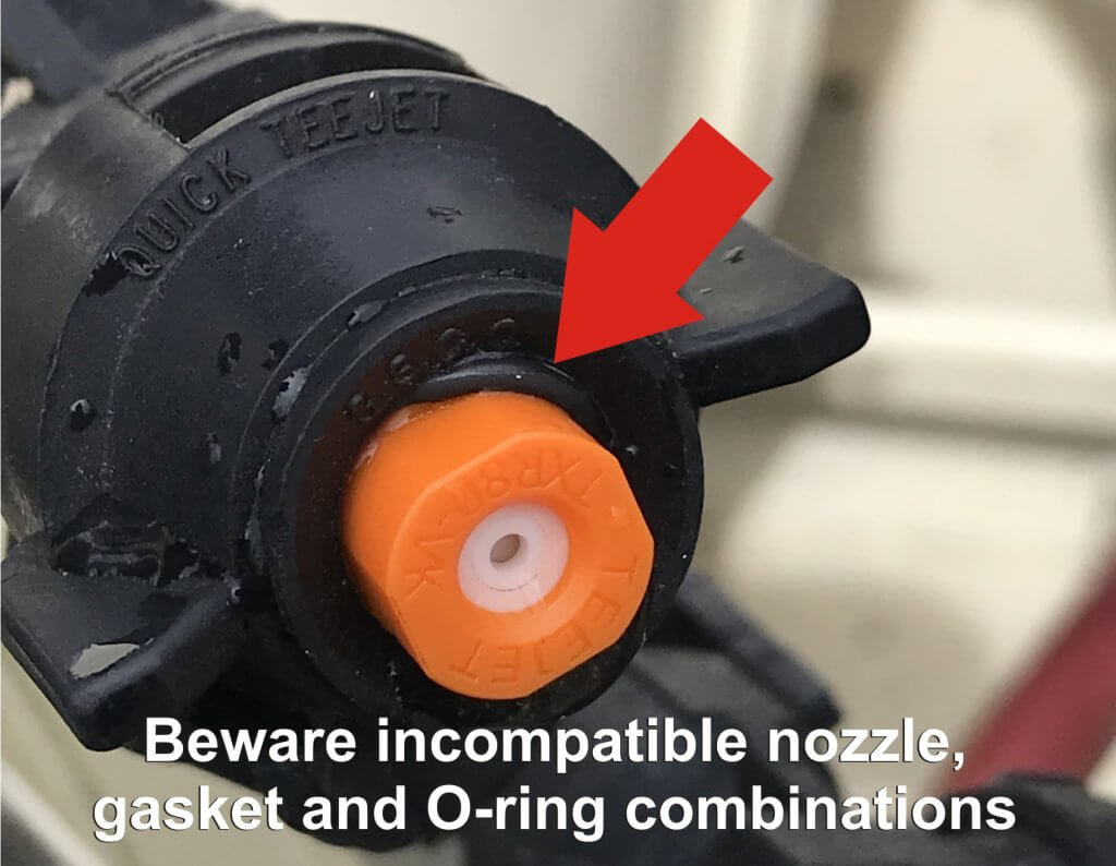
The standard caps are threaded brass hex nut-style but there are also nylon wing-style caps that don’t require a wrench. Beware converting to quarter-turn systems for airblast sprayers. It can work, but nozzles may require additional gaskets and O-rings… and even then are known to leak if the cap diameter is too large (see below):
Airblast pressure often exceeds 100 psi and can force the O-ring off the molded nozzle and cause leaks.
Be aware: North American nozzle caps might not fit imported European bodies, and European nozzles might not fit North American cap diameters. The LipCo sprayer is one such example.
Regarding the cap depths, sprayer operators must consider the how much “stuff” is between the nozzle body and cap. Gaskets, spacers, O-rings and strainers take up room that may warrant a deeper cap. Perhaps most critical is the nozzle itself. For example, brass disc-core are quite thin, but ceramic are much thicker. They require different cap depths.
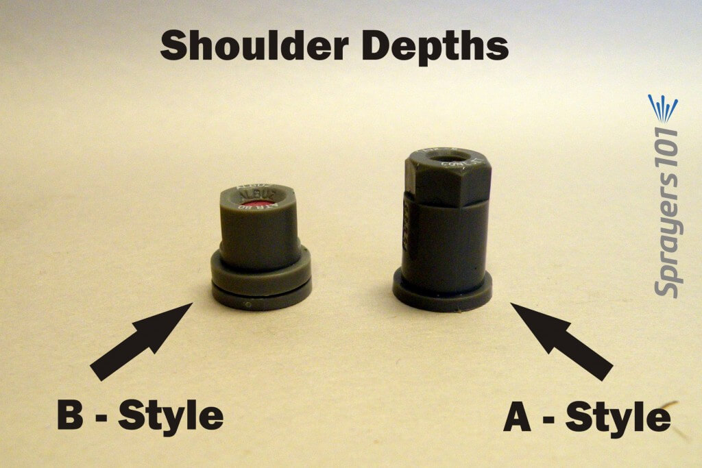
TeeJet’s molded cone nozzles come with an ‘A’ (Thinner) or ‘B’ (Thicker) shoulder. The shoulder is the lip around the nozzle base that is compressed against the nozzle body outlet. The B-shoulder is the ISO standard, and is preferred (see below). Shallow caps may not thread onto a nozzle body using a nozzle with a B-shoulder. Deep caps may bottom-out before compressing a nozzle with an A-shoulder, creating leaks. Be sure to note in the nozzle catalog which caps are recommended for the nozzle.
Molded cone nozzles come in the thin shoulder (A-style) or thick shoulder (B-style) varieties. The B-style is the ISO standard and is preferred.
Nozzle Strainers (aka Filters)
Before we wrap up, here’s one more look-out. As mentioned, the nozzle strainer shoulder takes up some room between nozzle body and cap. It turns out there can be another concern.
A hop grower contacted me. He had installed new nozzle bodies on his sprayer. He’d taken into account the shoulder depth and the cap depth. So why were his nozzles plugged? And why when he loosened the cap to finger-tight did they spray, but leak?
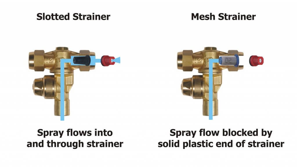
We tried gaskets, O-rings, different cap depths and new nozzles – but no change. That’s when we noticed one side of the roll-over body had a plastic slotted strainer and the other had newer mesh strainer. The mesh strainers were longer and terminated in a disk of solid plastic. When we swapped the two strainers, we had flow! We realized the longer mesh strainers were being compressed against the orifice in the nozzle body, acting like a cork in a wine bottle.
I prefer slotted over mesh because they are a bit more forgiving with dry formulations and hard water residue, but perhaps more critical is that they aren’t long enough to block the flow.
Be aware that some strainers may be long enough to block flow in the nozzle body.
Take Home Tips
If you are considering installing new nozzle bodies:
Confirm the male or female fitting and thread type of your boom
Ensure bodies have check valves
Ensure roll-overs and check valves clear any obstructions with nozzles in place
Know the nozzle type you intend to use, and ensure cap diameter is appropriate
Know whether you will use gaskets, o-rings, spacers and strainers, and confirm the cap depth will accommodate everything.
Be certain the strainer you choose isn’t so long that it interferes with flow.
Consider buying a single nozzle body to install as a trial before buying an entire set of replacements.
Some pesticide labels require or prohibit certain droplet sizes to reduce the potential for drift. But, even when labels are silent about size restrictions, operators should be aware of the potential for droplet size to affect coverage. In the case of airblast, droplets should be:
large enough to survive evaporation between nozzle and target.
small enough to adhere without drifting off course.
plentiful enough to provide uniform coverage without compromising productivity (e.g. affecting refills and travel speed).
Once spray leaves the nozzle, the operator has no more control over the application, so it’s important to plan for as many contributing factors as possible. Deciding which nozzles to use (and yes, you have alternatives beyond disc-core), requires an understanding spray quality symbols and basic droplet behaviour.
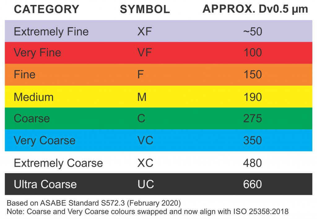
Spray Quality
Droplet diameter is measured in microns (µm). For a given pressure, a nozzle creates a range of droplet sizes which are described by the American Society of Agricultural and Biological Engineers (ASABE) standard S572.3 (Feb. 2020) In North America, these spray quality ratings range from “Extremely Fine – XF” to “Ultra Coarse – UC”. For interest, the scale is based on the British Crop Protection Council (BCPC) system, which is slightly different.
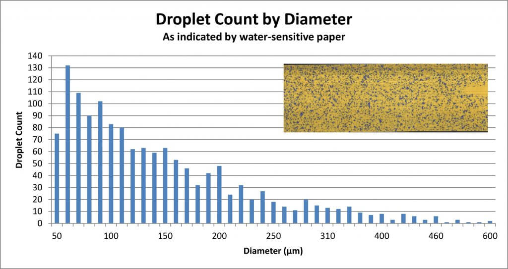
To make sense of the spray quality rating, we must first understand that not every droplet produced by a hydraulic nozzle is the same size. We noted that a single nozzle produces a range of droplet sizes. Spray quality captures that span using a few key metrics. The first is the Volume Median Diameter (VMD) or DV0.5. Think of it this way: Let’s say you have a hollow cone nozzle that breaks a volume of liquid up into droplets. Let’s arrange them from finest to coarsest as in the following graph.
The DV0.5 refers to the droplet size where half the spray volume is comprised droplets smaller than the DV0.5, and the other half is comprised of larger droplets. But we need more to understand the variation in the population. In other words, are they all the same size, or do they vary a great deal?
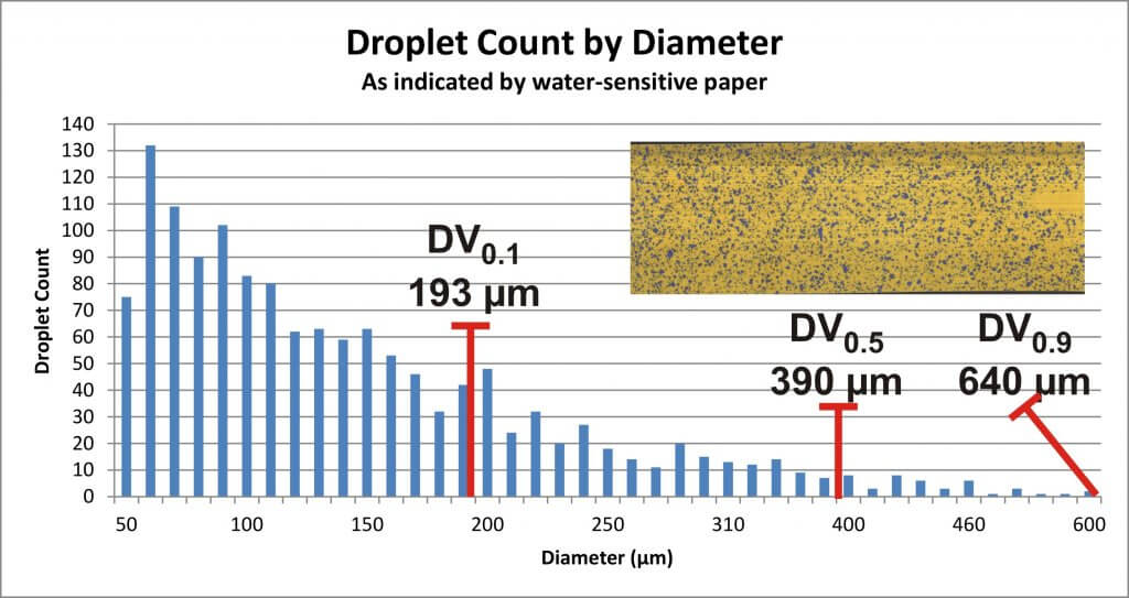
That’s why we also assign a DV0.1 which tells us the droplet size where 10% of the spray volume is comprised of smaller droplets, and a DV0.9 which indicates that 10% of the spray volume is comprised of larger droplets. Let’s add them to the graph:
With all three numbers, we can calculate the Relative Span (RS) by subtracting the DV0.1 from the DV0.9 and dividing by the DV0.5. The smaller the resulting number, the less variation there is in the spray quality. Two nozzles might produce a range of droplets with the same DV0.5, but the one with the larger RS is more variable, and is more likely to drift. Since we don’t typically have access to the RS of each nozzle, we rely on the spray quality symbols in nozzle catalogues to alert us to potential drift issues.
Relative Droplet Size
Did you notice in the graph that there are a lot of Fine droplets compared to Coarse? Disc-core (or disc-whirl) nozzles do not have spray quality ratings, and moulded hollow cones may or may not. This is, in part, because the standard was developed for flat fan nozzles, but mostly it arises from the nature of airblast spraying. No matter the original droplet diameter, the air shear from the sprayer and the distance-to-target reduce the DV0.5 considerably by the time spray reaches the target. It is safe to assume that the final spray quality will be much finer than the nozzle’s rating.
Incidentally, this is a big difference between boom sprayers and airblast: Where the boom sprayer operator should be aware of how pressure affects droplet size, it’s of little consequence to an airblast operator. On an airblast sprayer, pressure really only affects nozzle rate.
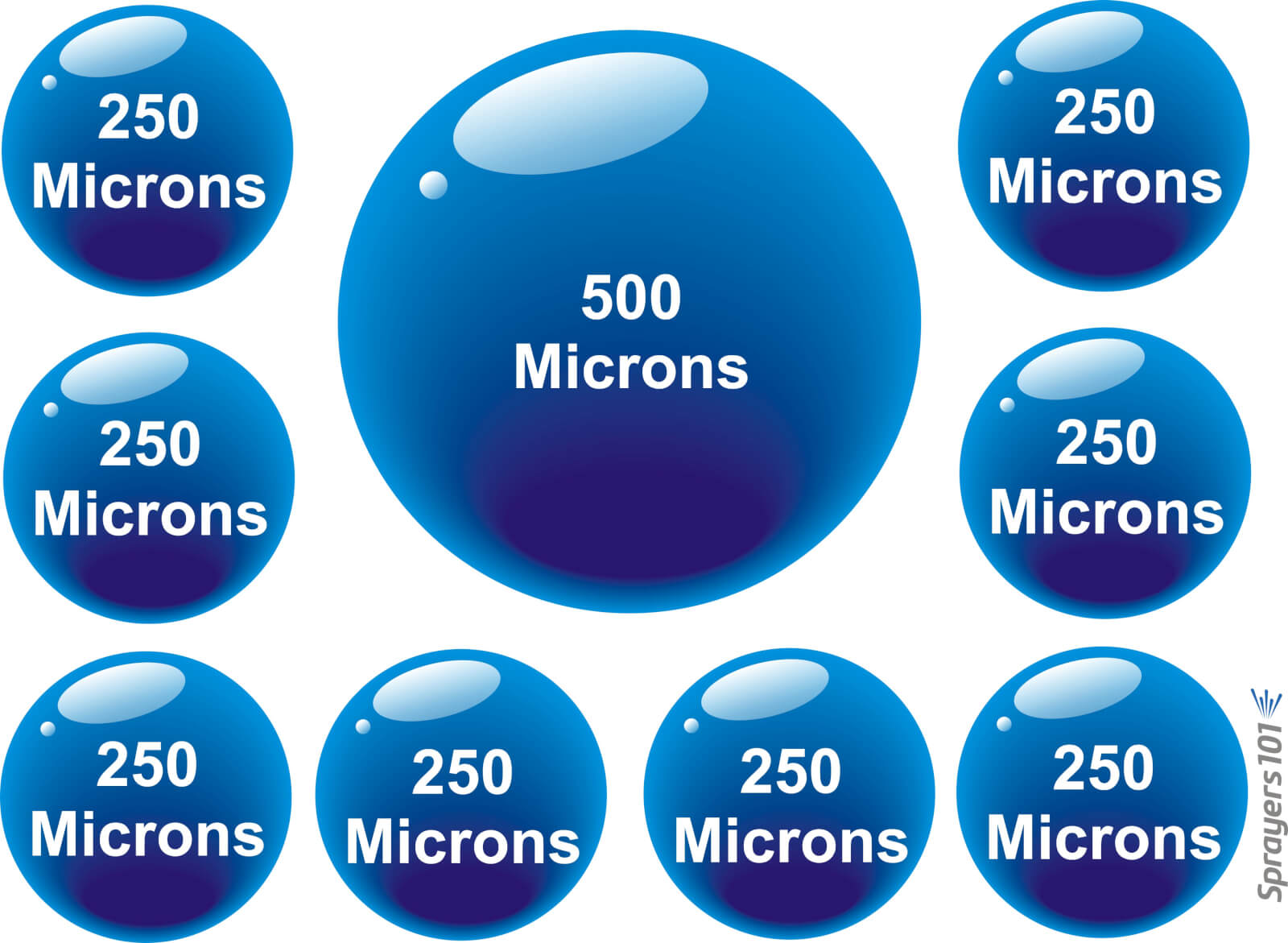
So, while shear and evaporation raise drift potential, shear also increases droplet count. Imagine the volume a nozzle emits as a cake. No matter how many slices you cut the cake into, you still have the same amount of cake. The finer the slices, the more people can have a slice, albeit not very much. Similarly, a single Coarse droplet can contain the same volume as many finer droplets. Mathematically, a droplet with diameter X represents the same volume as eight droplets with diameters of 1/2X. See the illustration below:
The eight to one rule: Every time the diameter of a droplet spray is doubled, there are eight times fewer droplets. Conversely, every time the diameter of a droplet is halved, there are eight times more.
Droplet Behaviour
The droplets that comprise the spray behave differently from one another. Finer droplets have a low settling velocity, which means they take a long time to fall out of the air. Conversely, coarser droplets fall out of the air more quickly. Think of how a ping pong ball (the finer droplet) has much less mass than a golf ball (the coarser droplet). When thrown into the wind, the golf ball follows a simple trajectory before falling. The ping-pong ball behaves erratically, like a soap bubble. Wind, thermals, humidity and many other factors will change where it goes because it is too light to resist them. It may even land behind the thrower, blown by the prevailing wind.
It is because of the behaviour of finer droplets, and the airblast sprayer’s inclination to create them, that we must be so diligent when we adjust the air settings.
We once explored this at a nursery workshop. The operator was spraying whips, which are young trees with very few lateral branches. He used a cannon sprayer to cover 30 rows (15 from each side) and felt he would incur less drift if he just used pressure, not air, to propel the spray. Water sensitive paper exposed the erratic coverage that resulted. Coverage uniformity was greatly improved when air was used, even when only spraying from one side of the 30 row block. Of course, this was only to demonstrate a principle; we don’t recommend alternate-row-middle-spraying.
Air-induction nozzles can be used to increase the median droplet size on an airblast sprayer. When used in the top nozzles positions, the coarser droplets that miss the top of tall targets will ultimately fall (reducing drift). They can also be used in positions that correspond to restricted airflow. In this case the operator relies on pressure to propel the coarser droplets where there is limited air to carry finer droplets.
Conclusion
The net result of all this is that the sprayer operator must choose a nozzle, pressure, and travel speed while considering the effect of distance-to-target and the weather. The resultant range of droplets should be fine enough to increase droplet count and be carried by sprayer air to deposit uniformly throughout the canopy. However, droplets should also be coarse enough to reduce drift if they miss.
Hey, if it was easy, anyone could do it!
Move ahead to 29:40 to watch a video describing how droplets behave an misbehave. Ahhhh Covid-hair. It was a thing.
ExactApply
is an application system capable of PWM, introduced by John Deere in August,
2017, with its first customer field season in 2018. ExactApply offers several
unique features that differentiate it from the existing systems. Here is a
brief description of its major components and capabilities:
Nozzle
Body Design:
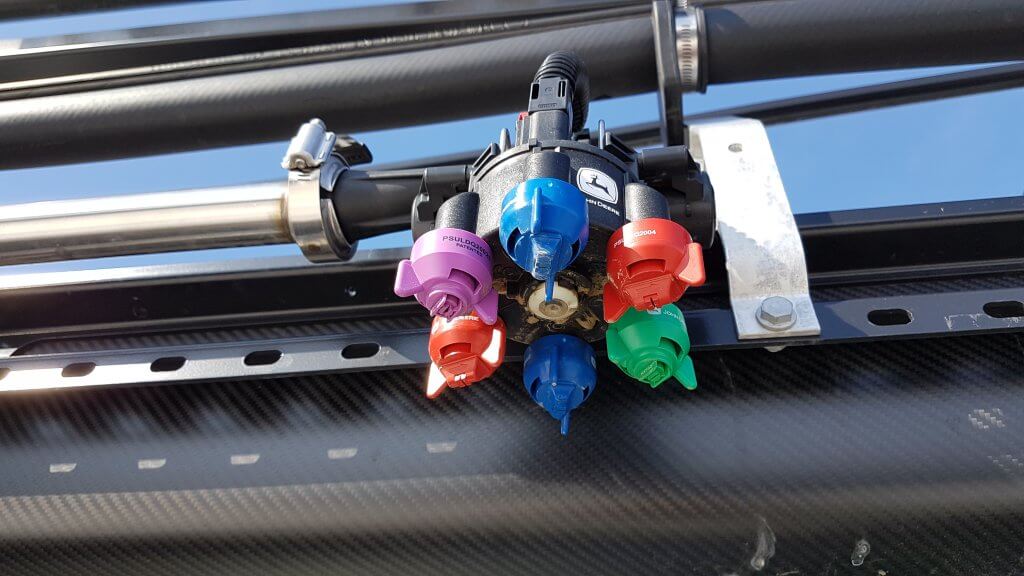
The body contains a turret with six numbered nozzle locations, all pointed down, and two solenoids, one on either side of the body. Three nozzle locations are on short feeds (locations 1, 2, and 3), whereas the remainder are on long feeds (4, 5, and 6). The front locations and left solenoid is called “A”, whereas the right solenoid and rear location is “B”.
ExactyApply nozzle body
Nozzles are paired so that A or B or both are capable of spraying at a time, depending on the selected mode. Pairs are 1 & 4, 2 & 5, and 3 & 6. The operator manually rotates the desired nozzle pair into position.
When a short feed (1, 2, or 3) is placed at the front of the body, the system is in Separated Mode. In this mode, the left solenoid controls the front nozzle and the right solenoid control the rear nozzle. Either or both can be used, in pulsing (PWM) or conventional mode, selected through the monitor.
When a long feed (4, 5, or 6) is placed at the front, the body is in Combined Mode. Now, all flow from the right and left solenoid can only exit the front nozzle. Very high flows are achievable in Combined Mode, making it suitable for liquid fertilizer application. It may not have other practical applications in Western Canada.
View from left side of body (solenoids removed). Turret position #4 (tall feed) is in front, and #1 (short feed) is in back, placing the body in Combined Mode.
In Pulsing Mode, each solenoid pulses at 15 Hz, meaning it completes 15 open-and-close-cycles per second. The A and B solenoid timing is offset by 180 degrees, so that the B nozzle is in the middle of its on-cycle when the A nozzle is in the middle of its off cycle. In combined mode, this means that the system operates at 30 Hz.
Adjacent bodies are also 180 degrees out of sync with each other, similar to Capstan, Raven, and TeeJet bodies, so that whenever a nozzle is off, its adjacent partners are on (when operating at 50% DC and above). Another way of saying this is that all even-numbered bodies act together, and all odd-numbered bodies act together but half a cycle later. This results in a blended pulse that prevents skips.
Plunger assembly inside solenoid. Black plastic portion can be removed, exposing poppet and spring.
The proportion of each cycle that the solenoids are open is known as the duty cycle (DC). At 100% DC, the valves are always open. At 50% DC, the valves are open 50% of the time. The minimum DC allowed by the system in default is 25%. This can be lowered to a smaller value within the monitor.
Opened plunger assembly showing tip of poppet (right) and seat (left)Poppet inside plunger assembly is pulled back by magnet inside solenoid 15 times per second
DC is closely related to the flow rate of the nozzle. There are two ways of looking at this. An 08 sized tip operating at 40 psi will have a flow rate of 0.8 US gpm at 100% DC, about 0.4 US gpm at 50% DC, and close to 0.2 US gpm at 25% DC. This feature is primarily useful when sprayer speed is changed, requiring new flow rates without a change in spray pressure.
Pulsing Mode is not available for nozzles sized smaller than 02, or for air-induced tips.
Pulsing can be disabled to allow the use of air-induced or other tip technologies that may not function well when pulsed. This is called AutoSelect Mode.
AutoSelect
Mode:
AutoSelect Mode (“Auto Mode” in 4600 monitor) can be used to achieve three unique flow rates. “A” alone, “B” alone, or “A” & “B”. When properly staggered, a travel speed range similar to Pulsing Mode can be achieved, although pressure will rise within each nozzle as travel speeds increase, as in a conventional system.
In AutoSelect Mode, the user selects a tip for position A, and an incrementally larger tip for position B. The monitor requires that the user inputs minimum and maximum pressures for A, B, and A&B. Travels speeds corresponding to these tip and pressure choices are calculated, and the monitor warns the user when speeds don’t overlap. The user either changes minimum and maximum spray pressures, or selects a different sized tip to eliminate the gap.
AutoSelect Mode is useful when a certain specific tip is required which is not compatible with Pulsing Mode, for example drift protection with air-induced tips.
Pulsing
Mode Nozzle Selection
At this time, John Deere nozzles best suited to the ExactApply’s Pulsing Mode are the LDM, LD, LDX, and 3D. Of these, the LDM most closely represents the spray quality of the LDA and ULD that John Deere operators are accustomed to. The remainder are considerably finer.
ASABE spray qualities for Low-Drift Max (LDM) tips. Being Very Coarse at lower pressures, applicators are advised to use higher spray pressures (50 to 70 psi) when coverage is important.ASABE spray qualities for Guardian (LDX) tips. Note that the smaller sizes (03, 04, 05) produce finer sprays and will require pressures below 40 psi to have any reasonable drift reduction. ASABE spray qualities for 3D tips. As with LDX, the smaller sizes (03, 04, 05) produce finer sprays and will require pressures below 30 psi to have any reasonable drift reduction. Such low pressures may narrow the spray pattern. ASABE spray qualities for Low-Drift (LD) tips. As with LDX, the smaller sizes (03, 04) produce finer sprays and will require pressures below 40 psi to have any reasonable drift reduction.ASABE spray qualities for the Low-Drift Twin (LDT). Comprised of two same-sized LD tips assembled in a TwinCap.
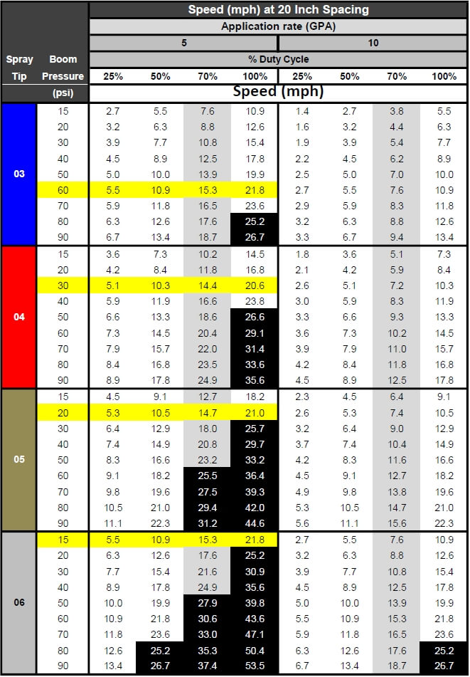
Proper sizing for PWM requires that tips be sized for about 20 to 40% extra capacity. In other words, at expected average travel speeds, the pulsing duty cycle should be approximately 60 to 80%. The following chart has a highlighted column at 70% duty cycle for that reason. Assuming an ExactApply operator expects to apply 5 gpa and travel at 15 mph on average, possible nozzle options (highlighted in yellow) are:
03 at 60
psi
04 at 30
psi
05 at 20
psi
06 at 15
psi
Calibration chart for PWM systems. Nozzles are sized at about 70% Duty Cycle (grey column). Options for 5 gpa at 15 mph are highlighted yellow. Black highlights represent speeds >25 mph, not available.
The best
choice will likely be either of the first two options, as the third and fourth
have spray pressures which are probably too low for good nozzle performance.
The decision would depend on the spray quality obtained for each of the
remaining two options.
Of
course, spray pressure can be altered to suit the operator’s spray quality
requirements. This merely affects the available speed range as well as the DC
at which the system operates at a given target speed, possibly affecting
Pulsing Mode utility.
The row of speeds adjacent to the selected nozzle and pressure identifies the approximate travel speed range that can be expected, from 25 to 100% DC.
It’s important to know your current DC to be sure the system is operating properly, and also to take full advantage of turn compensation features. We’ve described a way to place a DC display module on your home screen here.
The application volume can be changed to suit the specific use, the chart’s speed values are updated automatically. Make sure the nozzle spacing at the top left is correct for your sprayer
Pressure
Drop across Solenoids
PWM
solenoids represent a restriction to flow, and may cause a pressure drop. John
Deere has published the pressure drop, and it is shown in the above chart
(download version only). The pressure drop is fairly low, only 2 psi for an 04
tip operating in separated mode at 40 psi. For an 06 tip, the drop is 3 psi,
and for an 08, it’s 6 psi. a #10 tip has a 10 psi drop at 40 psi. These
pressure drops must be added to the operating pressure of the sprayer. Pressure
drop is important because the LDX, LD, and 3D tips will be operated at low
pressures to obtain coarse sprays for drift protection. Operating an 08 tip at
20 psi (at which pressure it has s drop of 3 psi) will result in in a tip
pressure of 17 psi. Since we are at the low end of a nozzle’s operating range,
pattern stability may be compromised when the drop is not taken into account.
Why 70%
Duty Cycle?
An operator of any PWM system needs to know their current duty cycle. On ExactApply, a module can be installed on the home screen that provides a visual display. We show how to do this here.
There are
five main reasons a nozzle should be sized to run at approximately 70% DC. The
first is to provide speed flexibility. An operator may need to speed up somewhat,
but usually not more than 30%. On the other hand, slowing down is much more
common to accommodate challenging terrain, and a factor of two to three is
possible (from 70% DC to 25% DC).
Secondly,
drift reduction through lower spray pressure usually requires less speed due to
the associated lower flow rate. With some DC room to spare, the loss of flow
can be corrected without requiring a speed change.
Thirdly,
spot spraying at a slightly higher rate is possible, again through DC alone.
Fourth,
Nozzle Rate Boost of up to 25% for up to six nozzle locations is possible
within the monitor, but only if the system is operating at 75% DC or less.
Finally,
turn compensation, during which the outside boom travels faster than the
tractor unit and the inside boom slower, requires this additional capacity.
More on turn compensation here.
AutoSelect
Mode Nozzle Selection
AutoSelect
Mode allows for three flow rates to be used in succession: A, then B, the AB.
The key to success is to use small size increments between A and B, and to use
tips that have a wide pressure range.
In the
example below, the A location was an 02 tip and the B was an 03, for a total of
05. Pressure was not allowed to drop below 30 psi to retain good patterns.
Pressure at switch over to the next largest flow rate therefore needed to be 80
psi to make the moves possible without pressure gaps resulting in
over-application. As a result, the spray quality can be expected to fluctuate
three times as the sprayer accelerates through A, B, and AB in succession.
Nozzle
selection should seek to emphasize the middle of the pressure range of either B
or AB to avoid unnecessary fluctuations.
Spray pressure and travel speed as Auto Mode moves through A, then B, then both A&B
Download an Excel sheet that assists in nozzle selection for Auto Mode here.
A
maintenance kit comes with each ExactApply sprayer. It contains two spare
plunger assemblies, clips, and pins, as well as a brush, an O-ring picker, and
a torque driver.
Maintenance kit
The
ExactApply body is fairly easy to take apart for servicing. Hair pins at the
back of the unit secure each solenoid, and both pull out easily. The plunger
assembly can be disassembled without tools. Take care not to drop the poppet
spring!
Reassembly
of the plunger requires the use of the torque driver fitted with a 17 mm
socket, included in the kit. Do not over-tighten the plastic component.
Aside
from the manual rotation of the turret to select a different nozzle
combination, the only moving part in the ExactApply body is the poppet in the
plunger assembly. This piece is the valve that controls flow rate, and opens
and closes 15 times per second whenever pulsing mode is on, moving like a
piston in a cylinder. Debris (sand, fertilizer crystals, etc.) can interfere
with the seal of the poppet against its seat, and good filtration is important.
In the first generation, metal flakes began appearing inside some plunger assemblies . A coating de-laminates off the sleeve and can cause the plunger to stick. This has been starting at 800 h of use. The springs have also been observed to break. This problem has been addressed in newer generations.
Metal flakes interfering with plunger actionPlunger damage showing likely source of metal flakesBroken plunger spring
Certain formulations may build up a residue that interferes with poppet movement. It’s impossible to predict all possible formulation impacts, but oily formulations such as emulsifiable concentrates (EC, milky appearance) are likely to be more problematic than solutions (S, clear appearance). John Deere recommends a daily rinse of the boom through both the A and B valves with Erase, a tank cleaner product. Fortunately, the R series sprayer allow for boom flushes from the clean water tank even when the product tank has product in it.
Each nozzle body contains ten O-rings and two sets of seals. The turret assembly has two large rings, and each plunger assembly has four. Care needs to be taken to prevent damage to these rings to prevent leaks.
O-rings in nozzle body
Some
Recommendations
The
ExactApply system is very full featured and customers new to PWM can be
overwhelmed by the number of choices at their disposal. Let’s simplify the
system and make some basic recommendations.
Pulsing mode is likely to be the most useful feature of the system. Plan to use this feature for most spraying operations.
In Pulsing mode, select from John Deere’s LDM, LDX, LD, and 3D tips. The LDX, LD, and 3D offer similar Medium spray qualities and should be operated between 20 and 40 psi to produce lower-drift sprays. Check spray patterns at these pressures and ensure that 100% overlap is achieved (pattern width is twice nozzle spacing).
The LDM (Low Drift Max) is coarser than the above nozzles (comparable to ULD or LDA) and is available in 03, 04, 05, 06, 08, and 10 sizes. This will be the tip of choice for pulsing mode and can be used at higher pressures to ensure good pattern formation.
Separated mode can handle most flow rates, and offers the flexibility of choosing A (front tip) or B (rear tip) or both. This means turret 1, 2, or 3 will be in the forward (A) location.
Equip the A location with your low volume tip (say, 5 gpa). Place the high volume tip (say 10 gpa) at the B location. Use both together for late season sprays into dense canopies (in this case, A&B=15 gpa)
Twin tips for Fusarium Head Blight (FHB) can be achieved in five different ways.
3D tips in “A” or “B”, alternating their orientation along the boom (forward, backward, forward…). Pulsing Mode. (Since these tips are not very coarse, low pressures are needed to ensure that the angle of the spray persists more than a few inches).
3D tips in “A” and “B” on each body, front facing forward, rear facing backward, and operating in A&B. Pulsing Mode.
LDT (Low Drift Twin) in “A” or “B”. LDT is a TwinCap with two LD tips installed. Pulsing Mode.
LDM (Low Drift Max) in installed in a TwinCap in “A” or “B”. These are coarser sprays that will retain their direction longer and are well suited for FHB. Pulsing Mode.
GAT (GuardianAIR Twin), an air-induced tip, running in either conventional “A” mode or in Auto Mode but sized for “B” (avoid operating in A&B to prevent pattern interference).
Some recent recommendations: A customer wanted tips for 5, 10, and 15 gpa at 14 mph, and the 15 gpa was for FHB. He didn’t want to be too coarse. We recommended the LDM 03 at 60 psi (5 gpa) in “B”, the 3D 08 at 30 psi (10 gpa) in “A”, and both together, with the 3D facing forward, for FHB for 15 gpa. The sprays would be “Coarse”, a nice middle ground.
ExactApply joins Capstan PinPoint II, Raven Hawkeye, and WEEDit Quadro, Agrifact StrictSprayPlus, and TeeJet DynaJet with PWM capable systems. Auto Mode is a version of nozzle switching first introduced into the market as Arag Seletron and Hypro DuoReact. It appears to be a full-featured system that is fully integrated into the new John Deere 4600 display but is also available as a retrofit on the older R-Series 2630-equipped sprayers.
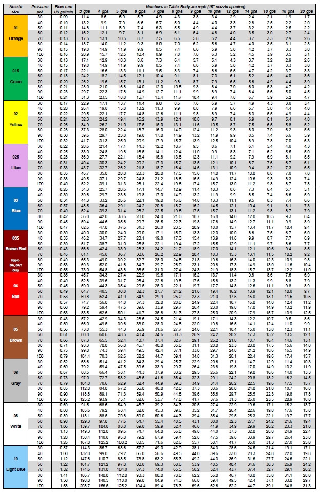
Need to find the right nozzle size for your application? Sometimes a simple chart is the easiest way to figure things out. Print it and place it in your sprayer cab.
In this chart, identify your water volume along the top row, and follow the column until you encounter the travel speeds you’re interested in.
Once you’ve encountered your travel speed, move along the row to the left to identify the nozzle size and spray pressure.
Make sure that your travel speeds are achieved at a pressure that’s right for the nozzle you’re using. For most air-induced nozzles, this will be about 60 to 70 psi (highlighted).
Once you’ve decided on a nozzle size, the travel speed column for that size becomes the travel speed range at various pressures. Avoid operating a low-drift spray below 30 psi – its pattern will be too narrow and likely its spray quality will be too coarse for good results.
Click on the images or text below to download a high quality pdf version of each chart, starting from the top with US, 15″ spacing, then US, 20″, then US 30″, then metric, 50 cm. Print, laminate, and place them in your sprayer cab.