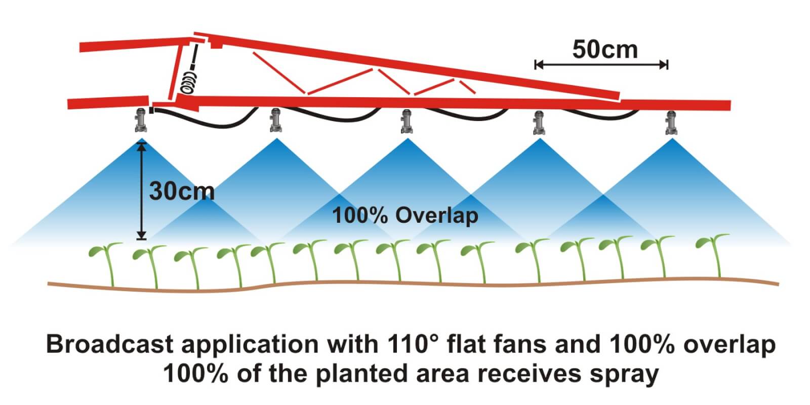
Where crops are planted in rows, growers can save on chemical costs and reduce potentially wasted spray by performing banded applications. A banded application is treating parallel bands (Figure one), unlike a broadcast application where the entire area is treated (Figure two). This means only a portion of the field or orchard/vineyard floor receives spray, so the total amount of product applied per hectare (or per acre) should be less for banded than for broadcast.

Banded applications are used in many situations, including:
- Applying herbicides right over a crop during planting, both for pre-emergent or post-emergent crops.
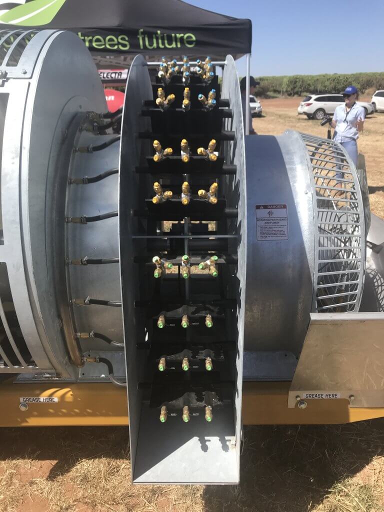
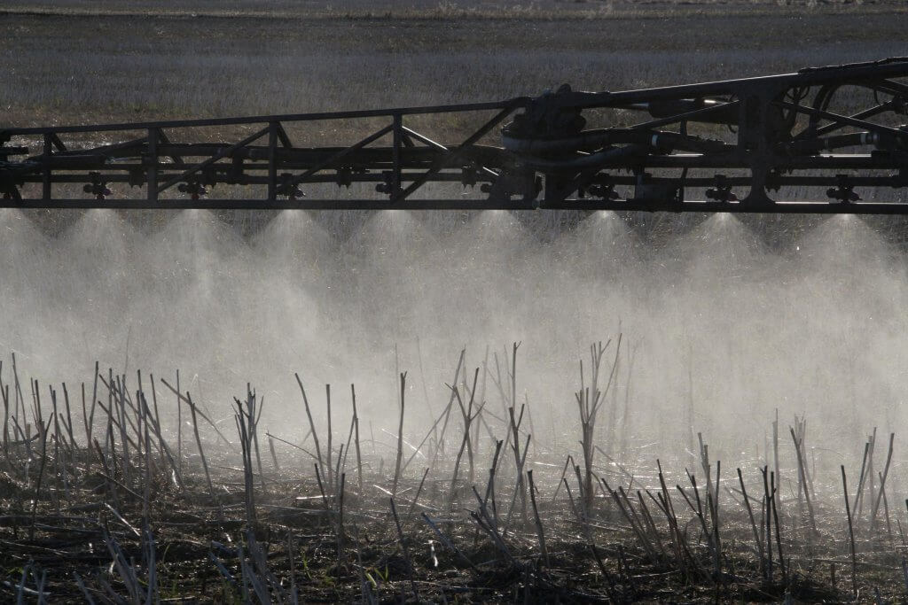
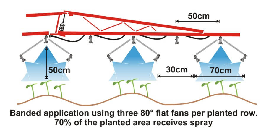
- Applying insecticides/fungicides by “directed spraying” using drop hoses or row kits; the latter is pictured in Figure three.
- Carefully spraying herbicide between the rows to control weeds in the alleys of an established crop (Figure one).
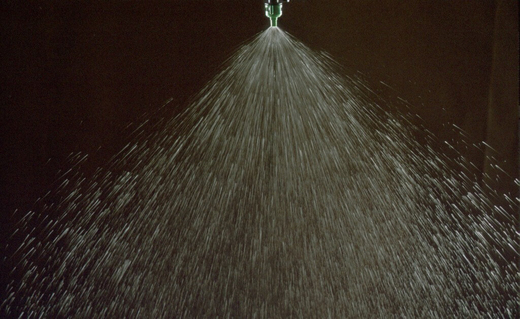
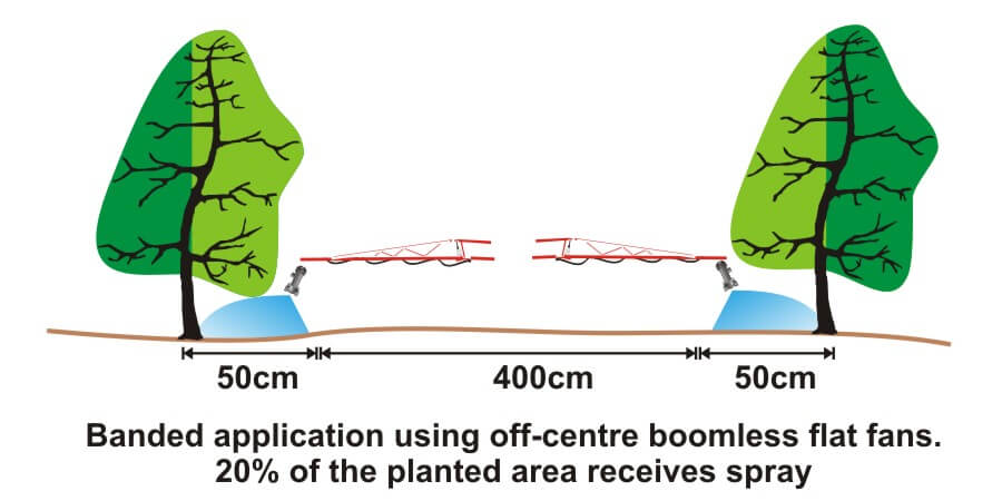
- Applying herbicide under fruit trees or grape vines to control weeds (Figure four).
It’s easy to make mistakes when calculating product rates for banded applications and these can be costly errors: too little means poor control and too much means wasted product and possible crop injury. This article describes how to calculate sprayer output and product rate for common banded applications.
Step One: Determine broadcast volume
Pesticide labels typically list broadcast product rates (e.g. amount of formulated product per hectare or acre). In this example, let’s say the label recommends a broadcast product rate of 500 ml of formulated herbicide applied using 100 litres of spray mix per hectare (i.e. added to 99.5 L water).
Step Two: Establish sprayer settings
Select a travel speed that is safe, gives decent efficiency and doesn’t compromise coverage. For this example, we’ll say the sprayer moving is at 8.0 km/h.
Select a band width that completely covers the target row and some of the adjacent area where control is desired. Band width should be measured along the ground for soil-applied products or along the top of plants for post-emergence products. We’ll use Figure one for our settings: bands are 50 cm wide on 100 cm centres. We’ll say that a single nozzle swath can treat the band, and that we’re spraying 2 hectares of planted area.
Step Three: Calculate the banded sprayer output
We can calculate how much of the planted area actually receives spray using this formula:
[band width (cm) ÷ row width (cm)] x total planted area (ha) = actual sprayed area (ha)
[50 cm ÷ 100 cm] x 2 ha = 1 ha
For completeness, here’s the US formula:
[band width (in) ÷ row width (in)] x total planted area (ac) = actual sprayed area (ac)
From this we now know that we should be able to go twice as far on a tank spraying a banded application as we would a broadcast, because we’re only spraying half the planted area.
Step four: Calculate the nozzle output
Use the following formula to convert the broadcast output into the banded output:
[broadcast output (L/ha) x travel speed (km/h) x (swath width (cm) ÷ number of nozzles per swath)] ÷ 60,000 = nozzle output (L/min)
[100 L/ha x 8 km/h x (50 ÷ 1)] ÷ 60,000 = 0.67 L/min
For completeness, here’s the US formula:
[broadcast output (gal/ac) x travel speed (mph) x (swath width (in) ÷ number of nozzles per swath)] ÷ 5,940 = nozzle output (gal/min)
If multiple nozzles were contributing to the swath, such as in figure three or figure four, this formula will account for it. You still mix the labelled product rate at a ratio of 500 ml of herbicide to 99.5 L water, but as we determined in step three, we should be able to spray twice the planted area using a banded application as we would a broadcast application.
Warning! Watch your units. You may be familiar with other formulae for calculating your output. Do not mix and match formulae or parts of formulae. For example, here is another Metric option for determining L/min. It employs different units so it requires a different constant:
[broadcast output (L/ha) x travel speed (m/min) x (swath width (m)) ÷ number of nozzles per swath)] ÷ 10,000 (m2/ha) = nozzle output (L/min)
Step Five: Use the nozzle catalogue to find the right nozzle
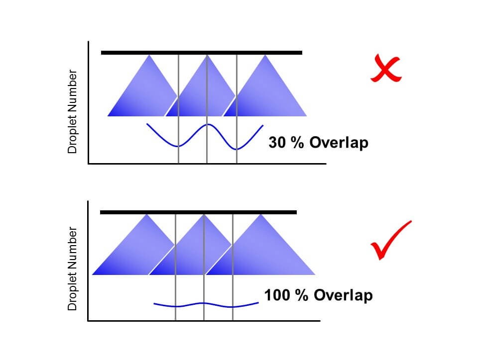
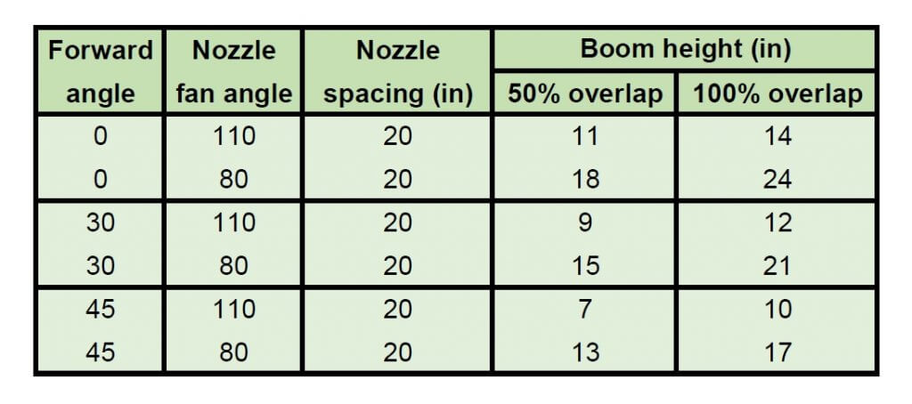
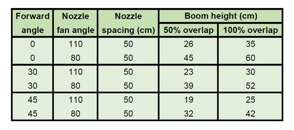
Using a nozzle manufacturer’s catalogue, select a nozzle that gives the desired spray quality (usually coarser for herbicides) and will produce the 50 cm swath we’re looking for (which can be adjusted a little using boom height). Always choose to operate a nozzle in the middle of its pressure range.
Step Six: Calibrate the sprayer (i.e. double-check)
Follow your typical calibration process and make minor adjustments until the nozzle discharge per minute results in the desired banded output. A rate controller will handle this on larger sprayers, but if you don’t have one you can make small adjustments to speed and pressure until the desired output is achieved. Ideally, if your math was right, these changes won’t be needed.
When performed correctly, banded applications are a great way to focus your efforts on the target, saving time and money.
Here are a few additional resources if you’d like to learn more, or work with a few online calculators: