Category: Calibration
Horizontal boom sprayer calibration
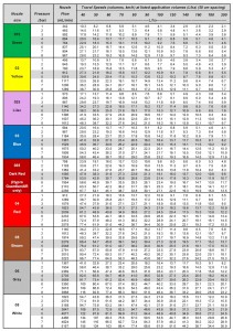
Nozzle Sizing and Calibration Charts
Need to find the right nozzle size for your application? Sometimes a simple chart is the easiest way to figure things out. Print it and place it in your sprayer cab.
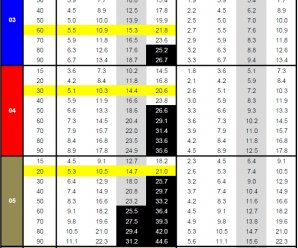
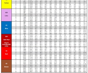
In this chart, identify your water volume along the top row, and follow the column until you encounter the travel speeds you’re interested in.
Once you’ve encountered your travel speed, move along the row to the left to identify the nozzle size and spray pressure.
Make sure that your travel speeds are achieved at a pressure that’s right for the nozzle you’re using. For most air-induced nozzles, this will be about 60 to 70 psi (highlighted).
Once you’ve decided on a nozzle size, the travel speed column for that size becomes the travel speed range at various pressures. Avoid operating a low-drift spray below 30 psi – its pattern will be too narrow and likely its spray quality will be too coarse for good results.
Click on the images or text below to download a high quality pdf version of each chart, starting from the top with US, 15″ spacing, then US, 20″, then US 30″, then metric, 50 cm. Print, laminate, and place them in your sprayer cab.
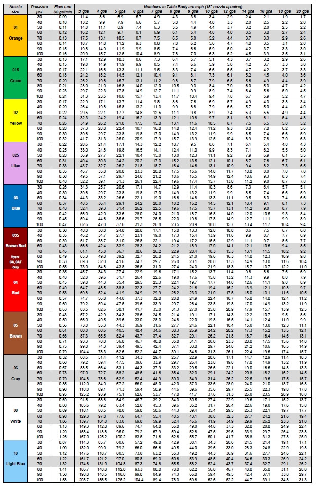
Download Application Chart (US units, 15″ spacing)
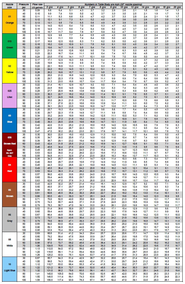
Download Application Chart (US units, 20″ spacing)

Download Application Chart (US units, 30″ spacing)
Download Application Chart (metric, 50 cm spacing)
Make your own chart using this Excel Template.

Pulse Width Modulation For Newbies
I was recently asked to describe Pulse Width Modulation to a non-farming audience. My instinct was to send them back to what we’d already written about the topic on Sprayers101, here and here. But on reviewing the material, I soon realized that most of our posts assume a certain amount of basic knowledge and understanding. What about people who are new to the business, or just curious? Not that helpful.
This is the first in a series of articles that cover off topics which may be too basic for many, but are nonetheless important for others. More to come. And suggestions welcome.
Sprayers are used to apply crop protection agents to fields, and as with all crop inputs, it’s important to apply the correct dose. For boom sprayers, dose is a product of the swath width, the sprayer travel speed, and the flow rate of spray liquid through the nozzles. Of these three factors, swath width is taken as constant, whereas travel speed and flow rate are variable. If travel speed changes, flow rate also needs to change to maintain the target application rate.
The vast majority of nozzles come in fixed sizes. As a consequence, the only way to change their flow is with spray pressure. In a modern sprayer, a computer known as a rate controller takes care of the math and the adjustments. For example, if the sprayer speeds up, it will need to deliver more liquid to keep the same application volume per acre. The rate controller knows the swath width (entered by the user) and senses travel speed (using radar or gps) and liquid flow rate (using a flow meter). If the travel speed increases, the rate controller causes the spray pressure to increase until the flow rate sensor shows that the flow is enough to maintain the target application rate.
The problem with this approach is that sprayer nozzles are very sensitive to spray pressure. Too low a pressure will cause the spray pattern to deteriorate, resulting in poor coverage. Too high and the spray will become too fine, creating drift problems. As a result, traditional sprayer operators have to stay within a very specific, narrow speed range. This may not always be possible if, for example, the terrain is hilly or the soil is wet.
One solution to this problem is to control flow rate differently. A fairly new way to do it is with Pulse-Width Modulation (PWM). This is a fancy term that describes a well established way that liquid flow rates are controlled in a number of other tasks such as fuel injection or hydraulic oil systems.
With PWM, each nozzle body is equipped with an electronic solenoid (shut-off valve). The valve turns on and off ten or more times every second, creating an intermittent, pulsed spray. The number of times the valve cycles on and off per second is called the frequency, measured in Hertz (Hz), cycles per second. The proportion of time that the valve is open, called the pulse width or duty cycle, is related to the liquid flow rate passing through the nozzle. Duty cycle can be electronically controlled.
For example, each nozzle can operate at its full rated flow (100% duty cycle) or a fraction of its flow (say 20% duty cycle). At low frequencies (about 10 to 15 Hz, common in PWM systems) duty cycle is proportional to the flow rate of the nozzle. At 20% duty cycle, the nozzle delivers about one fifth of the flow compared to 100%. The pulses are so quick that it doesn’t affect overall coverage or droplet size. With this system, as a sprayer speeds up or slows down, the duty cycle changes automatically to match the flow rate requirements calculated by the rate controller.
What does this mean in practice? For one, the sprayer no longer relies on a pressure change to influence the nozzle flow rate because duty cycle has taken over that job. In fact, the operator can set the pressure to whatever is necessary for best coverage or best drift control, whatever is most important. A change in travel speed caused by a hill or a slippery spot doesn’t affect pressure any more. The end result is a spray application that is not only more accurate, but also more consistent over varying conditions.
Drift control is easier with a PWM system. A common way to reduce drift is to make the spray coarser, and this can be achieved with lower spray pressure. But lowering the pressure results in less liquid flow, and the operator has to slow the sprayer down if the same application rate is to be maintained. With a PWM system, the operator simply lowers the pressure. The system makes up for the lower flow by internally increasing duty cycle, allowing the same travel speed to continue and therefore not affecting the work rate.
An added side benefit with a PWM system is that it provides opportunities for site-specific management of application rates. Parts of the field needing less or more product can receive what they need. All the operator does is change the rate, via duty cycle, according to a prescription map.
A further bonus is the highly resolved sectional control that can be achieved. With any wide agricultural implement, overlaps are inevitable. With an advanced version of a PWM system, individual nozzle solenoids can be shut off or turned back on as required, thereby preventing double applications at these overlaps.
In short, PWM systems give operators much more control over their spray operation. And that’s good for everybody.
How Do Hydraulic Low-Drift Nozzles Work?
Low drift nozzles have become the standard way to apply pesticides from a boom sprayer. In order to use them properly, we need to understand how they are designed and how they are intended to work.
Sprayer nozzles have three functions on a sprayer.
- Metering flow
- Atomizing liquid
- Distributing liquid uniformly
Accurate metering of the flow is done through precise machining or molding of the nozzle.
Atomization of a liquid occurs by imposing some sort of force on the liquid that causes it to break up from a stream or a sheet into droplets of the desired spray quality.
Distribution is done by generating a pattern that, in combination with adjacent nozzles, produces similar dosages in appropriate droplet sizes and densities, along the target area.
All three of these functions are confirmed by the nozzle manufacturer, but the properties are likely to change with wear.
Atomization
Atomization forces could be air-shear (used in some aircraft, airblast, or twin-fluid nozzles), centrifugal energy (used in rotary atomizers), electrical energy (used in some electrostatic sprayers), or hydraulic pressure (used in the most common nozzles, the flat fan or hollow-cone tips).
Typically, the higher the applied energy, the greater the break-up of the spray. More air-shear resulting from faster aircraft or fan speeds, faster rotation of a cage, or more hydraulic pressure all have similar effects: they create finer sprays.
Most nozzles produce polydisperse sprays, comprised of a large number of different droplet sizes. For hydraulic flat fan nozzles, droplets ranging from 5 to 2000 µm can be produced. The exact distribution of the volume in these droplet sizes depends on the nozzle design, the spray liquid, and the pressure. Here are three examples, representing approximately Medium, Coarse, and Extremely Coarse sprays.
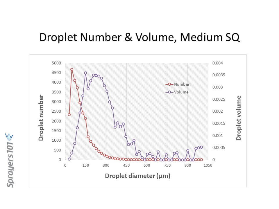
Droplet size distribution by number and volume from a Medium spray. Note the majority of the droplets are small, but the majority of the volume (dose) is in somewhat larger droplets. 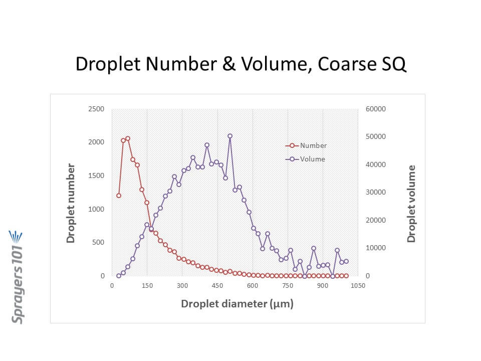
Droplet size distribution by number and volume from a Coarse spray. Like in the Medium spray, the majority of the droplets are small although there is fewer of them. The majority of the volume is in intermediate sized droplets. 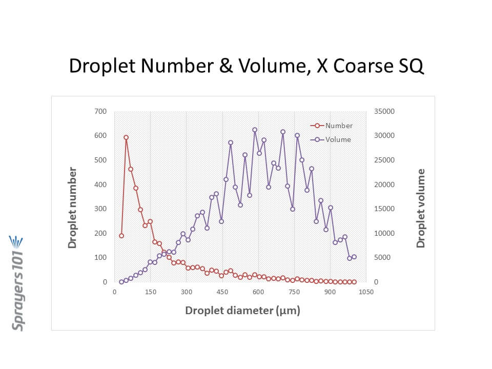
Droplet size distribution by number and volume from a Very Coarse spray. While the majority of the droplets are small as in the finer sprays, their overall number is sharply reduced from the finer sprays. The volume is now in the largest droplet sizes. Let’s focus on hydraulic nozzles, by far the most common in agriculture.
Spray Pressure
Spray pressure is a useful tool for controlling droplet size from any hydraulic nozzle. Need a finer spray? Add pressure. It is also the basis for the age-old recommendation that lower pressures are a good tool for reducing drift.
We impose practical limits on the upper and lower range of recommended pressures based on several other factors, chief among them the spray pattern.
Spray patterns of a certain width, or angle, are required for proper pattern overlap. The convention is to space hydraulic nozzles at 15 or 20 inch intervals along a boom, and operate them at about 20” above the target. Boom height values will depend on the fan angle of the nozzle and the degree of overlap required. For low-drift flat fan tips, a minimum 100% overlap is best. With 100% overlap, the spray pattern width at target height is twice the nozzle spacing. With this approach, at any point under the boom, the target receives droplets from the closest two nozzle patterns.
Pattern angles are published by manufacturers, but in practice, angles often differ from those values and can vary with spray formulation. Importantly, they tend to become narrower at lower pressures. The exact pressure at which this happens depends on the tip design, but experience shows that pressures below 20 psi for conventional nozzles, and 30 to 40 psi for low-drift nozzles, result in poor (too narrow) patterns. Narrow patterns reduce overlap, resulting in poor distribution.
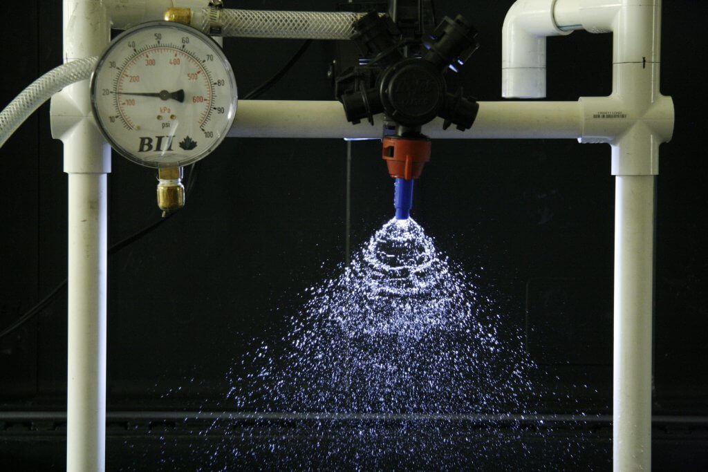
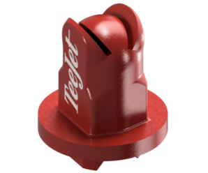
TeeJet AI11003 at 20 psi 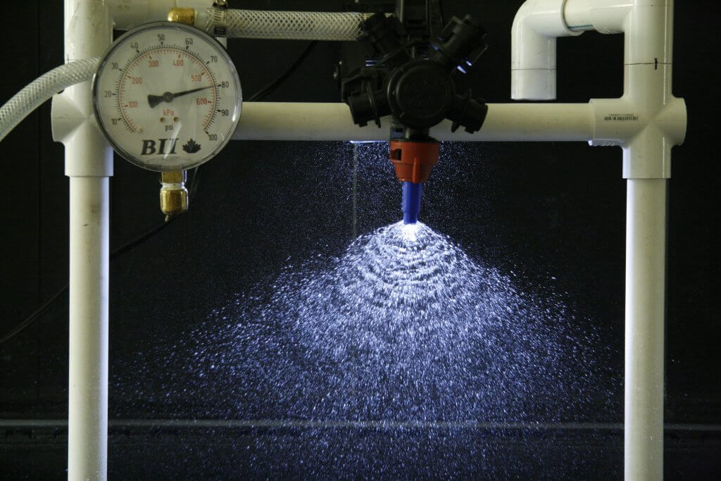
TeeJet AI 11003 at 80 psi We might also limit pressures at the upper end, based on drift potential. Most conventional flat fan nozzles, for example, drift excessively at pressures above 60 psi or so, hence that limit.
Low Drift Nozzles
Low drift nozzles were quickly adopted by applicators due to their ability to reduce drift and thereby widen the window of safe spray application. They work by using a two-stage design (often called “pre-orifice”) to reduce the internal operating pressure of the tip. The pre-orifice, the original liquid inlet, is round and sized for the nominal flow of the tip. The exit orifice is eliptical in shape and has a larger flow capacity than the pre-orifice, by about 1.2-fold to 2.5-fold. The larger exit creates an internal pressure drop, so the pattern formation produces larger droplets as though the operating pressure had been reduced. Most modern low-drift tips also introduce air into the nozzle via a built-in venturi. This further suppresses the formation of driftable droplets and introduces air into the interior of the nozzle, adding some pressure back to the system.. The Albuz AVI nozzle schematic below explains the venturi design.
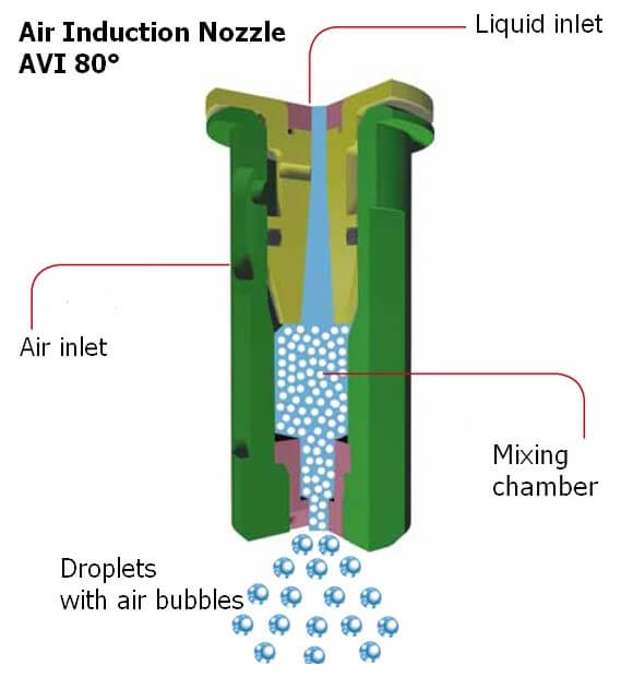
Cross-section of the Albuz AVI venturi nozzle. The tapered channel inside the nozzle is a venturi, which draws air into the nozzle via integrated ports. When low-drift nozzles are operated beside conventional nozzles at the same pressure, low-drift nozzles produce much fewer driftable fines, and also more larger droplets.
But while the two-stage design is useful for managing drift, it also conceals the actual operating pressure of the exit orifice in these tips. The exit orifice is important – it is the part of the nozzle that does the atomizing and that forms the pattern.
Let’s illustrate the pressure inside a low-drift tip by operating an air-induced low-drift nozzle at 60 psi. This nozzle has a pre-orifice size of 03 (0.3 US gpm at 40 psi, blue) and an exit orifice size of 06 (0.6 US gpm at 40 psi, grey). The operator sees 60 psi on the gauge. What is the exit orifice pressure?
The exit tip has twice the flow-rate of the pre-orifice, and therefore operates at one quarter the pressure, or 15 psi. Recall the square-root relationship between flow rate and pressure.
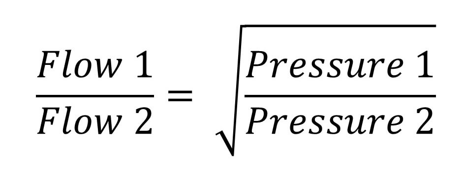
The relationship between spray pressure and flow rate. Doubling the flow rate requires a quadrupling of pressure That’s not the whole story. The internal venturi is drawing additional air into the nozzle chamber, and depending on the operating pressure, this could be from 5 to 15 psi. The amount added depends on the specific nozzle, its flow rate, and its pressure. Let’s add 10 psi in this case. The exit tip is actually at 25 psi.
Now let’s assume the pressure gauge reads 40 psi, and that the venturi generates 5 psi additional pressure. The actual exit orifice pressure is now only 15 psi. This is at the lower limit at which a spray is atomized, and at which a good pattern can form.
Our general recommendation with venturi-style low-drift tips has been to avoid pressures below 30 or 40 psi for that reason. We’re trying to prevent the spray becoming too coarse for adequate coverage, and also to prevent the spray pattern from collapsing.
The upside of this design is that the same principle allows for much higher-pressure operation without creating excessive drift. These types of nozzle can, in fact, be operated at 70 to 90 psi without becoming very drift-prone because the pressure at which the spray liquid is atomized is likely only 30 or 40 psi (the actual exit pressure and drift potential will depend on the nozzle and the formulation).
Speed Range
A low-drift nozzle with a pressure operating range from 30 to 90 psi (i.e., 3-fold) would have a flow rate range of 1.73 (i.e., the square root of 3 due to the square root relationship of flow rate and spray pressure). This means that the fastest travel speed (at 90 psi) would be 1.73 times the slowest travel speed (at 30 psi).
A conventional nozzle operating between 20 and 60 psi would have the same travel speed range. So why don’t we just do that? The main reason is that the two-stage design lowers the overall amount of drift substantially, something a conventional nozzle can’t achieve even at very low pressures.
A second reason is that even at high pressures, a two-stage design will likely drift less than an conventional nozzle. This is still the case if the conventional nozzle is operating at low pressures. Any spray quality chart comparing spray qualities of conventional and low-drift tips will demonstrate that.
Pulse Width Modulation
PWM uses a solenoid to intermittently shut off nozzle flow, between 10 and 100 times per second (Hz) depending on the manufacturer. This has implications for nozzle design because the nozzle must not leak liquid during the brief off-cycle. If it does, the small amount of liquid leaving the nozzle will not only not atomize properly, it will also cause a pressure drop within the nozzle which must be replenished with the next on-pulse. This will mean the on-pulse will operate at a lower initial pressure, affecting pattern development and atomization. For this reason, venturi-style low-drift nozzles have not been recommended with PWM. The venturi provides an alternate exit for air or liquid, compromising nozzle performance.
And yet, some venturi style nozzles do, in fact, produce acceptable patterns with PWM according to the nozzle manufacturers. This goes to show that nozzle design can continue to evolve to provide the best in drift reduction technology with PWM. Design for PWM suitability should be at the top of nozzle manufacturers’ agendas.
Nozzle design continues to evolve. But in the foreseeable future, spray pressure will continue to control pattern width and droplet size. That’s why understanding the pressure limits of any specific nozzle type, and maintaining pressure within those limits, is so important in any spray operation.
Steps to Calibrate your Field Sprayer
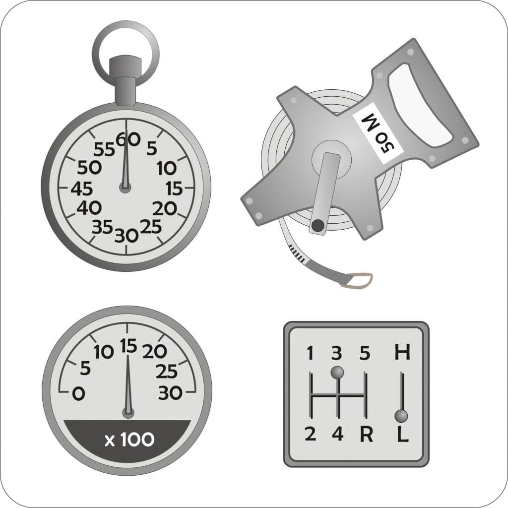
Calibrating a boom sprayer is not as difficult as it sounds. There are several ways to calibrate a sprayer. Regardless of which method you choose, it usually doesn’t take more than 30 minutes, and only three things are needed:
- a timer (or watch or smart phones) showing seconds,
- a measuring tape, and
- a jar graduated in ounces.
Here, I will describe perhaps the easiest of all the methods to calibrate a field sprayer.
Now is the time to get the field sprayer out of the shed and get it ready for the season. Check all the components of the sprayer to make sure they are in working order. Next step in preparations for the season is to calibrate the sprayer. The only way you can achieve maximum accuracy from a sprayer is by calibrating it once before the spraying season starts, and re-calibrating it frequently throughout the spraying season. While applying too little pesticide may result in ineffective pest control, too much pesticide wastes money, may damage the crop and increases the potential risk of contaminating ground water and environment. The primary goal with calibration is to determine the actual rate of application in gallons per acre, then to make adjustments if the difference between the actual rate and the intended rate is greater or less than 5% of the intended rate. This is a recommended guideline by USEPA and USDA.
Before starting calibration, make sure you have a good set of nozzles on the sprayer. Nozzles wear through extended use causing over application, or some nozzles may be plugged. Clean and check the output of all the nozzles for a given length of time at a given spray pressure (usually 1 minute and 40 psi). Compare output from each nozzle’s output with the expected output shown in the nozzle catalog for that nozzle at the same pressure. Replace the nozzles showing an output error of more than 10% of the output of the new nozzle. Once you do this, now you are ready to calibrate your sprayer.
- Fill the sprayer tank (at least half full) with water.
- Run the sprayer, inspect it for leaks, and make sure all vital parts function properly.
- Measure the distance in inches between the nozzles.
- Measure an appropriate travel distance in the field based on this nozzle spacing. The appropriate distances for different nozzle spacing is as follows: 408 ft for a 10-inch spacing, 272 ft for a 15-inch spacing, 204 ft for 20-inch spacing, 136 feet for a 30-inch spacing, and 102 feet for a 40-inch spacing.
- Drive through the measured distance in the field at your normal spraying speed, and record the travel time in seconds. Repeat this procedure and average the two measurements.
- With the sprayer parked, run the sprayer at the same pressure level and catch the output from each nozzle in a measuring jar for the travel time required in step 5 above.
- Calculate the average nozzle output by adding the individual outputs and then dividing by the number of nozzles tested. The final average nozzle output in ounces you get is equal to the application rate in gallons per acre. For example, if you catch 15 ounces from a set of nozzles, the actual application rate of the sprayer is equal to 15 gallons per acre.
- Compare the actual application rate with the recommended or intended rate. If the actual rate is more than 5 percent higher or lower than the recommended or intended rate, you must make adjustments in either the spray pressure or the travel speed or in both. For example, to increase the flow rate you will need to either slow down, or increase the spray pressure. The opposite is true when you need to reduce application rate. As you make these changes stay within proper and safe operating condition of the sprayer. Remember increased pressure will result in increasing the number of small, drift-prone droplets.
- Repeat steps 5-8 above until the recommended application error of +5% or less is achieved.