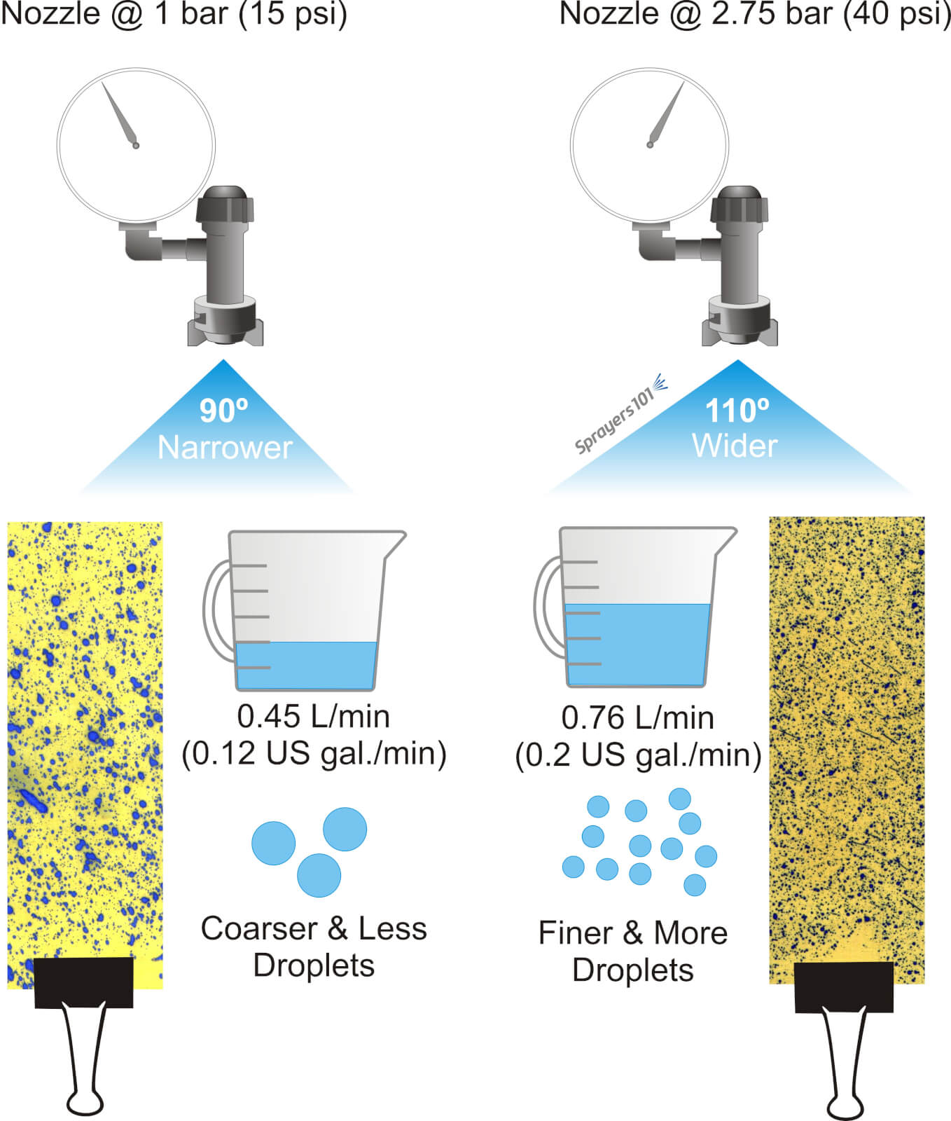
Pressure is integral to nozzle performance. Reducing hydraulic pressure reduces nozzle flow rate, increases median droplet size, and typically reduces spray fan angle. Increasing pressure increases nozzle flow rate, reduces median droplet size and typically increases spray fan angle.
You can watch this Exploding Sprayer Myths video to learn how pressure, boom height and nozzle spacing interact. In extreme cases, too low a pressure can collapse the fan angle enough to reduce overlap and compromise coverage, as explained in the video at the end of this article.
Using a flat fan nozzle as an example, a lower pressure increases the median droplet diameter, reduces the droplet count, reduces the nozzle flow rate and typically reduces the spray angle. Alternately, a higher pressure decreases the median droplet diameter, increases the droplet count, increases the nozzle flow rate and typically increases the spray angle.
Always plan to operate a nozzle in the middle of its recommended range so it can handle small changes in pressure during spraying (such as from a rate controller, or when changing PTO speeds on hilly terrain). Don’t operate an air induction nozzle below 2 bar (30 psi), even if it’s rated lower in the manufacturer’s nozzle table. Most AI nozzles perform best at >4 bar (60 psi).
Pressure can be used on-the-fly to make minor changes to flow rate while spraying. This is how rate-controllers work to compensate for changes in ground speed and maintain a constant overall rate per planted area.
However, pressure should not be used to make significant changes to flow rate. It takes a 4x change in pressure for a 2x change in flow rate, so it’s inefficient. Operating pressures at the upper or lower limit of a nozzle’s range can have undesirable impacts on nozzle wear, median droplet size and swath uniformity.
For a more in-depth discussion of the relationship between spray pressure and nozzle performance, and how rate controllers work, check out this article.
Note: It is far better to simply switch nozzles when a significant change in flow rate is required.
In 2015, we ran demonstrations at Ontario’s Southwest Agriculture Crop Diagnostic Days. The 20 minute sessions were designed to explain:
Although manufacturers of air induction nozzles often rate their performance as low as 15 psi, such a low pressure collapses the spray pattern and the resulting gaps reduce coverage. Additionally, the spray quality at such low pressures is coarser than at higher pressures, reducing the number of droplets available. This further reduces coverage potential.
This video covers the key speaking points from that demonstration.
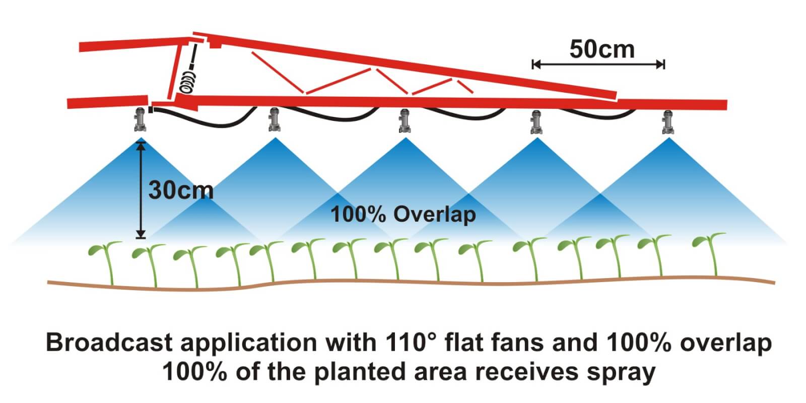
Where crops are planted in rows, growers can save on chemical costs and reduce potentially wasted spray by performing banded applications. A banded application is treating parallel bands (Figure one), unlike a broadcast application where the entire area is treated (Figure two). This means only a portion of the field or orchard/vineyard floor receives spray, so the total amount of product applied per hectare (or per acre) should be less for banded than for broadcast.
Figure 1Figure 2
Banded applications are used in many situations, including:
Applying herbicides right over a crop during planting, both for pre-emergent or post-emergent crops.
Applying insecticides/fungicides by “directed spraying” using drop hoses or row kits; the latter is pictured in Figure three.
Carefully spraying herbicide between the rows to control weeds in the alleys of an established crop (Figure one).
Applying herbicide under fruit trees or grape vines to control weeds (Figure four).
Figure 3Figure 4
It’s easy to make mistakes when calculating product rates for banded applications and these can be costly errors: too little means poor control and too much means wasted product and possible crop injury. This article describes how to calculate sprayer output and product rate for common banded applications.
Step One: Determine broadcast volume
Pesticide labels typically list broadcast product rates (e.g. amount of formulated product per hectare or acre). In this example, let’s say the label recommends a broadcast product rate of 500 ml of formulated herbicide applied using 100 litres of spray mix per hectare (i.e. added to 99.5 L water).
Step Two: Establish sprayer settings
Select a travel speed that is safe, gives decent efficiency and doesn’t compromise coverage. For this example, we’ll say the sprayer moving is at 8.0 km/h.
Select a band width that completely covers the target row and some of the adjacent area where control is desired. Band width should be measured along the ground for soil-applied products or along the top of plants for post-emergence products. We’ll use Figure one for our settings: bands are 50 cm wide on 100 cm centres. We’ll say that a single nozzle swath can treat the band, and that we’re spraying 2 hectares of planted area.
Step Three: Calculate the banded sprayer output
We can calculate how much of the planted area actually receives spray using this formula:
[band width (cm) ÷ row width (cm)] x total planted area (ha) = actual sprayed area (ha) [50 cm ÷ 100 cm] x 2 ha = 1 ha
For completeness, here’s the US formula: [band width (in) ÷ row width (in)] x total planted area (ac) = actual sprayed area (ac)
From this we now know that we should be able to go twice as far on a tank spraying a banded application as we would a broadcast, because we’re only spraying half the planted area.
Step four: Calculate the nozzle output
Use the following formula to convert the broadcast output into the banded output:
[broadcast output (L/ha) x travel speed (km/h) x (swath width (cm) ÷ number of nozzles per swath)] ÷ 60,000 = nozzle output (L/min) [100 L/ha x 8 km/h x (50 ÷ 1)] ÷ 60,000 = 0.67 L/min
For completeness, here’s the US formula: [broadcast output (gal/ac) x travel speed (mph) x (swath width (in) ÷ number of nozzles per swath)] ÷ 5,940 = nozzle output (gal/min)
If multiple nozzles were contributing to the swath, such as in figure three or figure four, this formula will account for it. You still mix the labelled product rate at a ratio of 500 ml of herbicide to 99.5 L water, but as we determined in step three, we should be able to spray twice the planted area using a banded application as we would a broadcast application.
Warning! Watch your units. You may be familiar with other formulae for calculating your output. Do not mix and match formulae or parts of formulae. For example, here is another Metric option for determining L/min. It employs different units so it requires a different constant:
[broadcast output (L/ha) x travel speed (m/min) x (swath width (m)) ÷ number of nozzles per swath)] ÷ 10,000 (m2/ha) = nozzle output (L/min)
Step Five: Use the nozzle catalogue to find the right nozzle
Using a nozzle manufacturer’s catalogue, select a nozzle that gives the desired spray quality (usually coarser for herbicides) and will produce the 50 cm swath we’re looking for (which can be adjusted a little using boom height). Always choose to operate a nozzle in the middle of its pressure range.
Step Six: Calibrate the sprayer (i.e. double-check)
Follow your typical calibration process and make minor adjustments until the nozzle discharge per minute results in the desired banded output. A rate controller will handle this on larger sprayers, but if you don’t have one you can make small adjustments to speed and pressure until the desired output is achieved. Ideally, if your math was right, these changes won’t be needed.
When performed correctly, banded applications are a great way to focus your efforts on the target, saving time and money.
Here are a few additional resources if you’d like to learn more, or work with a few online calculators:
Sprayer math is important. It ensures the operator applies the correct product rate and has enough to complete the job. But, it assumes the airblast sprayer is behaving as expected… and it often doesn’t. After confirming the airblast travel speed, use one of the following methods to assess sprayer output. There are pros and cons to each.
The area method
Operators that claim the sprayer empties in the same place every time assume everything’s alright. They are performing a variation on the area method.
Essentially, you fill the sprayer with enough water to spray one hectare (or acre) and then spray that area. If the tank empties where expected, you know your output rate (i.e. volume / area). But, there are a few problems with this method:
Most operators don’t have an accurate test area marked off, and even when they think they know the area, measurements prove otherwise. They’re always amazed when this happens.
The area method has poor resolution. It reveals the total output but does not assess individual nozzles. For example, partially-blocked nozzles and worn nozzles average out (we’ve seen it). Rate controllers provide whatever pressure is required to match the desired output, masking individual nozzle problems.
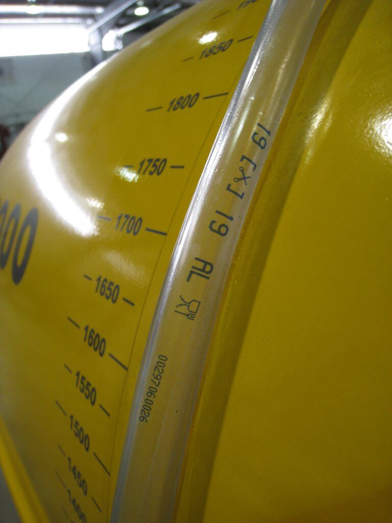
The dip stick method
Another method is to fill the sprayer to a known volume using a flow meter, while observing a sight level or a graduated dip stick. Then, while parked, the operator sprays for a given amount of time and determines the difference in the volume remaining in the tank.
This method can be defeated if volume is misread. It’s an easy error to make if the sprayer is parked on a grade, or the dipstick shifts in a tank with a rounded bottom. And, of course, it also masks individual nozzle problems.
Sight levels can be misleading when the sprayer is parked on a grade. They are often opaque and hard to read.
The timed output method
The preferred method is to measure the output of each nozzle individually. We performed a review on several timed output methods here. It can be messy and time consuming, but it’s accurate. Appropriate personal protective equipment is required to perform the timed output method – expect to get wet.
1. Fill the rinsed sprayer half-full with clean water and park it on a level surface.
2. With the fan(s) off, bring the sprayer up to operating pressure. Start spraying with all nozzles open (closing any will change the pressure).
3. You will need 1 meter (3 feet) of 2.5 cm (1″) diameter braided hose (have a second, longer hose to reach the top of a tower sprayer). It should be stiff enough that you can slip it over a nozzle body while holding the other end. Use it to guide flow into a collection vessel, held with your other hand. The hose not only reaches the top nozzle on towers, but it lets foam dissipate before it gets to the vessel.
4. When the flow from the hose is steady, direct it into the collection vessel for 30 seconds (a partner with a stopwatch is very helpful). It is preferable to collect for a minute because it improves the accuracy.
5. Determine and record the nozzle output per minute. Graduations on plastic collection vessels are unreliable. It’s preferable to weigh the output on a cheap, digital kitchen scale. One milliliter of clean water weighs one gram. Don’t forget to subtract the weight of the vessel (this is called taring) and double the output if you only collected for 30 seconds.
Interpreting the results
Once you have recorded all the outputs, you will have to convert the output to U.S. gallons or liters per minute, depending on units in the nozzle manufacturer’s catalogue (see common conversions below).
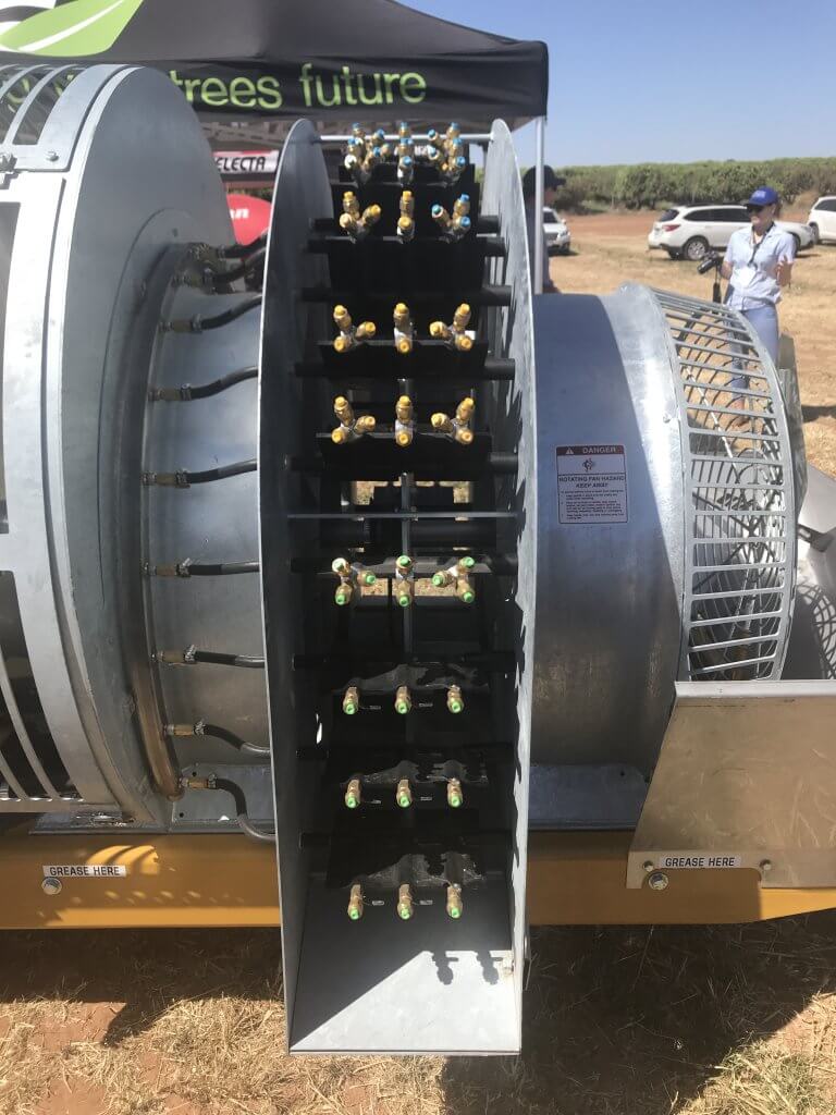
Replace any nozzles that are 10% (or preferably 5%) more or less than the rated output. This not only indicates a rate problem, but likely a problem with droplet size as well. If enough nozzles are worn, consider replacing all of them. Nozzles should go on as a set, and come off as a set (unless replacing a broken tip, of course). This can be an expensive proposition for large airblast sprayers, but it is part of operational costs.
Don’t assume new nozzles are accurate. We’ve found +/- 5% flow variation right off the shelf. Keep your receipts.
Testing and replacing nozzles is an important part of sprayer operation, no matter how many there are. This Air-O-Fan is nozzled for Australian almonds.
Helpful conversions
Anyone that has tried the timed output method in Canada knows the pain of our Metric-esque (Mocktric?) units. We’re an odd hybrid because our label rates are in metric, but our nozzles and many of our sprayers are US Imperial. You can find a complete collection of conversion tables here, but the most common calculations are reproduced below:
If collecting in ounces, converting to U.S. Gallons per minute:
If collecting in millilitres or grams converting to U.S. Gallons per minute:
If collecting in ounces, converting to litres per minute:
If collecting in millilitres or grams converting to litres per minute:
If collecting in ounces, converting to Imperial gallons per minute:
If collecting in millilitres or grams converting to Imperial gallons per minute:
A more sophisticated option
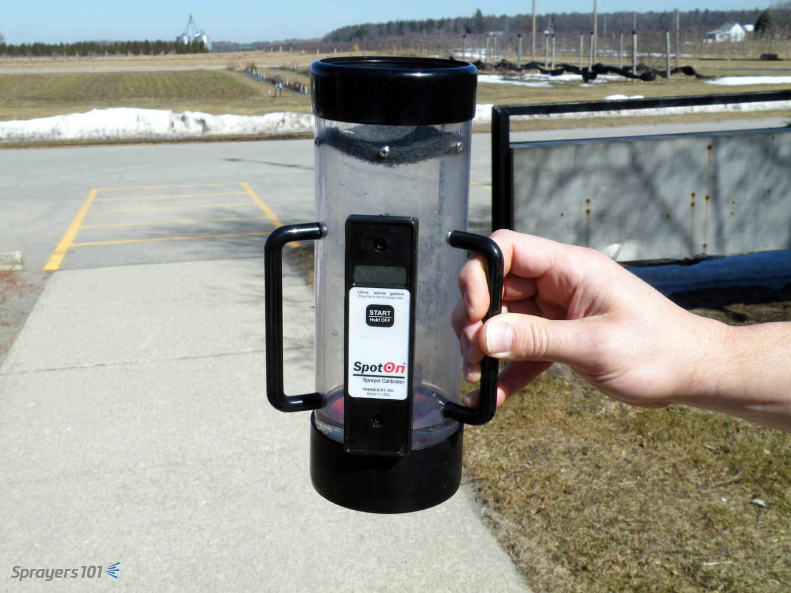
The timed output method is slow and requires math. You can avoid both problems by using electronic calibration vessels like the Innoquest SpotOn SC-4. We’ve tested both, and they are as accurate as weighing the output – but much faster.
They can, however, be fooled by foam. We’ve had good results using a length of braided hose to direct the flow and dissipate most of the foam. Typically, foaming means the sprayer wasn’t rinsed enough.
The SpotOn calibration vessel is easier, faster and more accurate than the classic pitcher-and-stopwatch approach to timed output tests. The SC-4 (pictured) is for airblast and SC-1 is for field sprayers.
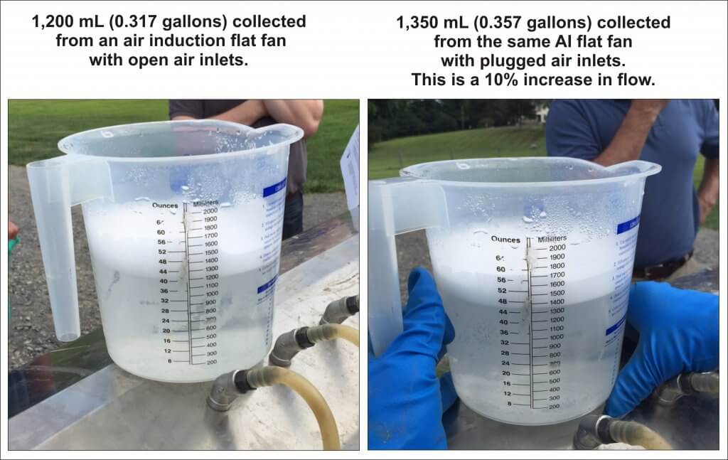
Another approach is to hose-clamp multiple hoses over nozzle bodies and spray all at once. This is tricky and takes time. Plus, if you suffocate the nozzle’s exit orifice (creating back pressure) or block the air inlets on AI nozzles, you will get a false reading.
Be careful not to plug air inlets on air induction nozzles – you may get a false reading.
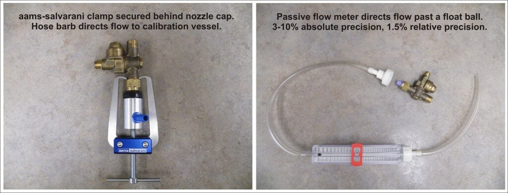
We prefer nozzle clamps over hose clamps (see the AAMS-Salvarani nozzle clamp pictured below). There are pincers designed to latch behind the nut of the nozzle body, but compatibility can sometimes be an issue (e.g. with Turbomist sprayers).
Passive flow meters (also pictured below) remove the need for a collection vessel, but they’re a better fit for field sprayers since they have to be held in place manually. They are difficult to source in North America because their accuracy is questionable, but they are fine for comparing relative flow from tip to tip.
Nozzle clamp or flow meter, avoid suffocating the nozzle exit orifice or AI nozzle air inlets.
Left: Nozzle body hose clamp. Right: Passive flow meter.
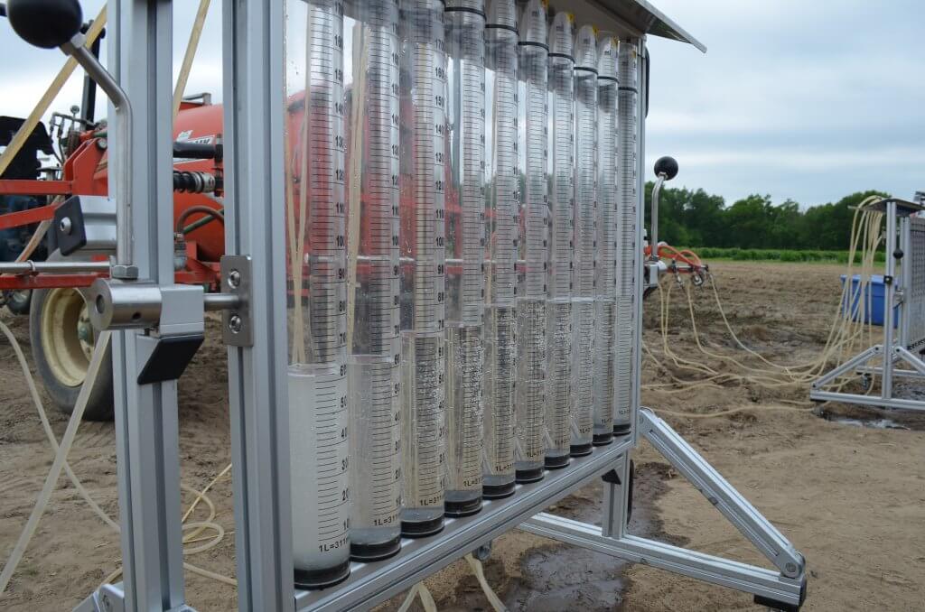
Some grower groups, or professional consultants, spring for very sophisticated and accurate units, such as AAMS-Salvarani flow measurement system pictured below.
AAMS-Salvarani flow measurement system. We used these on a pumpkin sprayer in New Hampshire, but they work with airblast too.
No matter your preferred method, take the time to confirm your sprayer output at the beginning of the season and whenever you make repairs or significant changes to your sprayer.
When warm air is cooled, it loses some of its moisture-holding capabilities. This change often occurs at night, when plants (and other objects) cool. Once the temperature of the surface of the leaves, for example, drops below the dewpoint, it causes water to condense, forming the shiny dew that causes so many to question early morning spray applications.
The question is often: will the spray run off the plant or will it get so diluted that it doesn’t work anymore?
In a dew chamber, work has shown that large spray droplets are more likely to run off a plant saturated with dew than their smaller counterparts. However, similar work showed that spray efficacy was not altered by droplet size.
Wolf discusses this work and the potential answer to the seemingly conflicting findings. Wolf also explains how grassy weeds compare to broadleaves, the role of surfactants, and what to consider when making the decision to spray through dew or not.
Excepting air shear and centrifugal style nozzles, most airblast sprayers employ nozzle bodies designed to except hydraulic nozzles distributed evenly along the booms. Nozzle caps compress the nozzle against the body to force the spray mix through the nozzle orifice. Nozzle bodies are not all created equal.
Double Outlet Roll-Over Nozzle Bodies
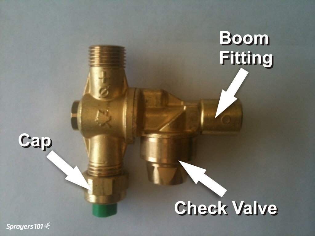
Double outlet roll-over bodies (pictured below) allow the operator to quickly switch between two nozzles mounted in each position. This is convenient when alternating from dilute to concentrated applications, or changing the spray distribution from block to block.
A typical brass roll-over style nozzle body with cap and check valve.
The roll-over feature can act as a shut-off and facilitate fine-tuning the orientation +/- 15° from centre. When roll-overs are new there is an audible ‘click’ when they reach 15° to alert the operator that turning them any further will interfere with flow. This feature fails as bodies wear.
Single Nozzle Bodies
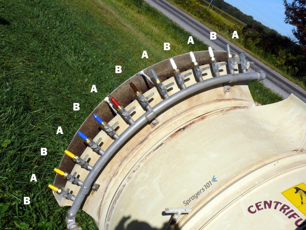
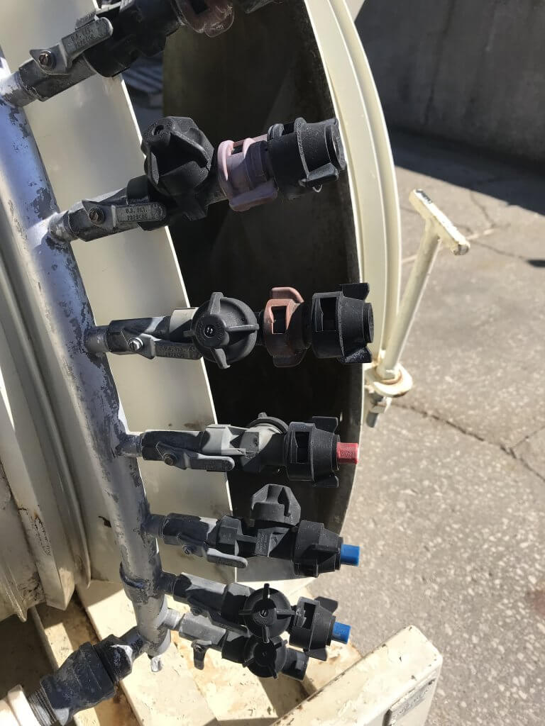
Some sprayers employ single nozzle bodies featuring screw or lever-style quarter-turn shut-offs. Some sprayers, like the Turbomist featured below, double the density of the bodies along the boom, arranged in an alternating A-B pattern. The operator shuts off each alternate nozzle, perhaps using the A’s for dilute and the B’s for concentrate applications. The density gives the operator the ability to “double up” in positions along the boom if more spray is required.
Some sprayers do not use double outlet roll-over nozzle bodies. Instead, they double the density of single bodies along the booms for use in an alternating A-B pattern.
Still others may affix the nozzle bodies to the deflectors (like the Air-O-Fan below), permitting the operator to orient the air and nozzles at the same time.
The Air-O-Fan offers double-density by affixing two single nozzle bodies to each air deflector. The operator aims air and nozzles simultaneously and can select flow combinations using quarter-turn shut-offs.
Check Valves
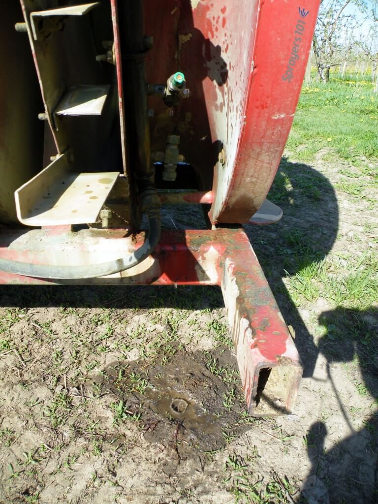
In my opinion, it should be mandatory for nozzle bodies (or at least booms) to have diaphragm check valves. When pressure drops below ~15 psi the valves shut to prevent the boom from draining (see image below).
An older FMC with nozzles bodies that do not have check valves. Once the pressure is off, the booms drain through the lowest nozzle. This is a waste of pesticide and unnecessary environmental contamination.
Booms don’t just drain in the yard. Operators shut off the outside boom when turning at the end of a row. Without check-valves, the boom drains through the bottom nozzle, wasting pesticide and causing repeated and unnecessary point-source contamination. Further, it takes a moment for the boom to refill, meaning the top nozzles may not be spraying at the beginning of each row.
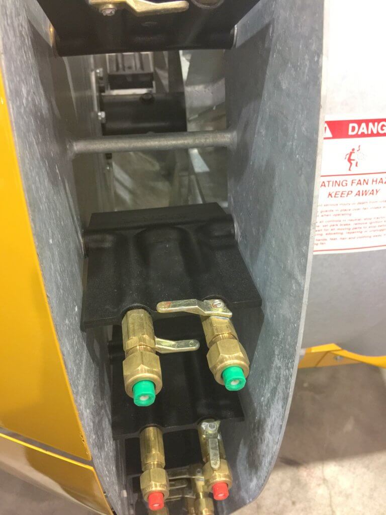
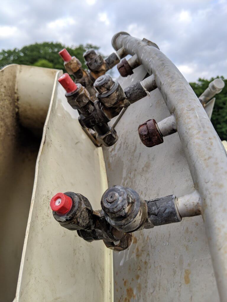
You may be tempted to purchase mesh nozzle strainers with built-in ball valves. They can work as an alternative to integrated nozzle body check valves, but they plug and fail with irritating regularity. The image below shows a creative method for installing check-valves on single nozzle bodies. The nozzles protrude and the check valve seems too close to the shut-off, but reputedly this works.
An example of retrofitting diaphragm check valves on single nozzle bodies.
Thread Types
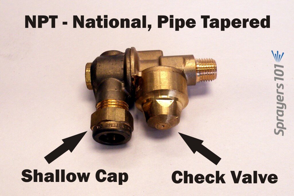
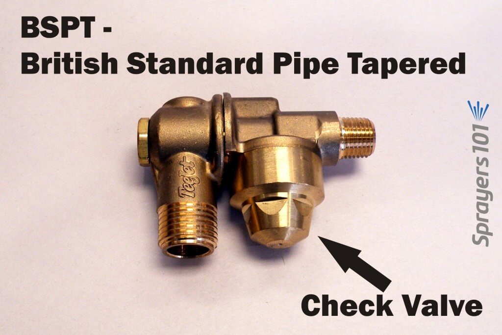
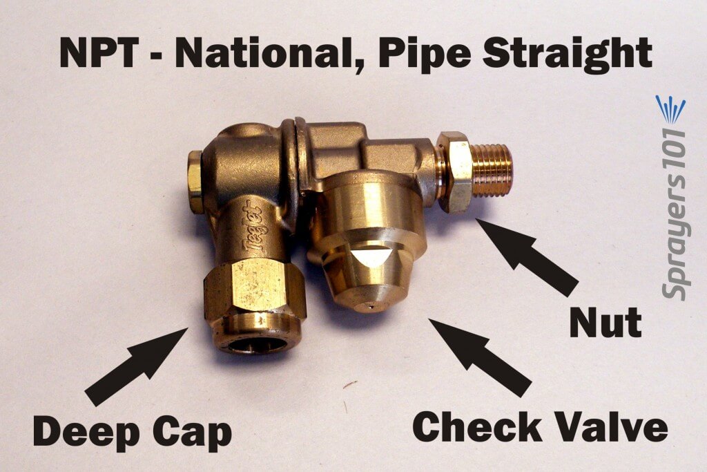
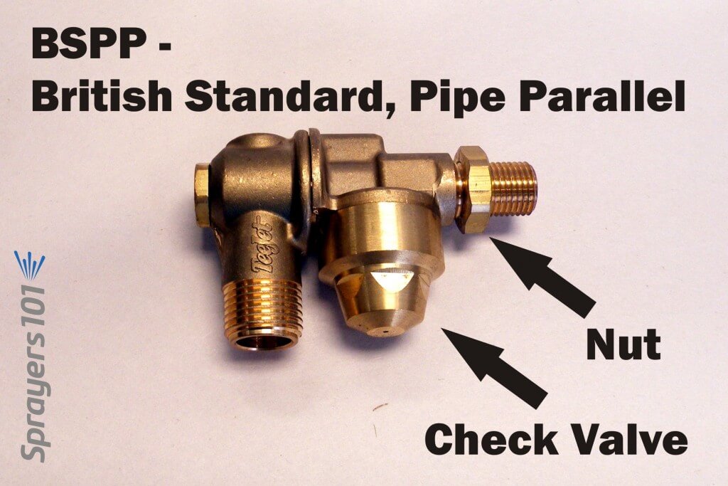
In North America, you will encounter four inlet thread types: NPT, BSPT, NPS and BSPP.
National, Pipe Tapered (NPT) single-sided, brass roll-over nozzle body with check valve. Note the shallow cap pictured here.British Standard, Pipe Tapered (BSPT) single-sided, brass roll-over nozzle body with a check valve.National, Pipe Straight (NPS) single-sided, brass roll-over nozzle body with check valve. Note the deep cap pictured here.British Standard, Pipe Parallel (BSPP) single-sided, brass roll-over nozzle body with a check valve.
The inlet thread sizes available are 1/4” female, 1/4” male and 3/8” male. 1/4” female is not available on the NPS or BSPP inlet thread types. If you are considering installing new roll-over bodies, know your boom’s thread type. The retrofitted Turbomist below, for example, required bodies with female fittings.
A retrofitted Turbomist with check valves and female double outlet roll-over bodies.
Molded Nozzles
Another reason for installing new bodies is to convert from disc & core combination nozzles to single-piece, molded nozzles. They may not fit existing nozzle bodies. Check the diameter of the body outlet (where the nozzle rests) and the outlet cap (which compresses the nozzle against the body outlet). Your sprayer may currently use an unusual-diameter nozzle, like older FMC disc & whirls or European large-diameter pink ceramic disc & cores. Today’s ISO molded nozzles won’t fit in those bodies, so you’ll need to replace them.
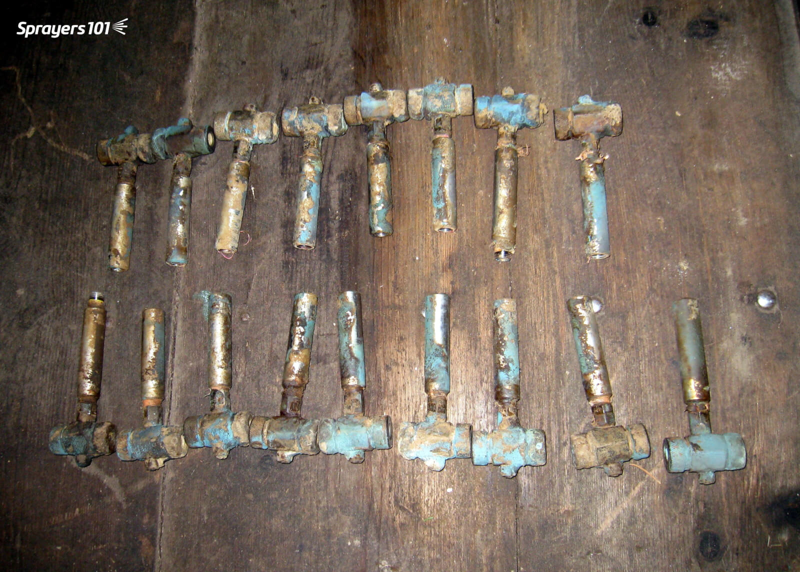
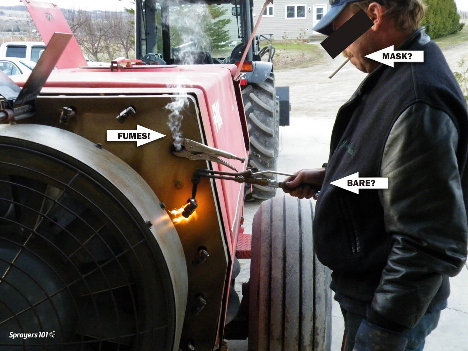
Old roll-over bodies without check-valves. These were removed to make way for better bodies.Older nozzle bodies can seize in the boom, requiring novel approaches to removing them. In this case, the mechanic is heating the fittings using “the blue wrench” to loosen them. If you do this, do not do what this mechanic did. Operate in an open space using gloves and a respirator. Years of residue build-up should be anticipated and respected.
Be aware: that unlike disc and core, molded nozzles protrude and may hit the edge of the sprayer duct when rolled over, preventing them from turning freely
Nozzle Body Caps
Nozzle bodies DO NOT come with the nozzle caps; they are specific to the nozzle type and must be ordered separately. This was an unpleasant surprise the first time I ordered a set of bodies.
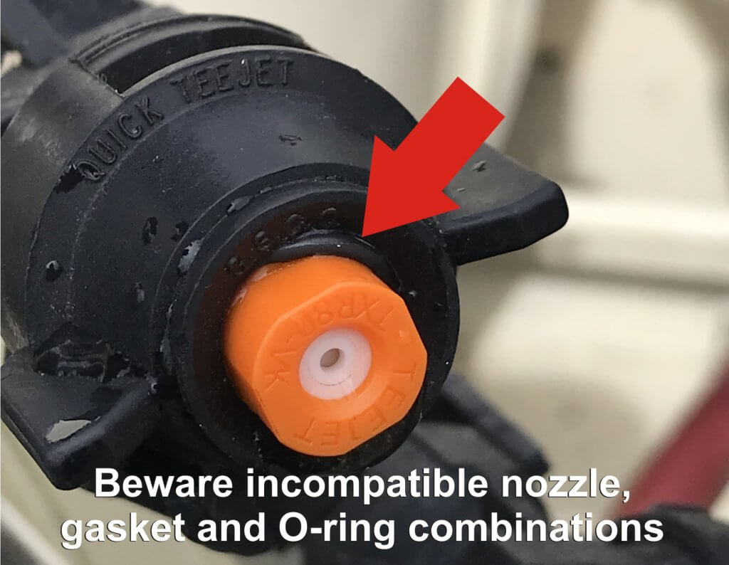
The standard caps are threaded brass hex nut-style but there are also nylon wing-style caps that don’t require a wrench. Beware converting to quarter-turn systems for airblast sprayers. It can work, but nozzles may require additional gaskets and O-rings… and even then are known to leak if the cap diameter is too large (see below):
Airblast pressure often exceeds 100 psi and can force the O-ring off the molded nozzle and cause leaks.
Be aware: North American nozzle caps might not fit imported European bodies, and European nozzles might not fit North American cap diameters. The LipCo sprayer is one such example.
Regarding the cap depths, sprayer operators must consider the how much “stuff” is between the nozzle body and cap. Gaskets, spacers, O-rings and strainers take up room that may warrant a deeper cap. Perhaps most critical is the nozzle itself. For example, brass disc-core are quite thin, but ceramic are much thicker. They require different cap depths.
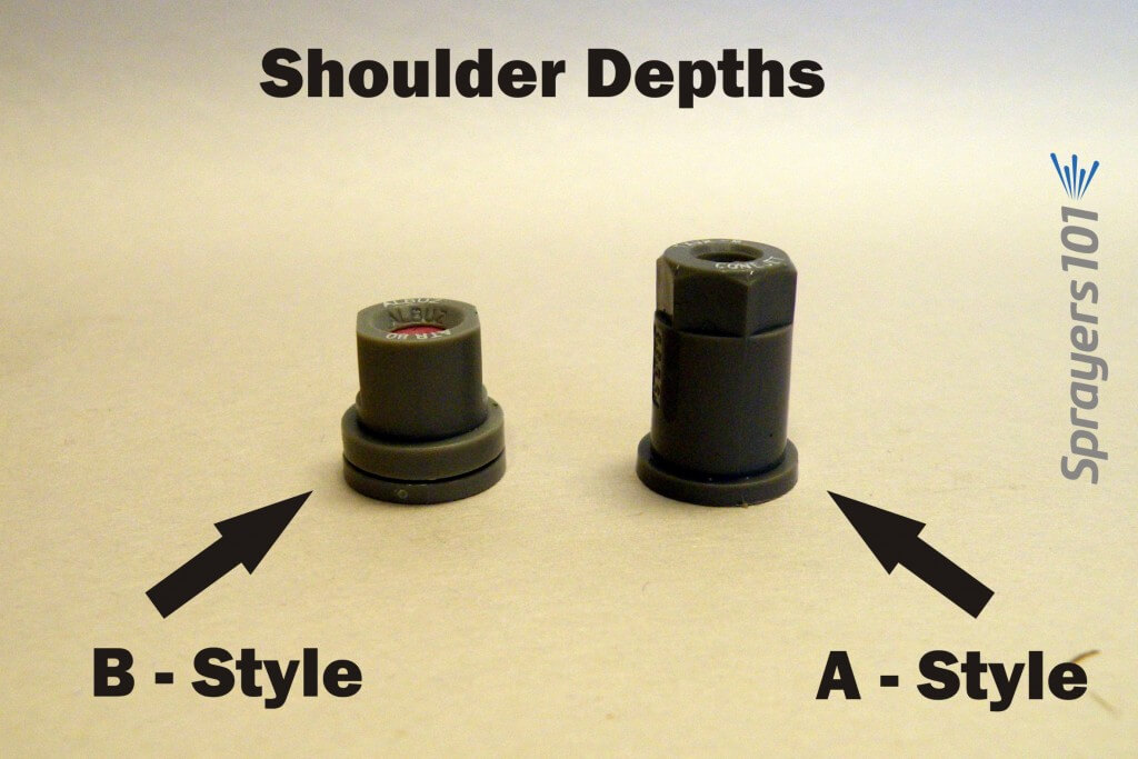
TeeJet’s molded cone nozzles come with an ‘A’ (Thinner) or ‘B’ (Thicker) shoulder. The shoulder is the lip around the nozzle base that is compressed against the nozzle body outlet. The B-shoulder is the ISO standard, and is preferred (see below). Shallow caps may not thread onto a nozzle body using a nozzle with a B-shoulder. Deep caps may bottom-out before compressing a nozzle with an A-shoulder, creating leaks. Be sure to note in the nozzle catalog which caps are recommended for the nozzle.
Molded cone nozzles come in the thin shoulder (A-style) or thick shoulder (B-style) varieties. The B-style is the ISO standard and is preferred.
Nozzle Strainers (aka Filters)
Before we wrap up, here’s one more look-out. As mentioned, the nozzle strainer shoulder takes up some room between nozzle body and cap. It turns out there can be another concern.
A hop grower contacted me. He had installed new nozzle bodies on his sprayer. He’d taken into account the shoulder depth and the cap depth. So why were his nozzles plugged? And why when he loosened the cap to finger-tight did they spray, but leak?
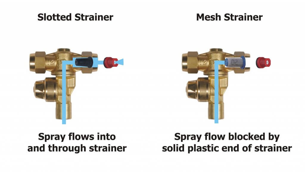
We tried gaskets, O-rings, different cap depths and new nozzles – but no change. That’s when we noticed one side of the roll-over body had a plastic slotted strainer and the other had newer mesh strainer. The mesh strainers were longer and terminated in a disk of solid plastic. When we swapped the two strainers, we had flow! We realized the longer mesh strainers were being compressed against the orifice in the nozzle body, acting like a cork in a wine bottle.
I prefer slotted over mesh because they are a bit more forgiving with dry formulations and hard water residue, but perhaps more critical is that they aren’t long enough to block the flow.
Be aware that some strainers may be long enough to block flow in the nozzle body.
Take Home Tips
If you are considering installing new nozzle bodies:
Confirm the male or female fitting and thread type of your boom
Ensure bodies have check valves
Ensure roll-overs and check valves clear any obstructions with nozzles in place
Know the nozzle type you intend to use, and ensure cap diameter is appropriate
Know whether you will use gaskets, o-rings, spacers and strainers, and confirm the cap depth will accommodate everything.
Be certain the strainer you choose isn’t so long that it interferes with flow.
Consider buying a single nozzle body to install as a trial before buying an entire set of replacements.