One of the pleasures of working in agricultural extension is when you’re able to help a grower solve a problem. This was one of those happy occasions. An orchardist purchased a Lipco multi-row recycling sprayer and wanted help evaluating their spray coverage.
We worked in 3.7 m (12 foot), mature, high-density Royal Gala trees. The sprayer was driving at 5.0 km/h (3.1 mph), operating at 11 bar (160 psi) using orange Albuz 80 degree air-induction flat fans. This resulted in about 350 L/ha (~37 gpa).
This grower wisely invested in the air-assist option, which produces a vertical plane of somewhat laminar air to entrain the spray and carry it into the centre of the target canopy. Whatever spray blows through the tree should impact the opposing shroud and get recycled back to the tank. All in all, how could you miss?
…we managed to.
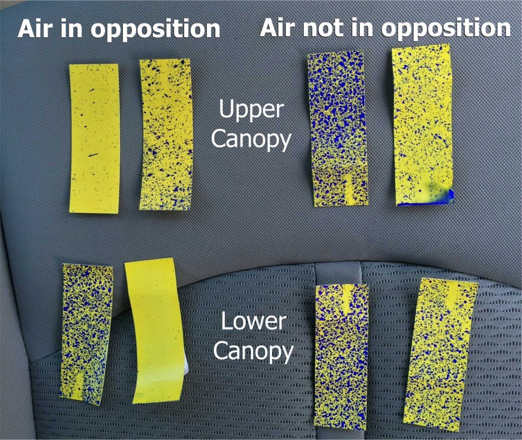
Water sensitive papers were placed back-to-back facing each alley (in other words, facing the spray booms). Despite our best efforts, each pass resulted in inconsistent coverage. Papers were replaced in the same location and orientation for each pass and no settings were changed. Nevertheless, sometimes a paper got spray and sometimes it didn’t. What was going on? It was as if the two air streams were interfering with one another – almost cancelling each other out.
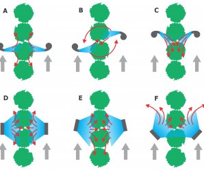
Air from tangential (cross-flow) fans oriented perpendicular to the canopy in direct opposition will cancel out. This reduces canopy penetration.
Where possible, do not position laminar air outlets in direct opposition. The convergence creates a high-pressure zone that reduces spray penetration. Some sprayers are designed to avoid this by staggering air outlets one ahead of the other. Laminar flows will deflect unpredictably around this pressurized area and carry droplets back out of the canopy. Unless the canopy is particularly narrow and sparse, turbulent air handling systems do not typically create this problem. In both cases, canopy penetration is improved when fans are staggered and/or are angled slightly forward or backward.
Grey arrows indicate direction of travel. The air outlets of wrap-around sprayers should be symmetrical when viewed from behind. A. Tangential fans in direct opposition: Poor coverage. B. Tangential fans angled forward/backward: Possible vortices and good coverage. C. Tangential fans angled backward: Good coverage, but if the angle is too steep, air will not penetrate the canopy. D. Straight-through axial fans in direct opposition: Good coverage in denser canopies. E. Straight-through axial fans angled slightly backward: Good coverage but limit the angle to prevent the trailing edge of the air wash from missing the canopy entirely. F. Straight-through axial fans angled forward: Slight angles are acceptable, but too much in this image. Wind created by travel speed subtracts from air energy. This creates a risk of reduced coverage and increased operator exposure.
We decided to turn the outer boom/shroud/fan assemblies 10˚ backward by loosening the four bolts at the top of the gantry (see below). This minor change in configuration improved spray coverage significantly. Increasing the angle beyond 10° might have caused the air wash to trail along the canopy face and would have made sprayer turns difficult at the row ends.
We loosened the four clamping screws to adjust the fan angle on the outer boom of this Lipco Recycling Tunnel sprayer.
We replaced the water sensitive papers and ran another pass. The operator later told me he could see the leaves and branches rustling in the row where we made the adjustment, but not in the unadjusted row. The result on water-sensitive paper was dramatic.
Since experiencing this in 2013, I have been told that the Lipco instruction manual advises against air in direct opposition. It was a poorly translated and somewhat obscure sentence buried in the manual, but I concede that it was there. Determine whether your sprayer produces more laminar or more turbulent air, and explore how their relative orientation impacts canopy penetration.
Here in Episode 10 of Exploding Sprayer Myths we’ve coaxed @Nozzle_Guy back into the orchard. This is part two of a two-part mini series on airblast calibration. In Episode 9 we talked about air settings and travel speed, and now we’re tackling nozzling and coverage.
But here’s the twist: Rather than use spray math to determine the required nozzles to achieve ideal coverage, we do it backwards. This process uses ideal coverage to determine nozzles and finishes with sprayer math.
Confused? Watch the video and this surprisingly simple and versatile approach will become clear. See if you catch the subtle visual joke about “coverage” realize that to pull this off, we had to film it backwards.
Special thanks to the @RealAgriculture team, the Simcoe Research Station and Don Murdoch.
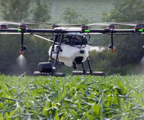
Spray application by drone is here. It’s common practice in South East Asia, with a very significant proportion of ag areas now treated that way. Estimates from South Korea, for example, suggest about 30% of their ag area being sprayed by drone. It’s in the US, too. The Yamaha RMax and Fazer helicopters, which pioneered drone spraying in Japan dating back to the mid 1990s, have been approved for use in California since 2015. DJI, the world’s largest drone manufacturer, introduced their ag model, the Agras MG-1, to North America in 2016. Many other spray drones are available or in development.
As William Gibson, the author of Johnny Mnemonic, once said,
“The future’s here, it’s just not widely distributed yet.”
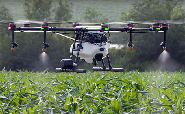
DJI Agras MG-1 spray drone (Source: DJI.com)
Proponents of drone spraying cite a drone’s ability to access areas where topography is a problem, such as steep slopes, where productivity of manual application is much lower, or low areas where soil moisture prevents ground vehicles. Operator exposure is reduced compared to handheld application.
Opponents talk about productivity and cost factors compared
to manned aerial application, spray drift, and rogue use.
Before drone spraying becomes commonplace, two important
things need to happen.
Federal laws need to be updated to accommodate the unique features of remotely piloted aircraft systems (RPAS), as they’re now called. Current laws make many assumptions unique to manned ships, and the process to correct that will require some patience. A thorough review for US laws, and their shortcomings, can be found here.
Federal pesticide labels need to permit the use of drones for application. As of August, 2021, Canadian labels have no such registered use.
There is no doubt that we need to prepare for a future that includes spraying by drones. Features such as topography adjustment for height consistency and autonomous swath control are already essentially standard, and the capabilities that improve control and safety will continue to develop.
And yet I’ve been nervous about the prospect of pesticide application with drones. My primary concern is around – you guessed it – spray drift. Because a drone payload is relatively small (about 5 to 25 L, depending on the model), application volumes will need to be low to have any sort of productivity. How low? For manned aircraft with a 200 to 600 gallon hopper, 2 to 4 US gpa (18 to 36 L/ha) are the lowest commonplace volumes. The lower volumes require a Medium spray quality (among the finer sprays in modern boom spray practice) to achieve the required coverage.
It’s a simple concept: the less water is used, the smaller the droplets need to be to provide the necessary droplet density on the target. Drift control with coarser sprays requires higher volumes, and true droplet-size-based low-drift spraying can’t really happen at volumes less then, say 5 to 7 US gpa.
At 2 to 4 US gpa, a drone would be able to do perhaps 1 acre per load. While OK for spot spraying, it represents a serious productivity constraint for anything larger. There will be a push toward lower volumes, perhaps 0.5 to 1 gpa (5 to 10 L/ha). The only way these will provide sufficient coverage is with finer sprays, ASABE Fine to Very Fine, with expected problematic effects on off-target movement and evaporation. These fine droplets are also more prone to the aerodynamic eccentricities of aircraft.
Vortices from the rotor can create unpredictable droplet movement (Source: kasetforward.com)
The current regulatory models for aerial drift assessment in North America, AgDISP and AgDRIFT, are not yet able to simulate drone application. But by entering finer sprays into these models for their conventional manned rotary wing aircraft, we can see that buffer zones will be higher. Much higher. And that outcome will give pause to regulators. Failure to control the movement of a spray is, and should be, a problem.
Estimated Buffer Zones (calculated by AgDISP) for a reference rotary wing spray aircraft, using three pesticide toxicologies and two spray qualities.
Furthermore, ultra-low volume (ULV) sprays can change the efficacy of some products, and these will require new performance studies. At this time, regulators are seeking information not just on spray drift, but on product efficacy, operator and bystander exposure, and crop residues.
Regulators are currently collecting spray drift and efficacy data from drones. Since the drones available in today’s market do not conform to a common design standard like fixed or rotary winged manned aircraft, each model may have its own characteristics and need its own study. Some will have rotary atomizers, others will use hollow cone hydraulic sprays. Some will have electrostatic charging, others may propose special adjuvants.
Once data are assessed, there will likely be restrictions in flight height, flight speed, wind speed, spray quality, water volume, perhaps air temperature and relative humidity (or Delta T). This is not new to spraying, as current labels already constrain use for both ground and aerial spray application, more so for aerial.
The obvious question is how these proper application practices can possibly be assured. Operators will need more than just regulatory approval to use a drone, they will require proper training, similar to what a commercial aerial applicator now receives prior to operating a business.
Recall that our aerial applicators are governed by national organizations, the NAAA in the US and the CAAA in Canada. These organizations are in regular contact with federal regulators to assure compliance. They also help fund research into application efficacy and safety. They organize conferences in the off-season and calibration clinics in the growing season. At these, flow rates are confirmed and deposited droplet size is measured. Spray pattern uniformity is assessed and corrected as necessary.
Should drone applications be exempt from these controls? I don’t think that would be wise. Are we ready to implement them? Absolutely not.
These requirements would change the drones’ economic model. And despite these precautions, a drone may still leave the control of a pilot due to unforeseen technical or human events.
In the US, Yamaha does not sell their drone helicopters. Instead, they deploy their own teams to make the applications. This way, they have assurance that only trained and experienced pilots use the technology.
As the industry gears up for the first registrations, we see drone service companies take a leading role in testing. Much is being learned via legal applications of liquid micronutrients, for example, or limited use of pesticides under approved research permits. And I’m pleased to see the recognition of drift management in these efforts through the use of low-drift nozzles. We are off to a promising start.
Requests for drone use are in progress at our regulatory agencies. The outcomes of their risk assessments will provide important initial guidance, and food for thought and discussion. In the meantime, the drone development continues at a rapid pace, with new features and greater capacity at each iteration.
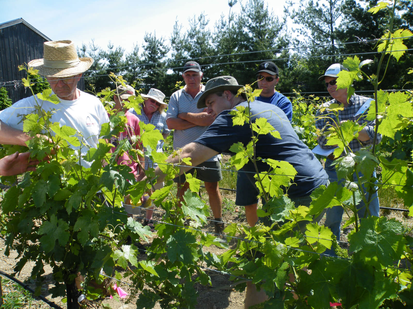
Checking coverage on water-sensitive paper with some of the Grape Growers of Ontario members in 2012Press play to hear the audio version of this article.
When an extension specialist, equipment retailer or consultant is asked to calibrate an airblast sprayer, they would be well advised to calibrate the sprayer operator as well.
Consider this: you and the operator are each investing three hours (average) to optimize the sprayer for a specific set of circumstances: the crop dimensions, density, and the weather conditions at the time of calibration. Depending on the reason for the application, you may even account for the product(s) mode of action and the pest location. This means that once you leave, the circumstances will change and the benefits of your efforts will quickly diminish.
Calibrations, like milk, have an expiry date.
There are three possible outcomes from a single, stand-alone calibration:
The operator manages efficacious applications throughout the season because the variability in weather, crop and pest isn’t significant. This is generally not the case.
Not recognizing that sprayer settings need constant adjustments (or being unable to make the changes) the operator experiences only modest results and decides calibration isn’t worthwhile.
The operator experiences failures and lays the fault with you (as the last person the touch the sprayer) and/or the agrichemical rep that sold the chemical. Few sprayer operators blame timing or spray coverage.
Explaining how to place water-sensitive paper and ribbons in an apple tree
The solution lies in the proverb “Give a man a fish and you feed him for a day; teach a man to fish and you feed him for a lifetime.” It is the sprayer calibrator’s responsibility to involve the sprayer operator and ensure they understand what is being done, why it is being done, and how to do it when you leave. Otherwise, expect to calibrate that sprayer again… soon.
Personally, I have had the most success educating and empowering sprayer operators to make their own seasonal adjustments based on a formulaic approach. Depending what you are trying to accomplish, you may not need all of the following steps, or you may perform some on your own and others as part of the education:
1) You could be working one-on-one, or you may be presenting to a large group. When it’s the latter, I like to arrive the day before to meet the host or owner of the sprayer(s). You can scope out the operation and triage the equipment so you know what parts you might need the next day. It also helps to see the space you will be working in.
2) Perform a pre-calibration inspection of the equipment with the sprayer operator. They know their equipment and can tell you about usage, history and maintenance. It also opens a dialogue between you and helps the operator to relax. Remember: from their perspective they may feel they are being judged and they will take criticisms and corrections personally. Do your best to reassure them that you are trying to make a good thing better – not to correct failings.
3) If you’re working at a large operation, educate the manager (decision maker) and the operators (drivers) at the same time. If you teach the manager, they might not effectively communicate the lessons to their operators. Likewise, if you teach the operators, they may not be able to convince the manager to let them spend money, or time, on making changes to the sprayer program. Get everyone on the same page, at the same time.
4) With the operator, perform a basic maintenance check. Specifically, confirm sprayer ground speed, evaluate pressure gauge accuracy and evaluate nozzles. Explain what you are doing, and ask the operator questions. This is where you learn about their attitude. Are they open-minded about changing how they do things? How has their efficacy been in the past? Will they spring for new parts? Do they need convincing that this process must be repeated regularly?
Demonstrating how deflectors aim air, and spray, into the target using some scrap wood.
5) With the sprayer in the crop, have the operator tie wind-indicator ribbons in the canopy (or better, use lengths pre-tied to springback clips). Explain what they are doing and why. Tell them these ribbons should be monitored, maintained and replaced season-long.
Here’s a tip: If you are working with a large audience, keeping them focused is critical. Growers will take the opportunity to catch up with each other while you are occupied with the sprayer. They are also inclined to wander away to answer cell phones. If they are not focused, you are on a service call and are not really educating. If you feel you are losing control, single out the ringleaders or wayward students and give them jobs, such as holding tools, or placing/removing water sensitive papers. When they have a responsibility, they pay closer attention.
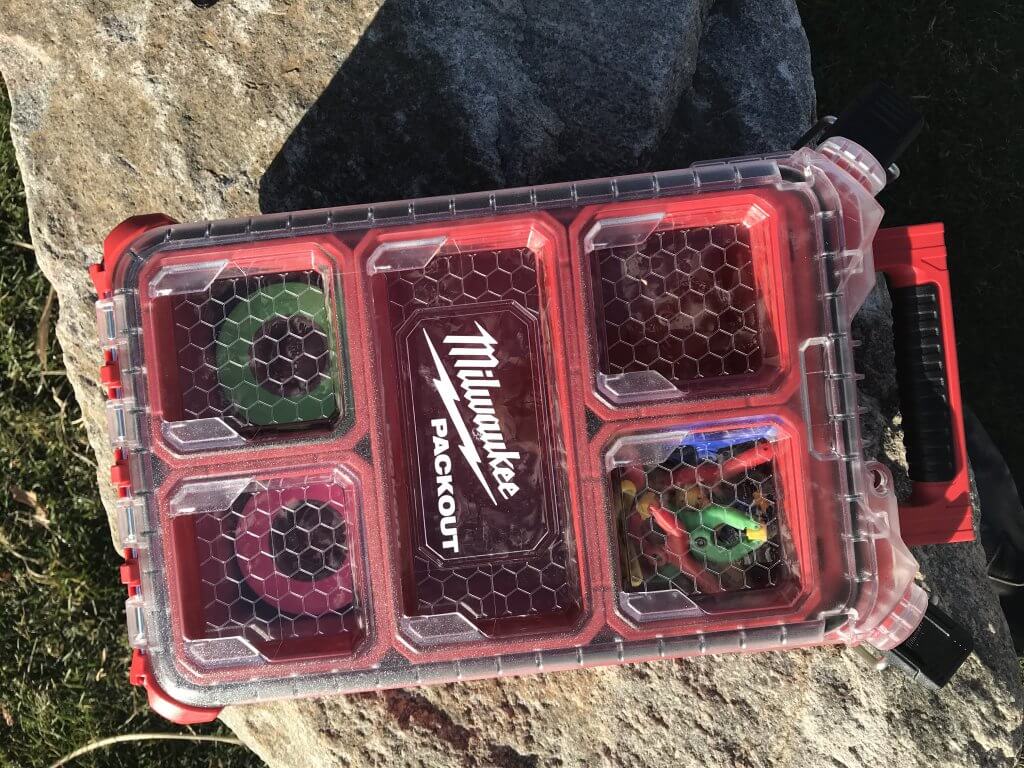
A convenient, weather proof calibration kit for flagging tape, clips and water sensitive paper.
6) Discuss where water-sensitive papers should go, and how they should face. Give the operator a latex glove and after you write on the back of each card (position and trial number) have them clip them in place. Tell them how much they cost, where to buy them and the benefits of using them regularly.
7) Have the operator spray the target crop using their typical set-up (i.e. ground speed, pressure, rate, air settings, etc.) Have attendees and the operator watch the ribbons as the sprayer passes. Spray from one side with both booms on and then stop to discuss results. Then spray from the other side and explore the cumulative impact.
8) The operator will be very surprised to learn they have drenched or missed the papers. They may or may not be surprised to have seen the ribbons stood straight out (indicating too much air). If you like, you can even set up papers in the next alley (or alleys) to show how much spray blew through the target. When the papers are dry enough, collect them and store them somewhere safe for later comparison. They tend to blow away, so stick them to a whiteboard with two-sided tape, or clip them there with paperclips. Explain that they can (potentially) save a lot of money and lost fill-time by improving their efficiency. Get them on-board for the big change to come.
9) Optimize sprayer ground speed, air direction (i.e. deflectors) and air speed/volume (i.e. fan speed). Then re-nozzle the sprayer using brass disc and core tips to reduce output in areas that were drenched or increase output in areas of sparse coverage. Quite often, I turn off the lowest (and sometimes, highest) nozzle positions. A piece of water-sensitive paper at the top and bottom of the canopy will confirm the wisdom in this. Label a new set of papers and have the growers position them in the same locations. Spray again. This entire process should take about 1/2 an hour and is described in detail in the Airblast101 handbook.
Tying flagging tape in trees to indicate prevailing wind and to calibrate airblast air settings.
10) The goal is 85 medium droplets per square centimetre and 10-15% coverage on 80% of the target surfaces for most insecticides and fungicides. If there are still drenches or misses, or if you’ve gone too far in a few positions, correct them and try once more. This is iterative. Make sure the sprayer operator will not be spraying in particularly hot or windy conditions, or your calibration at the top of the target can be compromised. Once you are both satisfied, work out the new sprayer output per area (e.g. US gpa or L/ha). You will have to discuss whether the operator plans to concentrate the tank mix to maintain the labelled “per area” rate (not recommended by me) or will continue to mix the tank as always and simply drive further on it (recommended by me). The later is called “Crop-Adapted Spraying“. Don’t push because it’s their livelihood, and therefore their choice.
11) The final step relies on how well you’ve earned the sprayer operator’s trust throughout this process. Once you have an output and spray distribution that you are both happy with, the operator should invest in molded ceramic tips that emit similar rates to replace the brass disc-core. Then, they must be willing to repeat the process on any crops that are significantly different to ensure they have the right settings. Sometimes only modest changes are required between blocks. Perhaps they will dedicate certain sprayers to certain blocks to reduce the number of changes required. In either case, they will have to revisit these settings as the season progresses to compensate for denser and/or larger canopies.
A few examples
The following figures illustrate three airblast calibrations in Ontario apple orchards from spring 2014. Some required one attempt; others required a few trial settings before we achieved reasonable coverage. In all three cases, the sprayer operators reduced per-area rates, bought new nozzles and planned to buy water-sensitive paper. Further, they indicated they would continue to monitor ribbons (as long as they could be seen) and would review coverage after petal-fall.
Several nozzles shut off, spray re-distributed. Targets still drenched in two locations with a 24% savings in spray mix.Three successive re-calibrations were required. Output was reduced in the first trial, but poor coverage in position 3. Top nozzles turned off and spray re-distributed in trial 2, but a gust of wind reduced coverage at the top of the tree. Bottom nozzles turned off and spray redistributed to top nozzles for a 40% savings in spray mix.Output reduced in all nozzle positions and sprayer fan speed reduced. The high humidity greatly reduced droplet evaporation and increased the spread on the papers. In this case, it was decided not to reduce output any further to account for anticipated growth and the high humidity. There was a 27% savings in spray mix.
Conclusion
So, the next time you calibrate an airblast sprayer, be sure to teach the sprayer operator (and audience) what you are doing and why. Involve and engage them. Answer their questions. Encourage them to perform the same calibration for each significantly different block and make mid-season changes. With luck they will only call back to report success and savings, and not to condemn your efforts, or worse: to ask you to re-calibrate their sprayer!
A lot of people are intimidated by sprayer plumbing. One look at the spaghetti bowl of spray mix and hydraulic hoses and valves, and they walk away. It hasn’t helped that much of it is concealed under the frame and all of it is in the same black colour, so figuring it out on your own is almost impossible.
Belly of a typical sprayer, showing black hydraulic and spray hoses.
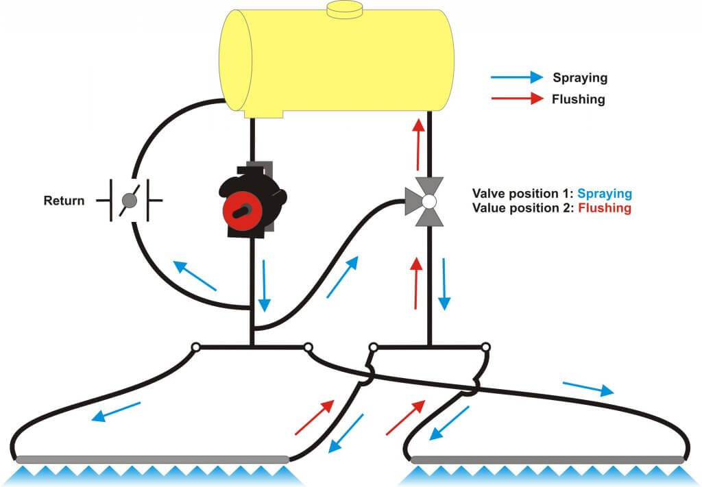
Let’s quickly review the basics. In all sprayers, the liquid in the tank is drawn out from the bottom and pressurized by a pump. The pressurized liquid is split into two main paths. One goes to the spray boom to hydraulic atomizers (nozzles). The other goes back to the tank to agitate the liquid and act as a pressure bypass when the booms are off. Bypass throttling changes pressure. That’s it.
Sprayer plumbing diagram (Source: TeeJet).
By the way, has anyone ever thought of some colour-coding or labelling the hoses and valves on a sprayer? We’d definitely appreciate that.
Conventional boom sections
Most North-American sprayers feed the pressurized liquid to the boom, where the flow is subdivided into physical sections that define the various portions of the boom that can spray at any one time. Older sprayers might only have two sections, the left and the right boom. Wide booms now have anywhere from 5 to 13 sections, each about two to four metres wide. Each section has a pressure feed to its middle, and each section terminates at two dead ends, at which we place caps or valves for flushing.
A conventional plumbed boom with two sections. Each section has two terminal ends that require cleaning. Boom can only be flushed or primed by spraying or by opening boom end caps.
Sprayer with nine sections, each controlled by its own valve and each running a dedicated feed hose.
Two partial boom sections, each showing a central feed line and a capped boom end.
Sectional boom end showing 10 cm of capped pipe beyond last nozzle body.
Boom end with valve to facilitate draining and flushing.
Any liquid that enters this type of boom must exit at the nozzle or the boom end. It must be sprayed out or drained. This poses three distinct problems.
If the boom contains water or a previous spray mix, the boom needs to be primed with the new product before spraying. We need to spray or drain the existing product out.
If we want to clean the boom or flush it with water, again we need to push the existing liquid out.
If we have dead spots in the boom section, such as a boom end, we need to take special care to flush those out as well.
These characteristics complicate cleaning, create waste or contamination, and take time.
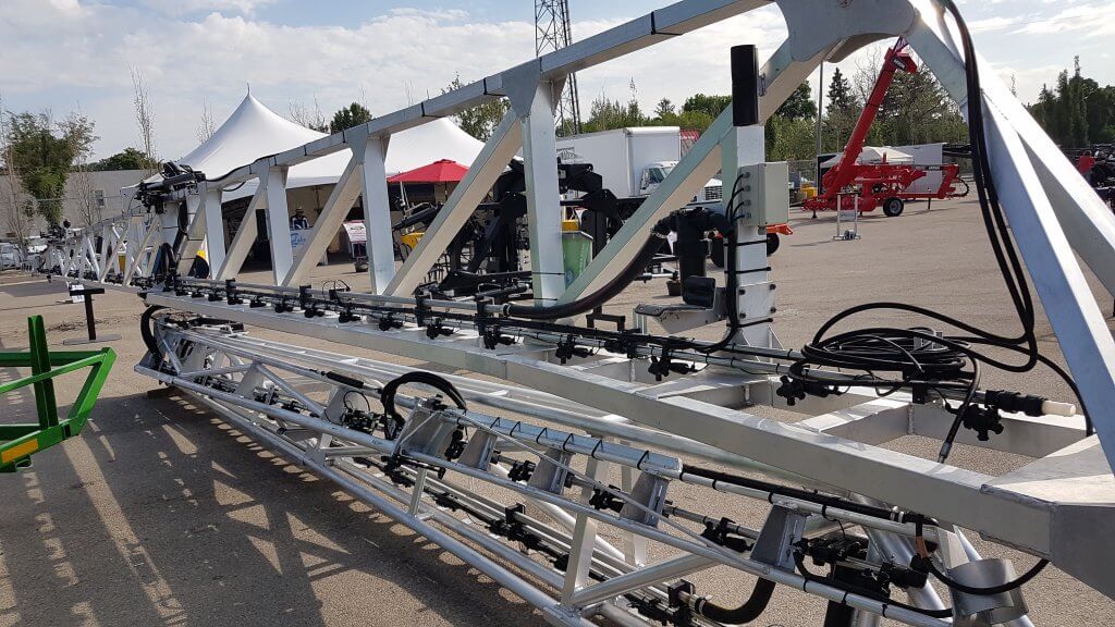
Recirculating booms
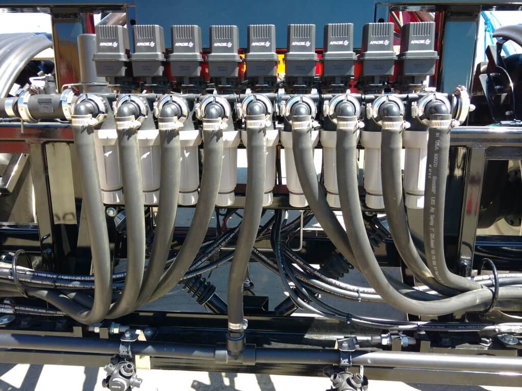
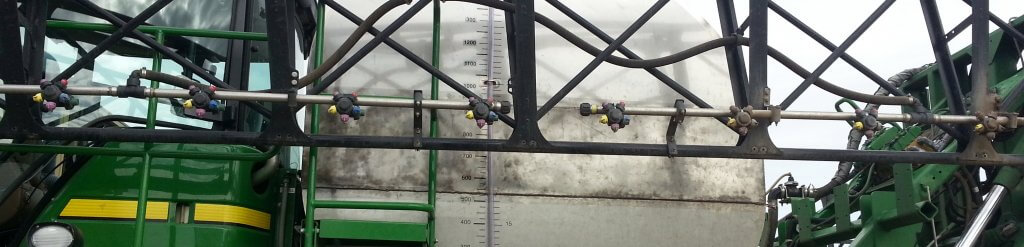
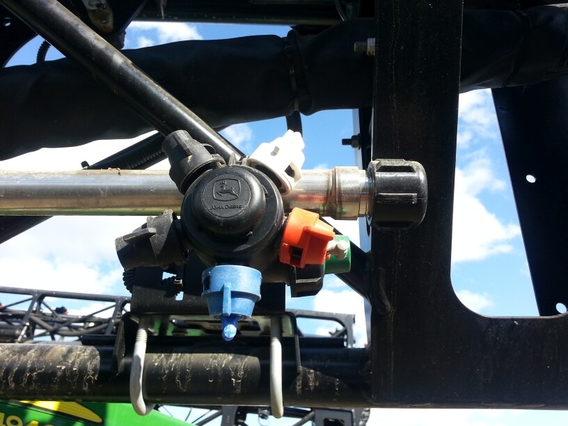
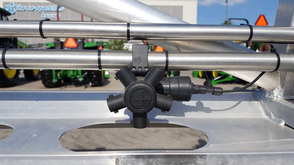
In a recirculating boom, the spray mixture enters the boom at one end and exits at the other, returning to the spray tank. In most cases, the left and right wing each has its own feed and return. Sectional control is achieved via individual valves (air or electric) placed on the nozzle bodies.
There are two main types of recirculating booms on the market.
The first system routes the pressurized mixture into the boom and shuts off the return line during spraying. When the nozzles are shut off for a turn, the return line opens automatically and the boom flow is pushed past the nozzles back to the tank. When the nozzles spray again, the return line closes to pressurize the boom.
Recirculating boom system offered by Pommier. One end of boom is pressurized, the other end is return. Return flows when boom spraying is shut off. Boom can be primed or flushed without spraying.
This is the system used by Pommier, the French aluminum boom manufacturer who first introduced recirculating booms to North America.
Pommier recirculating boom.
Pommier boom showing stainless steel supply and return lines, as well as air-activated shutoff valve on nozzle body.
The second type of system contains a 3-way valve, connected to the return line and the pressure side of the pump. This valve provides the option of either allowing the return line to go back to the tank, as above, or to also allow pumped flow to the return side so that the boom is pressurized at both ends.
Recirculating boom that allows return line to be either pressurized by pump, or return to tank.
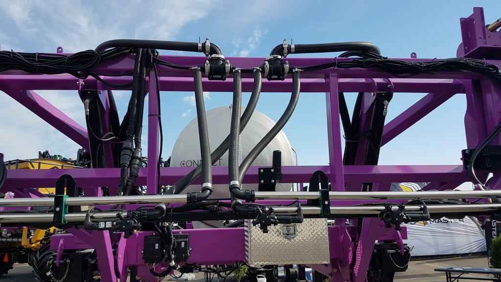
Top view of D.O.T. Connect sprayer recirculating boom setup. Lower line is pressurized by pump. Upper line is return. Three-way valve allows return line to either go back to tank, or be pressurized by pump.
Tidy setup of pressure and return lines on D.O.T. Connect system.
This feature may be useful with long booms along which pressure drop is more likely to occur, or when very high flows are required, and was introduced to North America by the Dutch manufacturer Agrifac, about which we wrote here and reprinted Mick Robert’s article from Pro Operator here. A similar system is available from Rogator (starting in 2018) via their C-Series featuring LiquidLogic. It has also been used on the Connect sprayer, developed by Pattison Liquid Systems, for the D.O.T. autonomous platform.
The main advantages of this design are that it provides the option of additional pressure to the spray boom to avoid pressure drop, and to allow any spray mix in the return line to be pushed and sprayed out to the boom for rinsing in the field. This lowers the remaining volume that needs to be diluted.
Agrifac recirculating boom showing return loop at boom end.
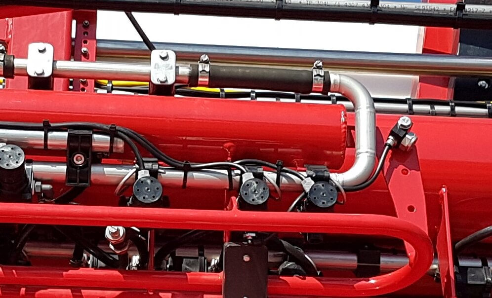
Boom end on Rogator Liquid Logic system. Note Hypro Pro-Stop E shutoff valve.
Features
Recirculating booms offer advantages in terms of preventing soil and water contamination and also in terms of simplifying the boom cleaning process. The design provides an opportunity to graduate to a better resolved sectional control as well due to the requirement for individual nozzle shutoff valves.
Due to shorter and less complex lengths of plumbing needed, stainless steel can be used for the return lines which decreases the potential for pesticide residue being adsorbed.
To rinse a boom with product mix still in the tank, simply draw water from the on-board clean water tank and push it to the boom without activating any nozzle bodies. The mix in the boom is returned to the tank and replaced with water, nothing is sprayed or drained. The tank contents may become slightly diluted depending on the duration of the rinse.
To rinse the tank as part of the sprayer cleanout, first spray the tank empty. Then introduce clean water into the product tank via the wash-down nozzles and spray that out. As always, either use several batches of small clean water volumes, or a continuous rinse system, to dilute the remainder most effectively. There may be additional volume to dilute from the return lines compared to a conventional system, depending on the type of recirculating system is used. However, boom ends no longer exist and this saves effort and ensures a more thorough rinsing.
To prime a boom that contains water, simply open the return lines back to the tank and allow the new mix to flow through the boom. Again, some dilution of the tank will occur due to the water in the boom.
The value of spray-free rinsing and priming adds up. Each prime, for example, consumes about 30 US gallons before the spray reaches the last nozzle of the longest section. Much of that product ends up on the ground, probably while the sprayer is stationary, and probably in a similar place on the field year after year.
Since a recirculating boom requires a powered individual nozzle shutoff, this adds some cost. However, the opportunity of improved sectional control via virtual sections is significant (most monitors offer 16 virtual sections that can be configured). Well-configured virtual sections can save several percent from overlaps.
Recirculating booms remove many of the contamination problems associated with conventional plumbed sections. They save time, money, and reduce environmental impact. We think they should be offered on sprayers.
Here’s a link to a nice article on recirculating booms written by Spencer Myers for the Manitoba Co-operator. A video that goes with the article can be found here.