Category: Speciality Sprayers

Main category for all sprayers that are not horizontal booms

  • Recirculating Booms – Introduction to the Concept

    Recirculating Booms – Introduction to the Concept

    Listen to the audio version of this article here

    A lot of people are intimidated by sprayer plumbing. One look at the spaghetti bowl of spray mix and hydraulic hoses and valves, and they walk away. It hasn’t helped that much of it is concealed under the frame and all of it is in the same black colour, so figuring it out on your own is almost impossible.
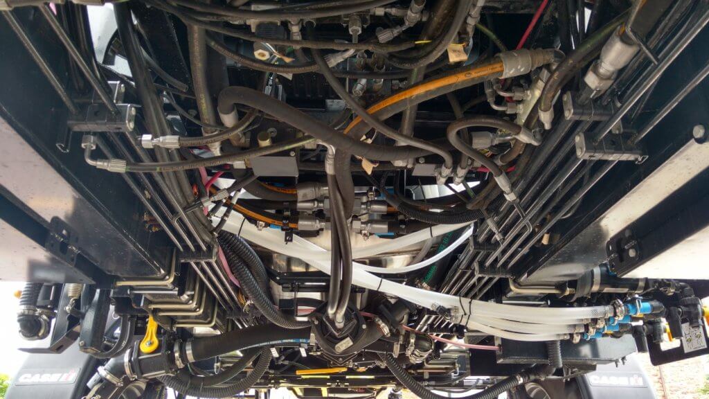
    Belly of a typical sprayer, showing black hydraulic and spray hoses.

    Let’s quickly review the basics. In all sprayers, the liquid in the tank is drawn out from the bottom and pressurized by a pump. The pressurized liquid is split into two main paths. One goes to the spray boom to hydraulic atomizers (nozzles). The other goes back to the tank to agitate the liquid and act as a pressure bypass when the booms are off. Bypass throttling changes pressure. That’s it.
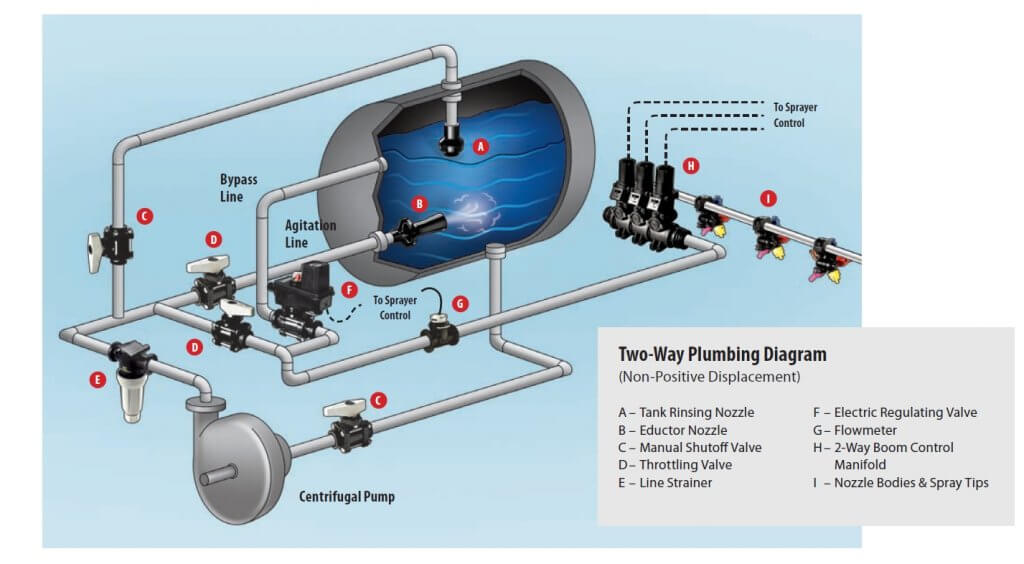
    Sprayer plumbing diagram (Source: TeeJet).

    By the way, has anyone ever thought of some colour-coding or labelling the hoses and valves on a sprayer? We’d definitely appreciate that.

    Conventional boom sections

    Most North-American sprayers feed the pressurized liquid to the boom, where the flow is subdivided into physical sections that define the various portions of the boom that can spray at any one time. Older sprayers might only have two sections, the left and the right boom. Wide booms now have anywhere from 5 to 13 sections, each about two to four metres wide. Each section has a pressure feed to its middle, and each section terminates at two dead ends, at which we place caps or valves for flushing.
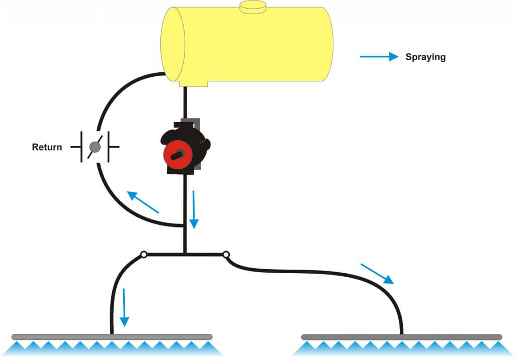
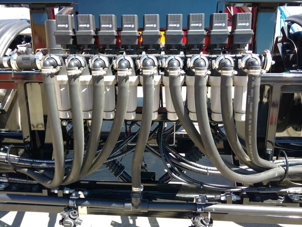
    A conventional plumbed boom with two sections. Each section has two terminal ends that require cleaning. Boom can only be flushed or primed by spraying or by opening boom end caps.

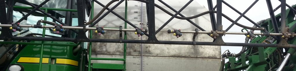
    Sprayer with nine sections, each controlled by its own valve and each running a dedicated feed hose.

    Two partial boom sections, each showing a central feed line and a capped boom end.

    Sectional boom end showing 10 cm of capped pipe beyond last nozzle body.

    Boom end with valve to facilitate draining and flushing.

    Any liquid that enters this type of boom must exit at the nozzle or the boom end. It must be sprayed out or drained. This poses three distinct problems.

    • If the boom contains water or a previous spray mix, the boom needs to be primed with the new product before spraying. We need to spray or drain the existing product out.
    • If we want to clean the boom or flush it with water, again we need to push the existing liquid out.
    • If we have dead spots in the boom section, such as a boom end, we need to take special care to flush those out as well.

    These characteristics complicate cleaning, create waste or contamination, and take time.

    Recirculating booms

    In a recirculating boom, the spray mixture enters the boom at one end and exits at the other, returning to the spray tank. In most cases, the left and right wing each has its own feed and return. Sectional control is achieved via individual valves (air or electric) placed on the nozzle bodies.

    There are two main types of recirculating booms on the market.

    The first system routes the pressurized mixture into the boom and shuts off the return line during spraying. When the nozzles are shut off for a turn, the return line opens automatically and the boom flow is pushed past the nozzles back to the tank. When the nozzles spray again, the return line closes to pressurize the boom. 
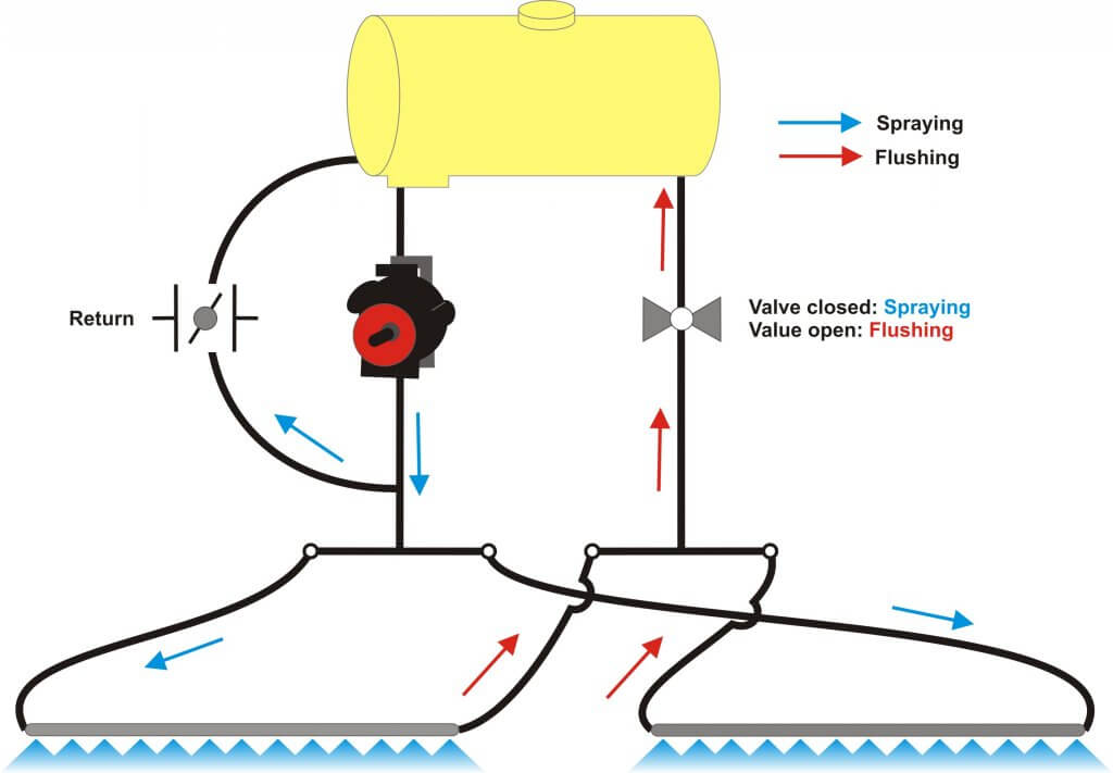
    Recirculating boom system offered by Pommier. One end of boom is pressurized, the other end is return. Return flows when boom spraying is shut off. Boom can be primed or flushed without spraying.

    This is the system used by Pommier, the French aluminum boom manufacturer who first introduced recirculating booms to North America.
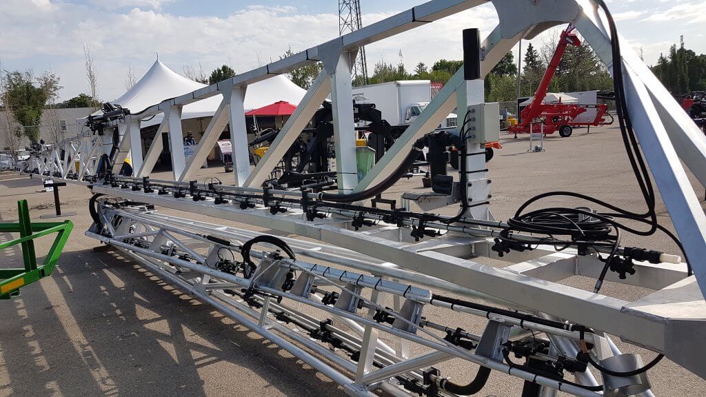
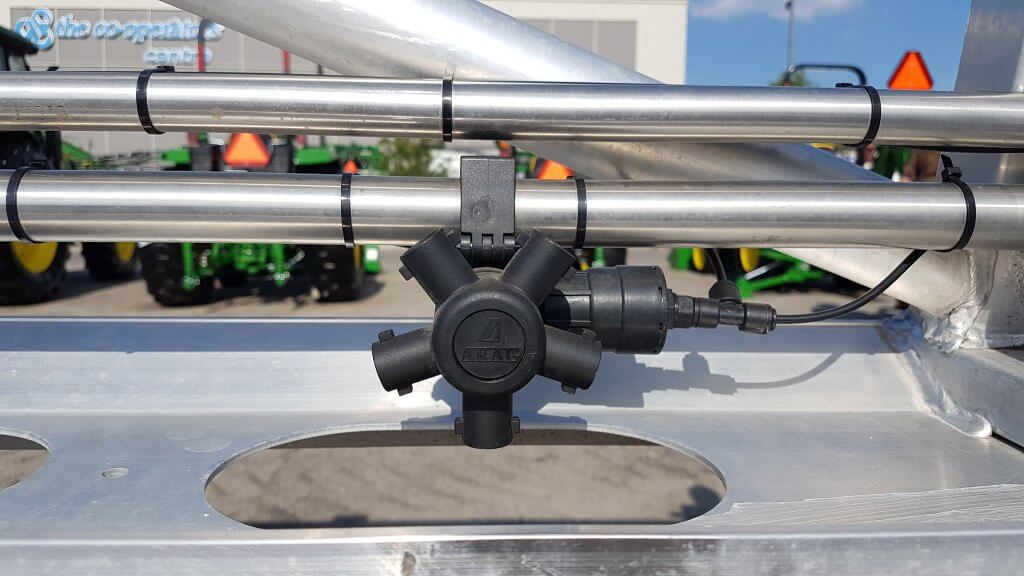
    Pommier recirculating boom.

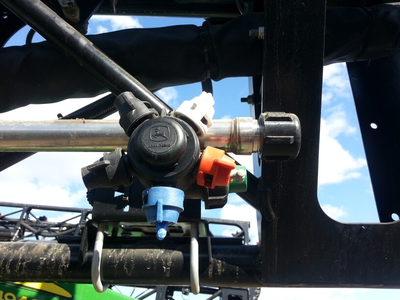
    Pommier boom showing stainless steel supply and return lines, as well as air-activated shutoff valve on nozzle body.

    The second type of system contains a 3-way valve, connected to the return line and the pressure side of the pump. This valve provides the option of either allowing the return line to go back to the tank, as above, or to also allow pumped flow to the return side so that the boom is pressurized at both ends.
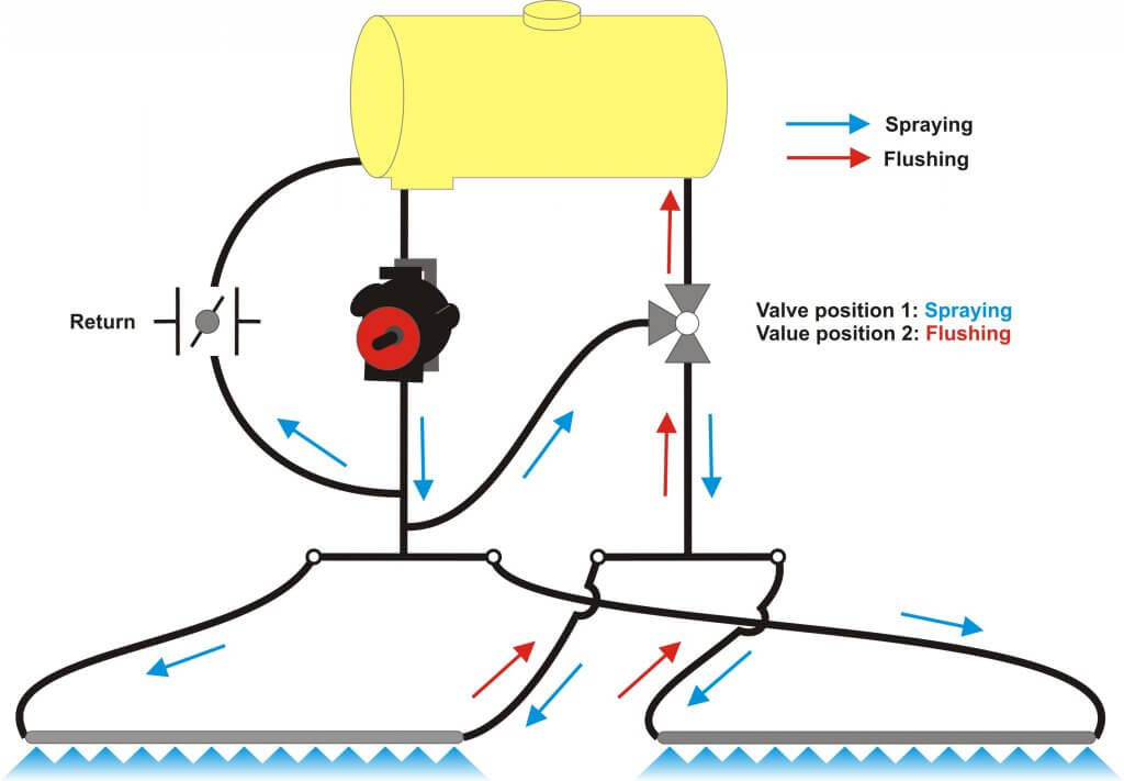
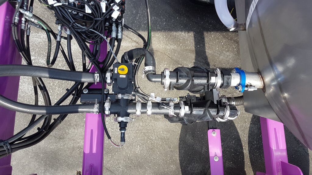
    Recirculating boom that allows return line to be either pressurized by pump, or return to tank.

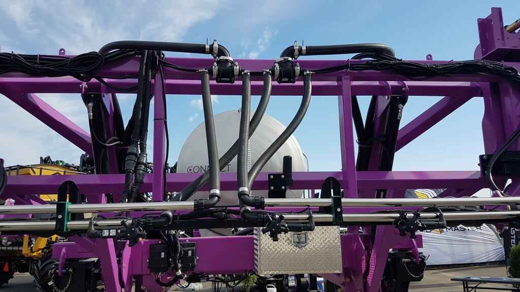
    Top view of D.O.T. Connect sprayer recirculating boom setup. Lower line is pressurized by pump. Upper line is return. Three-way valve allows return line to either go back to tank, or be pressurized by pump.

    Tidy setup of pressure and return lines on D.O.T. Connect system.

    This feature may be useful with long booms along which pressure drop is more likely to occur, or when very high flows are required, and was introduced to North America by the Dutch manufacturer Agrifac, about which we wrote here and reprinted Mick Robert’s article from Pro Operator here. A similar system is available from Rogator (starting in 2018) via their C-Series featuring LiquidLogic. It has also been used on the Connect sprayer, developed by Pattison Liquid Systems, for the D.O.T. autonomous platform.

    The main advantages of this design are that it provides the option of additional pressure to the spray boom to avoid pressure drop, and to allow any spray mix in the return line to be pushed and sprayed out to the boom for rinsing in the field. This lowers the remaining volume that needs to be diluted.
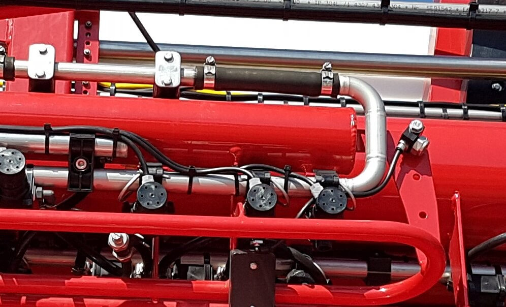
    Agrifac recirculating boom showing return loop at boom end.

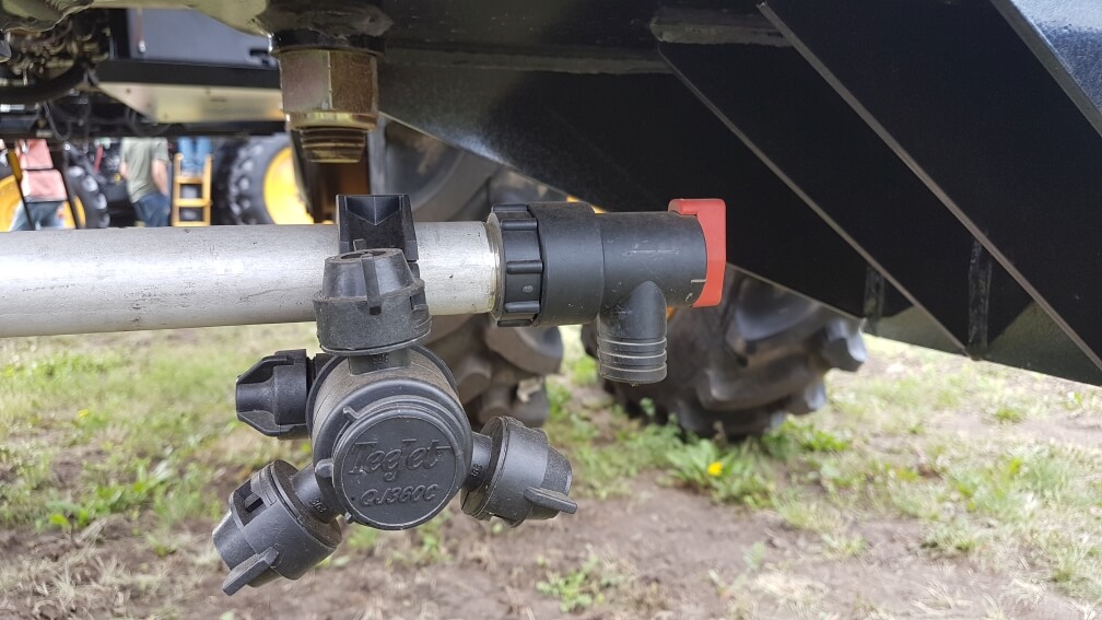
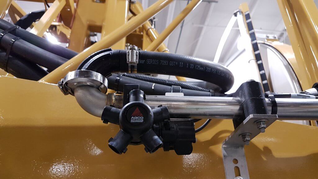
    Boom end on Rogator Liquid Logic system. Note Hypro Pro-Stop E shutoff valve.

    Features

    Recirculating booms offer advantages in terms of preventing soil and water contamination and also in terms of simplifying the boom cleaning process. The design provides an opportunity to graduate to a better resolved sectional control as well due to the requirement for individual nozzle shutoff valves. 

    Due to shorter and less complex lengths of plumbing needed, stainless steel can be used for the return lines which decreases the potential for pesticide residue being adsorbed.

    To rinse a boom with product mix still in the tank, simply draw water from the on-board clean water tank and push it to the boom without activating any nozzle bodies. The mix in the boom is returned to the tank and replaced with water, nothing is sprayed or drained. The tank contents may become slightly diluted depending on the duration of the rinse.

    To rinse the tank as part of the sprayer cleanout, first spray the tank empty. Then introduce clean water into the product tank via the wash-down nozzles and spray that out. As always, either use several batches of  small clean water volumes, or a continuous rinse system, to dilute the remainder most effectively. There may be additional volume to dilute from the return lines compared to a conventional system, depending on the type of recirculating system is used. However, boom ends no longer exist and this saves effort and ensures a more thorough rinsing.

    To prime a boom that contains water, simply open the return lines back to the tank and allow the new mix to flow through the boom. Again, some dilution of the tank will occur due to the water in the boom.

    The value of spray-free rinsing and priming adds up. Each prime, for example, consumes about 30 US gallons before the spray reaches the last nozzle of the longest section. Much of that product ends up on the ground, probably while the sprayer is stationary, and probably in a similar place on the field year after year.

    Since a recirculating boom requires a powered individual nozzle shutoff, this adds some cost. However, the opportunity of improved sectional control via virtual sections is significant (most monitors offer 16 virtual sections that can be configured). Well-configured virtual sections can save several percent from overlaps.

    Recirculating booms remove many of the contamination problems associated with conventional plumbed sections. They save time, money, and reduce environmental impact. We think they should be offered on sprayers.

    Here’s a link to a nice article on recirculating booms written by Spencer Myers for the Manitoba Co-operator. A video that goes with the article can be found here.

  • How Airblast Spray Droplets Behave (or Misbehave)

    How Airblast Spray Droplets Behave (or Misbehave)

    Listen to article here.

    Some pesticide labels require or prohibit certain droplet sizes to reduce the potential for drift. But, even when labels are silent about size restrictions, operators should be aware of the potential for droplet size to affect coverage. In the case of airblast, droplets should be:

    • large enough to survive evaporation between nozzle and target.
    • small enough to adhere without drifting off course.
    • plentiful enough to provide uniform coverage without compromising productivity (e.g. affecting refills and travel speed).

    Once spray leaves the nozzle, the operator has no more control over the application, so it’s important to plan for as many contributing factors as possible. Deciding which nozzles to use (and yes, you have alternatives beyond disc-core), requires an understanding spray quality symbols and basic droplet behaviour.

    Spray Quality

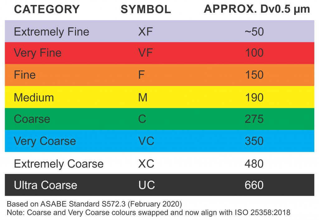
    Droplet diameter is measured in microns (µm). For a given pressure, a nozzle creates a range of droplet sizes which are described by the American Society of Agricultural and Biological Engineers (ASABE) standard S572.3 (Feb. 2020) In North America, these spray quality ratings range from “Extremely Fine – XF” to “Ultra Coarse – UC”. For interest, the scale is based on the British Crop Protection Council (BCPC) system, which is slightly different.

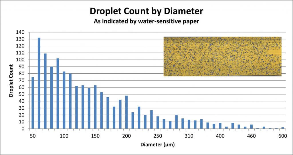
    To make sense of the spray quality rating, we must first understand that not every droplet produced by a hydraulic nozzle is the same size. We noted that a single nozzle produces a range of droplet sizes. Spray quality captures that span using a few key metrics. The first is the Volume Median Diameter (VMD) or DV0.5. Think of it this way: Let’s say you have a hollow cone nozzle that breaks a volume of liquid up into droplets. Let’s arrange them from finest to coarsest as in the following graph.

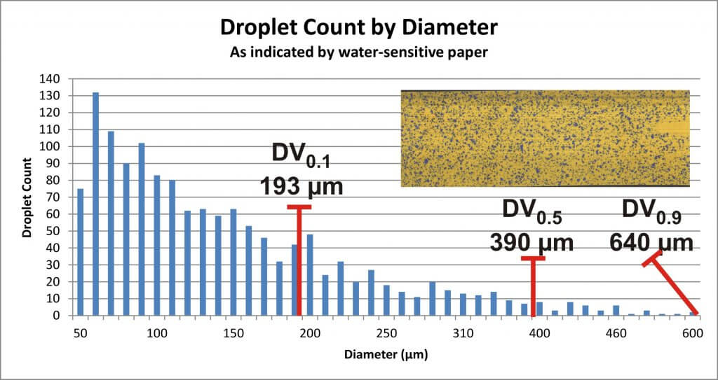
    The DV0.5 refers to the droplet size where half the spray volume is comprised droplets smaller than the DV0.5, and the other half is comprised of larger droplets. But we need more to understand the variation in the population. In other words, are they all the same size, or do they vary a great deal?

    That’s why we also assign a DV0.1 which tells us the droplet size where 10% of the spray volume is comprised of smaller droplets, and a DV0.9 which indicates that 10% of the spray volume is comprised of larger droplets. Let’s add them to the graph:

    With all three numbers, we can calculate the Relative Span (RS) by subtracting the DV0.1 from the DV0.9 and dividing by the DV0.5. The smaller the resulting number, the less variation there is in the spray quality. Two nozzles might produce a range of droplets with the same DV0.5, but the one with the larger RS is more variable, and is more likely to drift. Since we don’t typically have access to the RS of each nozzle, we rely on the spray quality symbols in nozzle catalogues to alert us to potential drift issues.

    Relative Droplet Size

    Did you notice in the graph that there are a lot of Fine droplets compared to Coarse?  Disc-core (or disc-whirl) nozzles do not have spray quality ratings, and moulded hollow cones may or may not. This is, in part, because the standard was developed for flat fan nozzles, but mostly it arises from the nature of airblast spraying. No matter the original droplet diameter, the air shear from the sprayer and the distance-to-target reduce the DV0.5 considerably by the time spray reaches the target. It is safe to assume that the final spray quality will be much finer than the nozzle’s rating.

    Incidentally, this is a big difference between boom sprayers and airblast: Where the boom sprayer operator should be aware of how pressure affects droplet size, it’s of little consequence to an airblast operator. On an airblast sprayer, pressure really only affects nozzle rate.

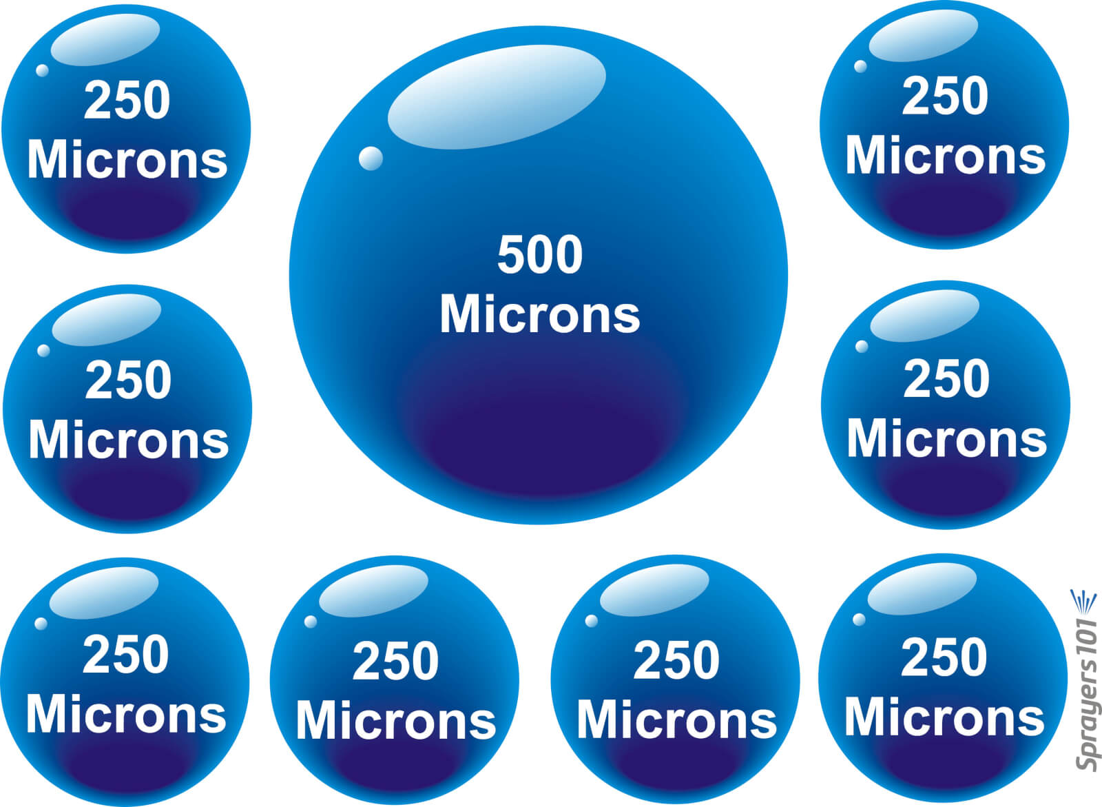
    So, while shear and evaporation raise drift potential, shear also increases droplet count. Imagine the volume a nozzle emits as a cake. No matter how many slices you cut the cake into, you still have the same amount of cake. The finer the slices, the more people can have a slice, albeit not very much. Similarly, a single Coarse droplet can contain the same volume as many finer droplets. Mathematically, a droplet with diameter X represents the same volume as eight droplets with diameters of 1/2X. See the illustration below:

    The one to eight rule: Every time the median diameter of spray is doubled, there are eight times fewer droplets. Conversely, every time the median diameter of spray is halved, there are eight times more.
    The eight to one rule: Every time the diameter of a droplet spray is doubled, there are eight times fewer droplets. Conversely, every time the diameter of a droplet is halved, there are eight times more.

    Droplet Behaviour

    The droplets that comprise the spray behave differently from one another. Finer droplets have a low settling velocity, which means they take a long time to fall out of the air. Conversely, coarser droplets fall out of the air more quickly. Think of how a ping pong ball (the finer droplet) has much less mass than a golf ball (the coarser droplet). When thrown into the wind, the golf ball follows a simple trajectory before falling. The ping-pong ball behaves erratically, like a soap bubble. Wind, thermals, humidity and many other factors will change where it goes because it is too light to resist them. It may even land behind the thrower, blown by the prevailing wind.

    It is because of the behaviour of finer droplets, and the airblast sprayer’s inclination to create them, that we must be so diligent when we adjust the air settings.

    We once explored this at a nursery workshop. The operator was spraying whips, which are young trees with very few lateral branches. He used a cannon sprayer to cover 30 rows (15 from each side) and felt he would incur less drift if he just used pressure, not air, to propel the spray. Water sensitive paper exposed the erratic coverage that resulted. Coverage uniformity was greatly improved when air was used, even when only spraying from one side of the 30 row block. Of course, this was only to demonstrate a principle; we don’t recommend alternate-row-middle-spraying.

    Air-induction nozzles can be used to increase the median droplet size on an airblast sprayer. When used in the top nozzles positions, the coarser droplets that miss the top of tall targets will ultimately fall (reducing drift). They can also be used in positions that correspond to restricted airflow. In this case the operator relies on pressure to propel the coarser droplets where there is limited air to carry finer droplets.

    Conclusion

    The net result of all this is that the sprayer operator must choose a nozzle, pressure, and travel speed while considering the effect of distance-to-target and the weather. The resultant range of droplets should be fine enough to increase droplet count and be carried by sprayer air to deposit uniformly throughout the canopy. However, droplets should also be coarse enough to reduce drift if they miss.

    Hey, if it was easy, anyone could do it!

    Move ahead to 29:40 to watch a video describing how droplets behave an misbehave. Ahhhh Covid-hair. It was a thing.

  • Do Labels Help us Apply Pesticides Properly?

    Do Labels Help us Apply Pesticides Properly?

    It happened three times this spring.  As is often the case, I was contacted by growers who wanted help with herbicide application.  In most of these calls, the discussion revolves around the proper choice of nozzles for a specific task, perhaps some questions on spray pressure, water volume and travel speed.

    But these three were different.  Instead of being seasoned applicators, all three were new to the business.  And more importantly, they had done their homework by looking at product labels before calling.

    Labels give us important information on product rates, crop and weed staging, mixing order, sprayer cleaning, and personal and environmental protection.  They’re very valuable there.  But they also provide application information, and that’s where the problems begin.

    Perseverance Required

    I have to commend my three clients:  they showed great tenacity by actually finding application information on a pesticide label in the first place.  This document is so mired in legalese protectionist language at the front that it discourages all but the most persistent.

    And often, the application information comes in several parts, interspersed among other information.  Mixing instructions.  A little later, application. Somewhere nearby, buffer zones.  Another paragraph for cleaning.  Rainfastness?  Keep looking.

    It forces the reader to skim through the document, hunting for relevant information.

    But once my clients found application instructions, they obviously questioned if they should believe it, or else they wouldn’t have called.  The application statements on many labels, simply put, are from long ago, and it’s obvious.

    Consider the following two label excerpts, the first from a product initially registered in the mid 1980s and still available, the second from one registered about 30 years later:

    1980s:

    Application should be made using a minimum of 55-110 litres of water per hectare, at a pressure of 275 kPa, or 310 kPa if using check valves, and at a ground speed of 6-8 kph.

    The use of 80° or 110° flat fan nozzles is recommended for optimum spray coverage.

    Do not use flood jet nozzles, controlled droplet application equipment or Sprafoil® equipment.

    Application of the spray at a 45° angle forward and higher water volumes will result in better spray coverage and penetration of the crop canopy.

    Uniform, thorough coverage is important to obtain consistent weed control. Higher water volumes should be used under dense crop and weed canopies to ensure thorough coverage of the target weeds.

    2010s:

    Apply in a spray volume of 46.8 – 93.5 L/ha unless otherwise specified in tankmix partner section of this label – at 207-345 kPa (30-50 PSI) pressure to ensure proper weed coverage.

    Flat fan nozzles of 80° or 110° are recommended for optimum coverage.

    Do not use floodjet or controlled droplet application equipment or Sprafoil® equipment.

    Nozzles may be oriented 45° forward to enhance crop penetration and to give better weed coverage.

    Uniform, thorough coverage is important to obtain consistent weed control. Higher water volumes should be used under dense crop and weed canopies to ensure thorough coverage of the target weeds.

    Thirty years apart, but remarkably similar.

    Crop protection companies spend about 10 yrs. and $250 million to produce a new pesticide and register it for use.  Having made this commitment, it would be most useful to see a small further investment to provide current application information that is relevant to applicators.

    After all, these applicators purchase the active ingredient to provide a return on this multi-million dollar investment, to the tune of about 2 billion dollars per year in Canada alone. They deserve good application information.

    Imagine this scene:

    “Doctor, thank you for this new high tech pharmaceutical engineered to help me with my serious illness.  How should I take it?”

    “Not sure.  Here, read this cough syrup label I found in my drawer.  Should be pretty close.”

    It’s clearly ridiculous

    Let’s dissect these labels to see how they could be improved.

    Flat fan nozzles of 80° or 110° are recommended for optimum coverage…

    Our sample labels refer to what we assume are conventional flat fan nozzles.  While popular in the 80s, these have all but disappeared from sprayers over the course of the past 20 years or so.  We haven’t recommended them since then because they drift too much. They’ve been replaced by low-drift nozzles, either pre-orifice, or air-induction.

    Nozzle fan angles are now generally 110 degrees or more, and frankly, the difference between 80 and 110 degrees is not that important.  What’s important is proper overlap, achievable with a visual assessment followed by boom height and pressure adjustments.  Unfortunately the label is silent on that.

    Application should be made … at a pressure of 275 kPa, or 310 kPa if using check valves…

    A nozzle’s recommended operating pressure depends on the specific nozzle model and on the spray quality (average droplet size) required. With literally many dozens of nozzles now available to each applicator, general pressure suggestions are likely to be wrong, and are more of a liability than a help. And they force label non-compliance when over-ruled by a nozzle manufacturer’s recommendations.

    Speaking of spray quality, growers crave to know at what spray quality a product should be applied for best performance and lowest drift. Some labels refer to spray quality (e.g. “apply with a Coarse spray”), but this is with reference to spray drift and buffer zone distances, not efficacy, and that distinction is not made.  Knowing the right quality for efficacy would help applicators choose the right nozzle and pressure to meet that criteria.

    Higher pressures if using check valves?  Nobody has brass screens with check valves anymore.  Sprayers have had modern diaphragm check valves for a generation, and those don’t produce pressure losses.

    And we all know that six to eight km/h is hardly a common speed these days.

    Do not use floodjet or controlled droplet application equipment or Sprafoil® equipment

    Sprafoil nozzles have not been produced in Canada for about 25 years, in fact their manufacturer is no longer in business.  Controlled droplet atomizers, while becoming more popular again on aircraft, were last seen on ground sprayers in the 1980s. Even then, total installed numbers were probably in the single digits.

    As for FloodJet nozzles, those went out of style for herbicides in the late 70s, and were replaced by the very successful TurboTeeJet nozzles shortly after.

    Nozzles may be oriented 45° forward…

    Nozzles are rarely tilted 45 degrees forward for herbicide application anymore.  Maybe that’s because spray booms aren’t built that way today, or because modern booms on self-propelled sprayers are now about 30” (75 cm) above ground, and we travel at about 15 mph (22 km/h).  So the forward tilting, though shown to be effective for grassy weeds at 5 mph (8 km/h) and 20” (50 cm) boom heights, as researched in the 1970s, isn’t relevant for herbicides with higher booms.

    Uniform, thorough coverage is important to obtain consistent weed control.

    Statements advocating for good coverage are nice, but they aren’t useful.  Everybody knows we want good coverage.  What applicators need to know is how they should measure coverage, and what good coverage actually is.  Can we use water-sensitive paper?  How much of the target should be covered?  How many droplets should be in each square centimetre?  How can we measure that in the field, right now? How does it depend on the crop canopy, on weed stage, and on spray quality? The more information an applicator gets, the higher the chance of success.

    Apply in a spray volume of 46.8 – 93.5 L/ha…

    The only statement that survives our little examination is about water volume. Water volume is important.  But even there we have a problem.  The volume is in L/ha.  This is useful in some parts of Canada, but not in the west, where producers communicate primarily in US gallons per acre.  And in the west, provincial guidelines have generated this odd hybrid of L/acre, which few people use for spray volume.  But 46.8 to 93.5 L/ha?  How is that level of precision justified? (I know that this is a conversion from 5 and 10 US gpa…so why not just say so?)

    A Solution

    The problem with having outdated or impractical information on labels is that it creates disrespect.  Since labels are documents enforceable by federal law, applicators want to comply. At this time, they can’t, and probably shouldn’t, if they want to do the job right.

    A vision for a good label should be one that respects the needs of the applicator.  Such a label:

    • places the information that applicators need at the top;
    • is updated regularly to reflect modern practice and useful advice;
    • helps a new applicator work out how to apply the product with any equipment;
    • identifies a spray quality that offers good coverage and low drift;
    • makes reference to research that supports variations in the application guidelines;
    • is available electronically, readable on a mobile device, i.e., not pdf.

    This label would protect the environment and bystanders, and would foster better pesticide performance.

    This label is easy to generate.

    This label would be read by applicators.

    What’s it going to take?

    Additional:

    This article created a great deal of discussion. We decided that if we were going to point out issues with the current labelling system, we should also propose a way forward. Read about our Label Summary Sheet proposal.

  • Evaluating Electrostatic Spraying in Carrot

    Evaluating Electrostatic Spraying in Carrot

    This research was performed with Dennis Van Dyk, OMAFA Vegetable Crop Specialist.

    In 2018, MS Gregson introduced a line of electrostatic sprayers (the Ecostatik) in Canada. While electrostatic technology has been used in agriculture since the 1980’s, this is the first time ground rigs have been so readily available to Ontario (possibly Canadian) growers.

    The 3-point hitch Ecostatik can be configured for vertical booms or for banded/broadcast applications. The largest version has a 150 gallon tank, 10 gallon rinse tank and 72 nozzles on 7.5″ centres on a 60 foot boom. That model requires a 75 HP tractor, but 100 HP is preferred. The manufacturer claims the Ecostatik uses 50% less spray mix, gives superior underleaf coverage, and loses less spray to the soil compared to conventional methods.

    Ecostatik 3-point hitch electrostatic sprayer. 14′ boom model pictured.

    Objective

    In the summer of 2018 we evaluated and compared the electrostatic sprayer to conventional application methods at the University of Guelph’s Holland Marsh Research Station. Our goal was to assess spray coverage and physical drift in a vegetable crop.

    Treatments

    • Treatment 1: Conventional Hollow Cone (HC) at 53.5 gpa (500 L/ha).
    • Treatment 2: Conventional Air Induction (AI) flat fan tip at 50 gpa (468 L/ha).
    • Treatment 3: Ecostatik at 11.8 gpa (110 L/ha): electric charge on.
    • Treatment 4: Ecostatik at 11.8 gpa (110 L/ha): electric charge off.

    Sprayer set-ups

    Conventional Sprayer

    • 11.5 ft (3.5 m) boom with 20” (50 cm) nozzle spacing set 18” (45 cm) from nozzle to top of crop.
    • Treatment 1: D3-DC25 HC @ 140 psi and 3 km/h. SC-1 SpotOn calibration vessel (SC-1) gave an average flow of 1.36 L/min (0.36 gpm). Very Fine spray quality.
    • Treatment 2: AI11003 AI @ 80 psi and 4 km/h. At 50 psi, SC-1 gave an average flow of 1.21 L/min (0.32 gpm). Very Coarse spray quality.

    Ecostatik Sprayer

    • 15 ft (~4.5 m) boom with 7.5” (19 cm) nozzle spacing set 18” (45 cm) from nozzle to top of crop.
    • With tractor set to 2,100 rpms, avg. air speed was measured using a Kestrel wind meter. The turbulent nature of the air precluded testing with a Pitot meter. At 5″ from the nozzle: 71.5 mph (32 m/s). At 10″: 37.5 mph (16.6 m/s). At 18″ (target distance): 21 mph (9.4 m/s).
    • The MaxCharge nozzles contained TeeJet CP4916-16 flow regulator orifice plates. At 25 psi they should have emitted 0.020 gpm. However, the SC-1 indicated a consistent 0.034 gpm from multiple nozzles. We postulate that the air assist created a low pressure environment that increased flow. Extremely Fine spray quality.
    • Treatment 3: Electric charge of -16 µA (tested using a voltmeter set to 200 µA) and speed of 3.7 km/h.
    • Treatment 4: Electric charge off and speed of 3.7 km/h.
    The Ecostatik boom
    Testing electrostatic charge with a voltmeter. Hair standing on end was a fun extra.

    Experimental Design

    Fluorimetry

    We used the fluorescent dye Rhodamine WT as a coverage indicator. This allowed us to take tissue samples to evaluate deposition, rather than rely on analogs like water sensitive paper. Further, the dye is detectable in parts per billion concentrations, making it sensitive enough for detection in drift studies.

    • The conventional sprayer received 40 gallons (151.5L) of water dosed with 303.5 mL dye (i.e. 2 mL / L).
    • The electrostatic sprayer 20 gallons (75.75 L) of water dosed with 151.5 mL dye (i.e. 2 mL / L).
    • A sample of the tank mix was collected from the nozzle prior to each application. It was later used to calibrate the fluorimeter for samples taken during that application.
    • Tissue samples were removed and dried to establish their dry weight.
    Rhodamine WT pooling on carrot (and weeds) as boom charged prior to application.

    Spray Coverage

    We chose to spray carrot on 20″ (50 cm) spacing on August 30, when the crop canopy was densest and represented the most challenging target. Our targets were leaflets located about mid canopy depth, and 1″ lengths of stem just above the crown. A diagram illustrating the experimental design appears later in the article.

    Fluorimetry lab station. Inset: A typical length of stem and a leaflet with a Sharpie for scale.
    Drawing a tank sample prior to application. Carrot canopy was mature and very dense.
    • 12 m blocks were randomly flagged for each treatment. There were 3 blocks per treatment. 4 treatments * 3 replications = 12 blocks.
    • Temperature, windspeed, humidity and time were recorded prior to each application.
    • Three plants were randomly sampled from each block. These sub samples were averaged to get a single data point. 3 replicated blocks x 4 treatments x 6 subsamples = 72 tissue samples (36 leaflets and 36 stems).
    • Samples were collected 60 seconds after spraying ended, placed in sample tubes pre-filled with 40 mL of water and immediately placed in the dark.

    Drift

    We also performed an analysis of physical drift for each treatment.

    • 4″ lengths of pipecleaner mounted vertically ~12″ above the crop canopy as drift collectors.
    • They were placed in a straight line from the middle of the boom at 1 m, 2 m, 4 m, 8 m and 16 m downwind.
    • Samples were collected 60 seconds after spraying ended, placed in sample tubes pre-filled with 40 mL of water and immediately placed in the dark.
    Spray coverage spray drift trial block design.

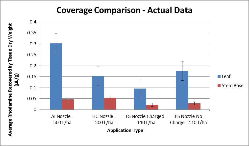
    The following graph shows the coverage observed in µL rhodamine per dry weight of tissue sampled. Bars represent standard error. Each treatment represents three passes (n=3) where each pass included three sub-samples averaged to offset the high variability inherit to spraying. While statistical analysis did not prove significant, there were strong trends. The AI nozzle deposited more dye on the leaves, while the HC and both electrostatic applications were par. Stem coverage achieved in conventional applications was approximately double that of the electrostatic. However, note that the electrostatic system only applied 1/5 of the volume sprayed conventionally.

    When the data is normalized to depict a 500 L/ha application for all treatments, a different story emerges (see below). Now foliar coverage is 25-100% better for electrostatic applications than conventional. Stem coverage is twice that of conventional. Unexpectedly, the uncharged electrostatic treatment outperformed the charged treatment on the leaves. This might be the result of variability in the application, or the result of coronal discharge which can occur when pointy leaves repel charged droplets. This suspicion might be supported by the similar coverage achieved on the stems in both Treatment 3 and 4. You can read more about the Corona Discharge Effect in this article.

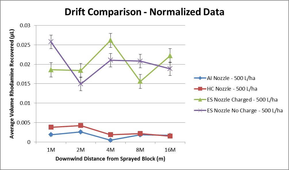
    Regarding drift, we will focus on the normalized data (where all treatments are adjusted to 500 L/ha). An analysis of variance indicated with 95% confidence that the electrostatic treatments drifted significantly more than conventional (approximately 5x more rhodamine detected). Particle drift follows an inverse square rule, where levels decline with distance, but the decline is only minor in all treatments. This may be a function of weather conditions, coupled with the limited distance investigated.

    Winds averaged 6.5 km/h gusting up to 10 km/h at boom height. Temperatures were between 15-17°C and relative humidity at ~70%. These conditions are conducive to drift as droplets are less likely to evaporate and in the case of Very Fine droplets, travel great distances. Many drift studies extend to 300 m from the point of application, whereas we were unable to monitor beyond 16 m. The downward trend would likely have been observed were we able to sample further downwind.

    Observations

    Our data supports the manufacturer’s claim that the electrostatic sprayer has the potential to match the coverage from a conventional application while using 50% less water and pesticide. It is unclear whether the electrostatic charge plays a role in this coverage, or if it is the result of the Very Fine spray quality and air assist (which have been demonstrated to improve canopy penetration). Further, it is unclear whether the charge may actually have been detrimental in the carrot crop. Claims of improved coverage uniformity were not explored in this study, but observations of water-sensitive paper in soybean (see image below) did indicate consistent under-leaf coverage, even at 50% application volume.

    The five-fold increase in drift potential is a significant barrier for this technology. The spray cloud is comprised of like-charged particles that expand in three dimensions, which improves coverage uniformity and penetration into the canopy, but also causes droplets to expand up and out of the canopy. Air assist is used to propel them downward, but the turbulent 9.4 m/s windspeed seemed excessive, even for a dense carrot crop.

    It is possible that focussing and reducing that airspeed may also reduce drift without compromising coverage. Presently, the air shear design of the Ecostatik’s MaxCharge nozzles prevent the operator from reducing the air speed without compromising spray quality. And, even if air speed could be reduced, the spray quality must remain Very Fine to achieve an optimal mass-to-charge ratio, and will therefore always carry an inherently high drift potential.

    Thanks to Kevin Van der Kooi for spraying, and Laura Riches, Tamika Bishop, Terisa Set, Christine Dervaric, Claire Penstone and Aki Shimizu for sample collection. Special thanks to Cora Loucks for assistance with statistical analysis and Martin Brunelle of MS Gregson for providing the Ecostatik for evaluation.

  • Adjuvants in the airblast tank

    Adjuvants in the airblast tank

    Spray adjuvants are tank mix additives that either physically or chemically influence the efficacy, consistency or safety of pesticides. For example, adjuvants can improve the handling characteristics of a spray solution (e.g. water conditioners, de-foamers, emulsifiers). They can improve uptake into a target plant and/or improve the amount of contact between spray droplet and target surface (e.g. non-ionic spreaders). They can also modify droplets to reduce the potential for wastage from drift or run-off (e.g. anti-drift additives, stickers).

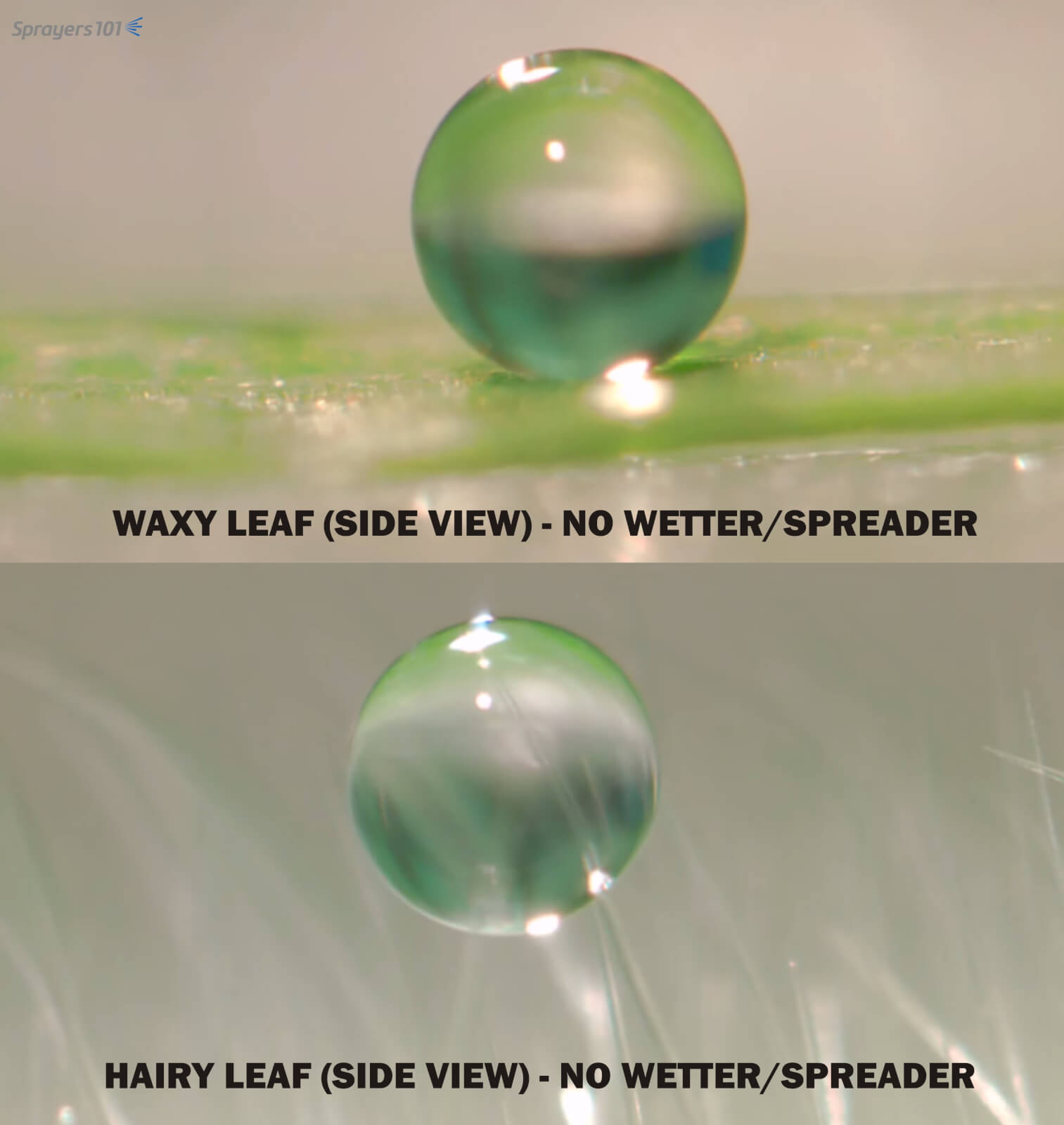
    Note how little of the droplet contacts a waxy leaf (above). This hydrophobic reaction between water and wax can be overcome using a non-ionic spreader. Similarly, note how the droplet gets hung up on the trichomes (hairs) on a leaf before it reaches the leaf surface (below). Again, a non-ionic spreader would reduce droplet surface tension allowing it to splash onto the leaf. Photo Credit – Dr. H. Zhu, Ohio.
    Note how little of the droplet contacts a waxy leaf (above). This hydrophobic reaction between water and wax can be overcome using a non-ionic spreader. Similarly, note how the droplet gets hung up on the trichomes (hairs) on a leaf before it reaches the leaf surface (below). Again, a non-ionic spreader would reduce droplet surface tension allowing it to splash onto the leaf. Photo Credit – Dr. H. Zhu, Ohio.

    Some pesticide labels require the use of adjuvants in the tank mix for the pesticide to work correctly. They are not formulated with the product because of expense, bulk, or product stability, and must be added during loading. In order for a pesticide to work as advertised, it is important to include any adjuvants required by the label. In some cases, we are encouraged to use adjuvants to improve an application, even though they are not on the label.

    There are potential benefits to introducing some unlabelled adjuvants, but there are also potential problems. The difficulty is that unless someone tests a specific tank mix combination for a specific crop, the results cannot easily be predicted. For example, when a tank mix is incompatible, an adjuvant could cause phytotoxicity, create more drift when used with the wrong nozzle, deactivate or enhance a tank partner, and/or potentially reduce spray coverage.

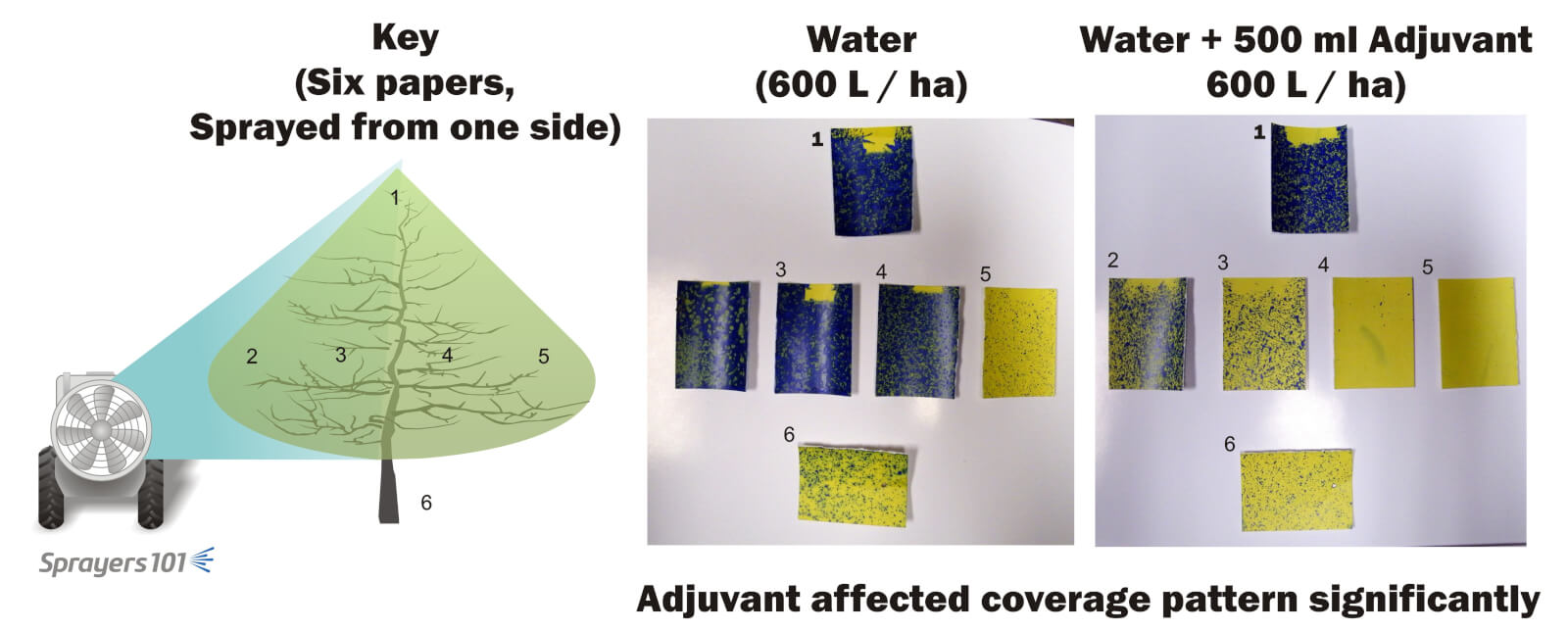
    We once conducted a trial to test a deposition utility modifier intended to reduce run-off and drift. Water-sensitive papers were placed in the canopies of a 40 year old McIntosh orchard, which was then sprayed from one side in late May. The papers in the left panel (dilute control) were sprayed with 600L/ha (~60 g/ac.) of water. Those in the right panel (adjuvant) were also sprayed with 600L/ha but included the label rate of 500 ml of adjuvant. The water-plus-adjuvant reduced drift and runoff, as advertised, but did not penetrate as deeply into the canopy or spread on the papers, which is a concern if the operator was performing alternate-row middle spraying or needed better coverage (e.g. for mites). It was an unexpected side effect.

    For better or worse, even small amounts of adjuvants can have a significant effect on spray coverage. Always test spray coverage when using a new adjuvant in a tank mix.
    For better or worse, even small amounts of adjuvants can have a significant effect on spray coverage. Always test spray coverage when using a new adjuvant in a tank mix.

    We also investigated the use of an anti-drift adjuvant in airblast sprayers, which you can read about here.

    There is no simple answer regarding unlabelled adjuvants; there are too many possible product/adjuvant/plant combinations. If you intend to experiment with an adjuvant, perform a jar test to test for physical incompatibility. Then spray a small volume of the tank mix on a few trial plants to ensure there are no unexpected chemical issues (e.g. phytotoxicity or inactivating tank mix partners) or coverage issues.

    It is highly recommended that every sprayer operator have a copy of Purdue Extensions’ 2015 “Adjuvants and the Power of the Spray Droplet – PPP-107”. This comprehensive handbook describes of how water quality and adjuvants affect the performance of pesticide applications. I consult it regularly.

    Here are two videos from Dr. H. Zhu, USDA-ARS Ohio, showing how adjuvants that affect surface tension can help improve the level of contact between spray droplet and target surface.