This article was co-authored by Kristy Grigg-McGuffin, OMAFA Horticulture IPM Specialist
In view of the frequent heavy rains in many regions this season, understanding rainfastness, or the ability of a pesticide to withstand rainfall, is important to ensure proper efficacy. All pesticides require a certain amount of drying time between application and a rain event. Typically, residue loss by wash-off is greatest when rain occurs within 24 hours of spraying. After this point, the rainfastness of a product will depend on formulation, adjuvants and length of time since application.
Rainfastness of Insecticides
John Wise, Michigan State University has studied rainfastness of common tree fruit insecticide groups and his findings are summarized below. For the complete article, refer here. Note that some products listed in this article may not be registered for use in Canada. Check with your local supplier or in Ontario, refer to OMAFA Publication 360 for a complete list of registered products.
According to Wise, the impact of rain on an insecticide’s performance can be influenced by the following:
1- Penetration
Penetration into plant tissue is generally expected to enhance rainfastness.
- Organophosphates have limited penetrative
potential, and thus considered primarily surface materials. - Carbamates and pyrethroids penetrate the cuticle,
providing some resistance to wash-off. - Spinosyns, diamides, avermectins and some insect
growth regulators (IGR) readily penetrate the cuticle and move translaminar (top
to bottom) in the leaf tissue. - Neonicotinoids are considered systemic or
locally systemic, moving translaminar as
well as through the vascular system to the growing tips of leaves (acropetal
movement). - For products that are systemic or translaminar,
portions of the active ingredient move into and within the plant tissue, but
there is always a portion remaining on the surface or bound to the waxy cuticle
that is susceptible to wash-off.
2- Environmental persistence and inherent toxicity
Environmental persistence and inherent toxicity to the target pest can compensate for wash-off and delay the need for immediate re-application.
- Organophosphates are highly susceptible to
wash-off, but are highly toxic to most target pests, which means re-application
can be delayed. - Carbamates and IGRs are moderately susceptible
to wash-off, and vary widely in toxicity to target pests. - Neonicotinoids are moderately susceptible to
wash-off, with residues that have moved systemically into tissue being highly
rainfast, and surface residues less so. - Spinosyns, diamides, avermectins and pyrethroids
are moderate to highly rainfast.
3- Drying time
Drying time can significantly influence rainfastness, especially when plant penetration is important. For instance, while 2 to 6 hours is sufficient drying time for many insecticides, neonicotinoids require up to 24 hours for optimal penetration prior to a rain event.
4- Adjuvants
Spray adjuvants that aid in the retention, penetration or spread will enhance the performance of an insecticide.
The following tables can serve as a guide for general rainfastness to compliment a comprehensive pest management decision-making process. They are adapted from “Rainfast characteristics of insecticides on fruit” by John Wise, Michigan State University Extension.

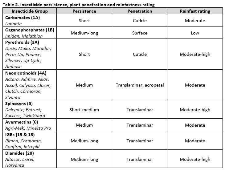
Based on simulated rainfall studies to combine rainfastness with residual performance after field-aging of various insecticides, including carbamates (Lannate), organophosphates (Imidan, Malathion), pyrethroids (Capture), neonicotinoids (Assail, Actara, Admire), IGRs (Rimon, Intrepid), spinosyns (Delegate) and diamides (Altacor), Wise recommends the following re-application decisions for apples. Additional work was done on grapes and blueberries; see Wise’s article for this information. Among the crops, variation in rainfastness of a specific insecticide occurs since the fruit and leaves of each crop have unique attributes that influence the binding affinity and penetrative potential.
- ½ inch (1.25
cm) rainfall: All products with 1-day old residues could withstand ½ inch
of rain. However, if the residues have aged 7 days, immediate re-application
would be needed for all products but Assail, Rimon, Delegate or Altacor on
apples. - 1-inch (2.5
cm) rainfall: In general, most products would need re-application following
a 1-inch rainfall with 7-day old residues, whereas Delegate and Altacor could
withstand this amount of rain on apples and would not need to be immediately
re-applied. Some products such as Imidan on apples could withstand 1 inch of
rain with 1-day old residues. - 2-inch (5
cm) rainfall: For all products, 2 inches of rain will remove enough
insecticide to make immediate re-application necessary.
It is important to note, not all products registered for the selected pests were included in this study. Refer to Publication 360 for a complete list of management options.
Rainfastness of Fungicides
There is no comparable research on rainfastness of fungicides and few labels provide this kind of information. A general rule of thumb often used is that 1 inch (2.5 cm) of rain removes approximately 50% of protectant fungicide residue and over 2 inches (5 cm) of rain will remove most of the residue. However, many newer formulations or with the addition of spreader-stickers, some products may be more resistant to wash-off. Avoid putting on fungicides within several hours before a rainstorm as much can be lost to wash-off regardless of formulation. As well, there are exceptions to the general rule in regard to truly systemic fungicides such as Aliette and Phostrol.
The effectiveness of sticker-spreaders with fungicides is variable and product/crop specific. Penetrating agents don’t help strobilurins; in fact, some fungicide/crop combinations have been associated with minor phytotoxicity due to excessive uptake. Captan, which is intended to stay on the surface, is notorious for causing injury when mixed with oils or some penetrating surfactants that cause them to penetrate the waxy cuticle. Consult labels for minimum drying times for individual products and recommendations for using surfactants.
Annemiek Schilder, Michigan State University suggests the following to improve fungicide efficacy during wet weather:
- During rainy periods, systemic fungicides tend
to perform better than protectant (or contact) fungicides since they are less prone
to wash-off. - Applying a higher labelled rate can extend the
residual period. - Apply protectant fungicides such as captan
(Supra Captan, Maestro), mancozeb (Manzate, Dithane, Penncozeb) and metiram
(Polyram) during sunny, dry conditions to allow for quick drying on the leaves.
These types of fungicides are better absorbed and become rainfast over several
days after application. - Apply systemic fungicides such as sterol
inhibitors (Nova, Fullback, Inspire Super), SDHI (Fontelis, Sercadis, Kenja, Aprovia
Top, Luna Tranquility) and strobilurins (Flint, Sovran, Pristine) under humid,
cloudy conditions. The leaf cuticle will be swollen, allowing quicker
absorption. In dry, hot conditions, the cuticle can become flattened and less
permeable, so product can breakdown in sunlight, heat or microbial activity or
be washed off by rain.
Click here to refer to the complete article.