Use this spreadsheet to calculate the minimum boom heights needed for various applications.
Some caution:
The values are theoretical and assume the fan angles are accurate. Some nozzles don’t produce the advertised fan angle. Enter your actual angle in the spreadsheet
The theory assumes that the droplets at the edge of the fan always move in their projected direction. In fact, after some distance (say 50 to 75 cm, gravity pulls the droplets down and the pattern no longer widens at the same rate. The rate of pattern collapse depends on the droplet sizes.
Use the 0% overlap column to help with banding nozzle pattern width. Simply use the nozzle spacing column to enter your desired band width.
Note that angling the nozzles forward or backward decreases your minimum boom height, but depending on the deflection of the spray in the wind, this too has limits.
Too high a boom obviously increases drift. But patternation from overlap isn’t affected that much, largely because the pattern is now subject to aerodynamics.
Humidity is important in spraying. With the average tank of pesticide being 90 to 99.5% water, evaporation plays an important role in both droplet size and active ingredient concentration. Low humidity causes droplets to evaporate faster, potentially increasing drift and reducing uptake. But relative humidity (RH) isn’t the best way to measure this effect because the same RH at two different temperatures results in two different water evaporation rates.
Instead, we present Delta T, also known as “wet bulb depression”. Delta T is an atmospheric moisture parameter whose use in spraying has made its way to North America from Australian operations. It is defined as the dry bulb temperature minus the wet bulb temperature, and provides a better indication of water evaporation rate than RH. Higher Delta T means faster water evaporation.
The recommendations from Australia are to avoid spraying when the Delta T is either too high or too low, with a range of two to eight being described as ideal.
Figure 1: Delta T chart used in Australia (Source: Australian Gov’t Dept of Meteorology)
Delta T is being reported on an increasing number of weather stations, and it’s time we took a closer look at what it means.
Measuring Relative Humidity
In the early days of weather reporting, relative humidity was calculated from psychrometric charts. All one needed was a hygrometer, usually a sling psychrometer. A sling psychrometer is two identical thermometers side by side whose bulbs could be slung in a circle, exposing them to moving air. One bulb was covered in a cotton wick moistened with distilled water, the other was left exposed and dry.
As the bulbs met moving air, water evaporated from the cotton wick and that reduced the temperature of that thermometer. The dryer the air, the greater the evaporation rate and therefore the greater the temperature drop. The dry thermometer was unaffected by this movement.
On measuring the wet and dry bulb temperature, one consulted a psychrometric chart. This chart converted the two temperatures to total water content in the air, compared it to total water-holding capacity, and expressed it as Relative Humidity. Psychrometric charts are useful for many other air parameters such as dew point, vapour pressure, or enthalpy. (Pause briefly to give thanks that we don’t need to know what enthalpy is.)
Turns out that RH is a poor measure of water evaporation rate. An RH of 24% at 20 C has exactly the same evaporation rate as an RH of 44% at 35 C. That’s why Delta T is the preferred measurement: it’s linearly related to evaporation.
Note: Modern electronic weather stations don’t need two thermometers to measure air moisture content, and use polymers whose capacitance or resistance changes with atmospheric moisture. Add an internal look-up table, and we have all the information we need.
Pros and Cons of Water Evaporation
It’s important to note that our Australian colleagues caution against spraying when water evaporation rate is both too high and too low.
Too High:
Water evaporates rapidly, reducing droplet size and pre-disposing the smaller droplets to drift;
Deposited droplets dry quickly, reducing pesticide uptake which is more effective from a wet deposit.
Too Low:
Water doesn’t evaporate, maintaining the smaller droplets in a liquid state. These small droplets are already drift prone, but are now more potent because of more effective uptake. Overnight conditions that are inverted are usually humid, adding to harm potential from the inversion.
Delta T in North America
The addition of this parameter to our spraying weather lexicon has been useful. But it’s important to understand the context in which it was developed to properly judge its suitability.
Aussies started talking about Delta T because the use of finer sprays under the hot dry conditions found during their summer sprays resulted in significant evaporative losses, significantly greater drift potential, and potential reduction of product performance. The guidelines to avoid spraying when Delta T exceeds eight or ten originate there.
A few changes have happened since these guidelines were developed. Over the past ten to 20 years, we’ve observed greater use of low-drift sprays, with the coarser sprays’ larger droplets resisting fast evaporation. In the past five to ten years, water volumes have increased due to our heavier reliance on fungicides, desiccants, and contact modes of action. Both of these developments have helped reduce the impact of a dry atmosphere. We simply can’t say if a Delta T of 10 is too high with these new application methods.
Looking at it another way, if Delta T values are very high, increasing water volume and droplet size will mitigate that to some degree, as the Aussies state in their extension materials (linked earlier).
Formulation
Pesticide formulation can also play a role in evaporation. Once the water is gone, oily formulations may still have good uptake because the oily active ingredient stays dissolved in the oily solvents. This is both good and bad, helping on-target efficacy but also increasing the risk of more potent drift. Solutions, on the other hand, are more likely to leave their actives stranded on leaves as crystals once the water is gone.
Bottom Line
Delta T is definitely useful information when spraying. It will typically rise and fall with air temperature as the day proceeds, and it is wise to consider suspending operations when values are critical. Take note of the Delta T when spraying the same product throughout these hot days and learn from the experience. Remember, the atmosphere affects not just sprays but also plants and insects, and due to this complexity we may not be able to attribute success or failure to just one measurement.
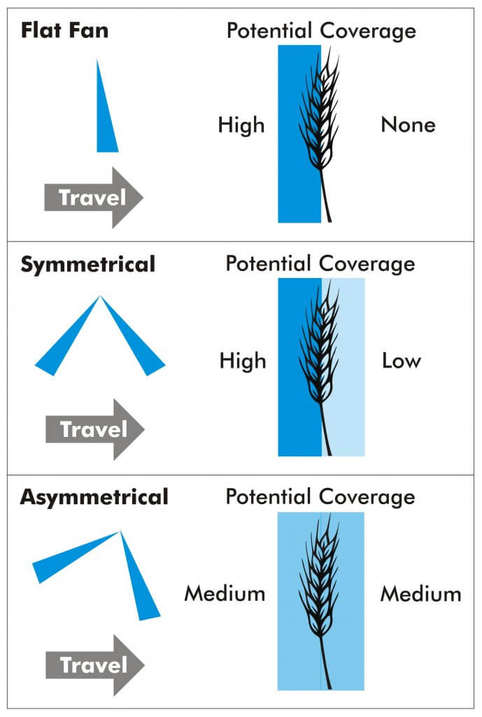
Well, first, understand they are intended for vertical targets, like wheat heads. Here’s a diagram of how they are (ideally) supposed to work:
Here’s is the ideal coverage from fan nozzles on a vertical target. Note that high booms, smaller droplet sizes, high travel speeds, high or changeable wind conditions and uneven emergence can negatively affect coverage.
Here’s our very own Dr. Tom Wolf to tell you all about them.
Now understand they don’t seem improve matters (at conventional pressures) in broad leaf crops. We compared spray coverage from several nozzles in soybean. The lack of any clear cut winner was disheartening, but even messy results can lead to valuable conclusions! Read more about the experiment here and watch the video below:
And finally, understand that choosing a brand or variation of a dual fan nozzle arrangement is likely the least important factor. It falls, in our opinion, last in this sequence of factors:
Spray timing (i.e. crop stage, pest stage)
Product choice
Boom height (Keep ’em low)
Droplet size (Keep ’em Coarse or larger)
Spray volume (Go with more gallons per acre, not less)
ExactApply
is an application system capable of PWM, introduced by John Deere in August,
2017, with its first customer field season in 2018. ExactApply offers several
unique features that differentiate it from the existing systems. Here is a
brief description of its major components and capabilities:
Nozzle
Body Design:
The body contains a turret with six numbered nozzle locations, all pointed down, and two solenoids, one on either side of the body. Three nozzle locations are on short feeds (locations 1, 2, and 3), whereas the remainder are on long feeds (4, 5, and 6). The front locations and left solenoid is called “A”, whereas the right solenoid and rear location is “B”.
ExactyApply nozzle body
Nozzles are paired so that A or B or both are capable of spraying at a time, depending on the selected mode. Pairs are 1 & 4, 2 & 5, and 3 & 6. The operator manually rotates the desired nozzle pair into position.
When a short feed (1, 2, or 3) is placed at the front of the body, the system is in Separated Mode. In this mode, the left solenoid controls the front nozzle and the right solenoid control the rear nozzle. Either or both can be used, in pulsing (PWM) or conventional mode, selected through the monitor.
When a long feed (4, 5, or 6) is placed at the front, the body is in Combined Mode. Now, all flow from the right and left solenoid can only exit the front nozzle. Very high flows are achievable in Combined Mode, making it suitable for liquid fertilizer application. It may not have other practical applications in Western Canada.
View from left side of body (solenoids removed). Turret position #4 (tall feed) is in front, and #1 (short feed) is in back, placing the body in Combined Mode.
In Pulsing Mode, each solenoid pulses at 15 Hz, meaning it completes 15 open-and-close-cycles per second. The A and B solenoid timing is offset by 180 degrees, so that the B nozzle is in the middle of its on-cycle when the A nozzle is in the middle of its off cycle. In combined mode, this means that the system operates at 30 Hz.
Adjacent bodies are also 180 degrees out of sync with each other, similar to Capstan, Raven, and TeeJet bodies, so that whenever a nozzle is off, its adjacent partners are on (when operating at 50% DC and above). Another way of saying this is that all even-numbered bodies act together, and all odd-numbered bodies act together but half a cycle later. This results in a blended pulse that prevents skips.
Plunger assembly inside solenoid. Black plastic portion can be removed, exposing poppet and spring.
The proportion of each cycle that the solenoids are open is known as the duty cycle (DC). At 100% DC, the valves are always open. At 50% DC, the valves are open 50% of the time. The minimum DC allowed by the system in default is 25%. This can be lowered to a smaller value within the monitor.
Opened plunger assembly showing tip of poppet (right) and seat (left)Poppet inside plunger assembly is pulled back by magnet inside solenoid 15 times per second
DC is closely related to the flow rate of the nozzle. There are two ways of looking at this. An 08 sized tip operating at 40 psi will have a flow rate of 0.8 US gpm at 100% DC, about 0.4 US gpm at 50% DC, and close to 0.2 US gpm at 25% DC. This feature is primarily useful when sprayer speed is changed, requiring new flow rates without a change in spray pressure.
Pulsing Mode is not available for nozzles sized smaller than 02, or for air-induced tips.
Pulsing can be disabled to allow the use of air-induced or other tip technologies that may not function well when pulsed. This is called AutoSelect Mode.
AutoSelect
Mode:
AutoSelect Mode (“Auto Mode” in 4600 monitor) can be used to achieve three unique flow rates. “A” alone, “B” alone, or “A” & “B”. When properly staggered, a travel speed range similar to Pulsing Mode can be achieved, although pressure will rise within each nozzle as travel speeds increase, as in a conventional system.
In AutoSelect Mode, the user selects a tip for position A, and an incrementally larger tip for position B. The monitor requires that the user inputs minimum and maximum pressures for A, B, and A&B. Travels speeds corresponding to these tip and pressure choices are calculated, and the monitor warns the user when speeds don’t overlap. The user either changes minimum and maximum spray pressures, or selects a different sized tip to eliminate the gap.
AutoSelect Mode is useful when a certain specific tip is required which is not compatible with Pulsing Mode, for example drift protection with air-induced tips.
Pulsing
Mode Nozzle Selection
At this time, John Deere nozzles best suited to the ExactApply’s Pulsing Mode are the LDM, LD, LDX, and 3D. Of these, the LDM most closely represents the spray quality of the LDA and ULD that John Deere operators are accustomed to. The remainder are considerably finer.
ASABE spray qualities for Low-Drift Max (LDM) tips. Being Very Coarse at lower pressures, applicators are advised to use higher spray pressures (50 to 70 psi) when coverage is important.ASABE spray qualities for Guardian (LDX) tips. Note that the smaller sizes (03, 04, 05) produce finer sprays and will require pressures below 40 psi to have any reasonable drift reduction. ASABE spray qualities for 3D tips. As with LDX, the smaller sizes (03, 04, 05) produce finer sprays and will require pressures below 30 psi to have any reasonable drift reduction. Such low pressures may narrow the spray pattern. ASABE spray qualities for Low-Drift (LD) tips. As with LDX, the smaller sizes (03, 04) produce finer sprays and will require pressures below 40 psi to have any reasonable drift reduction.ASABE spray qualities for the Low-Drift Twin (LDT). Comprised of two same-sized LD tips assembled in a TwinCap.
Proper sizing for PWM requires that tips be sized for about 20 to 40% extra capacity. In other words, at expected average travel speeds, the pulsing duty cycle should be approximately 60 to 80%. The following chart has a highlighted column at 70% duty cycle for that reason. Assuming an ExactApply operator expects to apply 5 gpa and travel at 15 mph on average, possible nozzle options (highlighted in yellow) are:
03 at 60
psi
04 at 30
psi
05 at 20
psi
06 at 15
psi
Calibration chart for PWM systems. Nozzles are sized at about 70% Duty Cycle (grey column). Options for 5 gpa at 15 mph are highlighted yellow. Black highlights represent speeds >25 mph, not available.
The best
choice will likely be either of the first two options, as the third and fourth
have spray pressures which are probably too low for good nozzle performance.
The decision would depend on the spray quality obtained for each of the
remaining two options.
Of
course, spray pressure can be altered to suit the operator’s spray quality
requirements. This merely affects the available speed range as well as the DC
at which the system operates at a given target speed, possibly affecting
Pulsing Mode utility.
The row of speeds adjacent to the selected nozzle and pressure identifies the approximate travel speed range that can be expected, from 25 to 100% DC.
It’s important to know your current DC to be sure the system is operating properly, and also to take full advantage of turn compensation features. We’ve described a way to place a DC display module on your home screen here.
The application volume can be changed to suit the specific use, the chart’s speed values are updated automatically. Make sure the nozzle spacing at the top left is correct for your sprayer
Pressure
Drop across Solenoids
PWM
solenoids represent a restriction to flow, and may cause a pressure drop. John
Deere has published the pressure drop, and it is shown in the above chart
(download version only). The pressure drop is fairly low, only 2 psi for an 04
tip operating in separated mode at 40 psi. For an 06 tip, the drop is 3 psi,
and for an 08, it’s 6 psi. a #10 tip has a 10 psi drop at 40 psi. These
pressure drops must be added to the operating pressure of the sprayer. Pressure
drop is important because the LDX, LD, and 3D tips will be operated at low
pressures to obtain coarse sprays for drift protection. Operating an 08 tip at
20 psi (at which pressure it has s drop of 3 psi) will result in in a tip
pressure of 17 psi. Since we are at the low end of a nozzle’s operating range,
pattern stability may be compromised when the drop is not taken into account.
Why 70%
Duty Cycle?
An operator of any PWM system needs to know their current duty cycle. On ExactApply, a module can be installed on the home screen that provides a visual display. We show how to do this here.
There are
five main reasons a nozzle should be sized to run at approximately 70% DC. The
first is to provide speed flexibility. An operator may need to speed up somewhat,
but usually not more than 30%. On the other hand, slowing down is much more
common to accommodate challenging terrain, and a factor of two to three is
possible (from 70% DC to 25% DC).
Secondly,
drift reduction through lower spray pressure usually requires less speed due to
the associated lower flow rate. With some DC room to spare, the loss of flow
can be corrected without requiring a speed change.
Thirdly,
spot spraying at a slightly higher rate is possible, again through DC alone.
Fourth,
Nozzle Rate Boost of up to 25% for up to six nozzle locations is possible
within the monitor, but only if the system is operating at 75% DC or less.
Finally,
turn compensation, during which the outside boom travels faster than the
tractor unit and the inside boom slower, requires this additional capacity.
More on turn compensation here.
AutoSelect
Mode Nozzle Selection
AutoSelect
Mode allows for three flow rates to be used in succession: A, then B, the AB.
The key to success is to use small size increments between A and B, and to use
tips that have a wide pressure range.
In the
example below, the A location was an 02 tip and the B was an 03, for a total of
05. Pressure was not allowed to drop below 30 psi to retain good patterns.
Pressure at switch over to the next largest flow rate therefore needed to be 80
psi to make the moves possible without pressure gaps resulting in
over-application. As a result, the spray quality can be expected to fluctuate
three times as the sprayer accelerates through A, B, and AB in succession.
Nozzle
selection should seek to emphasize the middle of the pressure range of either B
or AB to avoid unnecessary fluctuations.
Spray pressure and travel speed as Auto Mode moves through A, then B, then both A&B
Download an Excel sheet that assists in nozzle selection for Auto Mode here.
A
maintenance kit comes with each ExactApply sprayer. It contains two spare
plunger assemblies, clips, and pins, as well as a brush, an O-ring picker, and
a torque driver.
Maintenance kit
The
ExactApply body is fairly easy to take apart for servicing. Hair pins at the
back of the unit secure each solenoid, and both pull out easily. The plunger
assembly can be disassembled without tools. Take care not to drop the poppet
spring!
Reassembly
of the plunger requires the use of the torque driver fitted with a 17 mm
socket, included in the kit. Do not over-tighten the plastic component.
Aside
from the manual rotation of the turret to select a different nozzle
combination, the only moving part in the ExactApply body is the poppet in the
plunger assembly. This piece is the valve that controls flow rate, and opens
and closes 15 times per second whenever pulsing mode is on, moving like a
piston in a cylinder. Debris (sand, fertilizer crystals, etc.) can interfere
with the seal of the poppet against its seat, and good filtration is important.
In the first generation, metal flakes began appearing inside some plunger assemblies . A coating de-laminates off the sleeve and can cause the plunger to stick. This has been starting at 800 h of use. The springs have also been observed to break. This problem has been addressed in newer generations.
Metal flakes interfering with plunger actionPlunger damage showing likely source of metal flakesBroken plunger spring
Certain formulations may build up a residue that interferes with poppet movement. It’s impossible to predict all possible formulation impacts, but oily formulations such as emulsifiable concentrates (EC, milky appearance) are likely to be more problematic than solutions (S, clear appearance). John Deere recommends a daily rinse of the boom through both the A and B valves with Erase, a tank cleaner product. Fortunately, the R series sprayer allow for boom flushes from the clean water tank even when the product tank has product in it.
Each nozzle body contains ten O-rings and two sets of seals. The turret assembly has two large rings, and each plunger assembly has four. Care needs to be taken to prevent damage to these rings to prevent leaks.
O-rings in nozzle body
Some
Recommendations
The
ExactApply system is very full featured and customers new to PWM can be
overwhelmed by the number of choices at their disposal. Let’s simplify the
system and make some basic recommendations.
Pulsing mode is likely to be the most useful feature of the system. Plan to use this feature for most spraying operations.
In Pulsing mode, select from John Deere’s LDM, LDX, LD, and 3D tips. The LDX, LD, and 3D offer similar Medium spray qualities and should be operated between 20 and 40 psi to produce lower-drift sprays. Check spray patterns at these pressures and ensure that 100% overlap is achieved (pattern width is twice nozzle spacing).
The LDM (Low Drift Max) is coarser than the above nozzles (comparable to ULD or LDA) and is available in 03, 04, 05, 06, 08, and 10 sizes. This will be the tip of choice for pulsing mode and can be used at higher pressures to ensure good pattern formation.
Separated mode can handle most flow rates, and offers the flexibility of choosing A (front tip) or B (rear tip) or both. This means turret 1, 2, or 3 will be in the forward (A) location.
Equip the A location with your low volume tip (say, 5 gpa). Place the high volume tip (say 10 gpa) at the B location. Use both together for late season sprays into dense canopies (in this case, A&B=15 gpa)
Twin tips for Fusarium Head Blight (FHB) can be achieved in five different ways.
3D tips in “A” or “B”, alternating their orientation along the boom (forward, backward, forward…). Pulsing Mode. (Since these tips are not very coarse, low pressures are needed to ensure that the angle of the spray persists more than a few inches).
3D tips in “A” and “B” on each body, front facing forward, rear facing backward, and operating in A&B. Pulsing Mode.
LDT (Low Drift Twin) in “A” or “B”. LDT is a TwinCap with two LD tips installed. Pulsing Mode.
LDM (Low Drift Max) in installed in a TwinCap in “A” or “B”. These are coarser sprays that will retain their direction longer and are well suited for FHB. Pulsing Mode.
GAT (GuardianAIR Twin), an air-induced tip, running in either conventional “A” mode or in Auto Mode but sized for “B” (avoid operating in A&B to prevent pattern interference).
Some recent recommendations: A customer wanted tips for 5, 10, and 15 gpa at 14 mph, and the 15 gpa was for FHB. He didn’t want to be too coarse. We recommended the LDM 03 at 60 psi (5 gpa) in “B”, the 3D 08 at 30 psi (10 gpa) in “A”, and both together, with the 3D facing forward, for FHB for 15 gpa. The sprays would be “Coarse”, a nice middle ground.
ExactApply joins Capstan PinPoint II, Raven Hawkeye, and WEEDit Quadro, Agrifact StrictSprayPlus, and TeeJet DynaJet with PWM capable systems. Auto Mode is a version of nozzle switching first introduced into the market as Arag Seletron and Hypro DuoReact. It appears to be a full-featured system that is fully integrated into the new John Deere 4600 display but is also available as a retrofit on the older R-Series 2630-equipped sprayers.
Need to find the right nozzle size for your application? Sometimes a simple chart is the easiest way to figure things out. Print it and place it in your sprayer cab.
In this chart, identify your water volume along the top row, and follow the column until you encounter the travel speeds you’re interested in.
Once you’ve encountered your travel speed, move along the row to the left to identify the nozzle size and spray pressure.
Make sure that your travel speeds are achieved at a pressure that’s right for the nozzle you’re using. For most air-induced nozzles, this will be about 60 to 70 psi (highlighted).
Once you’ve decided on a nozzle size, the travel speed column for that size becomes the travel speed range at various pressures. Avoid operating a low-drift spray below 30 psi – its pattern will be too narrow and likely its spray quality will be too coarse for good results.
Click on the images or text below to download a high quality pdf version of each chart, starting from the top with US, 15″ spacing, then US, 20″, then US 30″, then metric, 50 cm. Print, laminate, and place them in your sprayer cab.