Category: Nozzles & Droplets

Articles helping with field sprayer nozzle selection

  • Validate Airblast Output – Nozzle Calibration

    Validate Airblast Output – Nozzle Calibration

    Sprayer math is important. It ensures the operator applies the correct product rate and has enough to complete the job. But, it assumes the airblast sprayer is behaving as expected… and it often doesn’t. After confirming the airblast travel speed, use one of the following methods to assess sprayer output. There are pros and cons to each.

    The area method

    Operators that claim the sprayer empties in the same place every time assume everything’s alright. They are performing a variation on the area method.

    Essentially, you fill the sprayer with enough water to spray one hectare (or acre) and then spray that area. If the tank empties where expected, you know your output rate (i.e. volume / area). But, there are a few problems with this method:

    • Most operators don’t have an accurate test area marked off, and even when they think they know the area, measurements prove otherwise. They’re always amazed when this happens.
    • The area method has poor resolution. It reveals the total output but does not assess individual nozzles. For example, partially-blocked nozzles and worn nozzles average out (we’ve seen it). Rate controllers provide whatever pressure is required to match the desired output, masking individual nozzle problems.

    The dip stick method

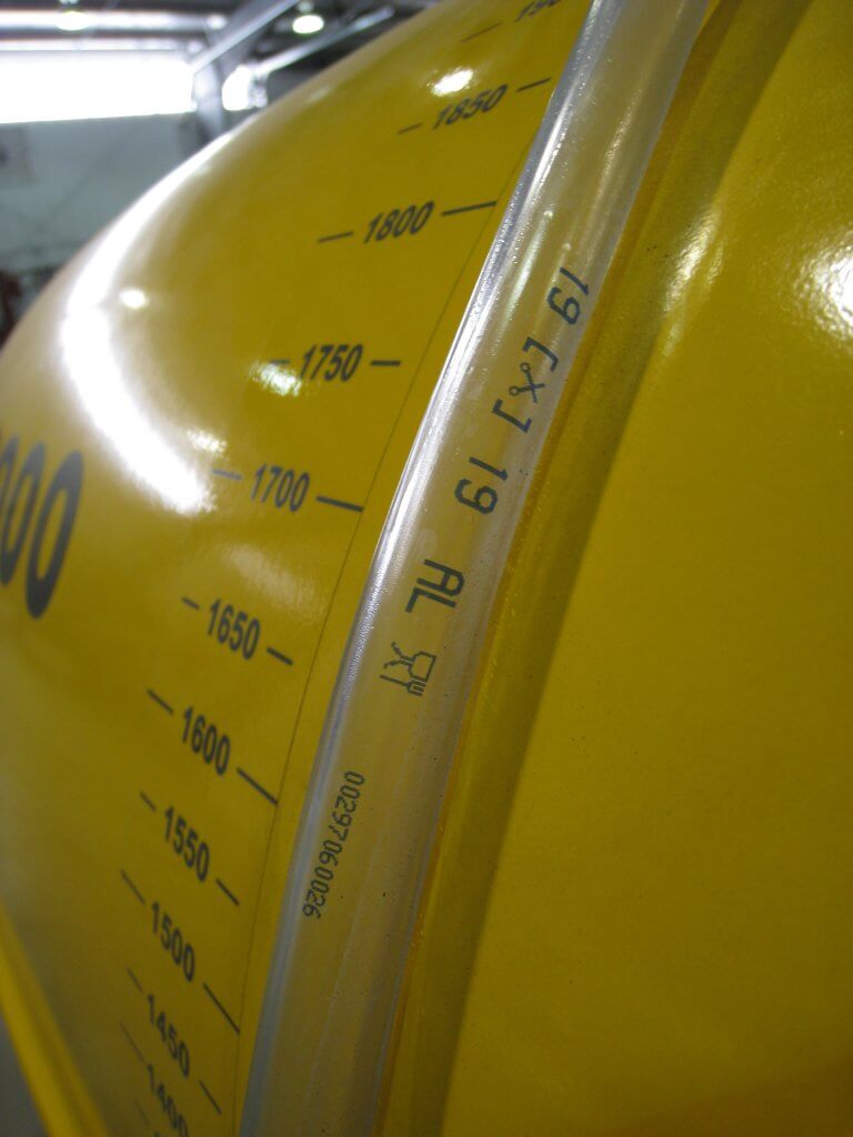
    Another method is to fill the sprayer to a known volume using a flow meter, while observing a sight level or a graduated dip stick. Then, while parked, the operator sprays for a given amount of time and determines the difference in the volume remaining in the tank.

    This method can be defeated if volume is misread. It’s an easy error to make if the sprayer is parked on a grade, or the dipstick shifts in a tank with a rounded bottom. And, of course, it also masks individual nozzle problems.

    Sight levels can be misleading when the sprayer is parked on a grade. They are often opaque and hard to read.

    The timed output method

    The preferred method is to measure the output of each nozzle individually. We performed a review on several timed output methods here. It can be messy and time consuming, but it’s accurate. Appropriate personal protective equipment is required to perform the timed output method – expect to get wet.

    1. Fill the rinsed sprayer half-full with clean water and park it on a level surface.

    2. With the fan(s) off, bring the sprayer up to operating pressure. Start spraying with all nozzles open (closing any will change the pressure).

    3. You will need 1 meter (3 feet) of 2.5 cm (1″) diameter braided hose (have a second, longer hose to reach the top of a tower sprayer). It should be stiff enough that you can slip it over a nozzle body while holding the other end. Use it to guide flow into a collection vessel, held with your other hand. The hose not only reaches the top nozzle on towers, but it lets foam dissipate before it gets to the vessel.

    4. When the flow from the hose is steady, direct it into the collection vessel for 30 seconds (a partner with a stopwatch is very helpful). It is preferable to collect for a minute because it improves the accuracy.

    5. Determine and record the nozzle output per minute. Graduations on plastic collection vessels are unreliable. It’s preferable to weigh the output on a cheap, digital kitchen scale. One milliliter of clean water weighs one gram. Don’t forget to subtract the weight of the vessel (this is called taring) and double the output if you only collected for 30 seconds.

    Interpreting the results

    Once you have recorded all the outputs, you will have to convert the output to U.S. gallons or liters per minute, depending on units in the nozzle manufacturer’s catalogue (see common conversions below).

    Replace any nozzles that are 10% (or preferably 5%) more or less than the rated output. This not only indicates a rate problem, but likely a problem with droplet size as well. If enough nozzles are worn, consider replacing all of them. Nozzles should go on as a set, and come off as a set (unless replacing a broken tip, of course). This can be an expensive proposition for large airblast sprayers, but it is part of operational costs.

    Don’t assume new nozzles are accurate. We’ve found +/- 5% flow variation right off the shelf. Keep your receipts.

    Testing and replacing nozzles is an important part of sprayer operation, no matter how many there are. This Air-O-Fan is nozzled for Australian almonds.

    Helpful conversions

    Anyone that has tried the timed output method in Canada knows the pain of our Metric-esque (Mocktric?) units. We’re an odd hybrid because our label rates are in metric, but our nozzles and many of our sprayers are US Imperial. You can find a complete collection of conversion tables here, but the most common calculations are reproduced below:

    If collecting in ounces, converting to U.S. Gallons per minute:

    us-gallons-per-minute

    If collecting in millilitres or grams converting to U.S. Gallons per minute:

    us-gallons-per-minute

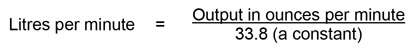
    If collecting in ounces, converting to litres per minute:

    liters-per-minute

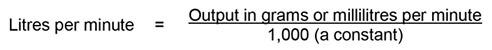
    If collecting in millilitres or grams converting to litres per minute:

    liters-per-minute

    If collecting in ounces, converting to Imperial gallons per minute:

    imperial-gallons-per-minute

    If collecting in millilitres or grams converting to Imperial gallons per minute:

    imperial-gallons-per-minute

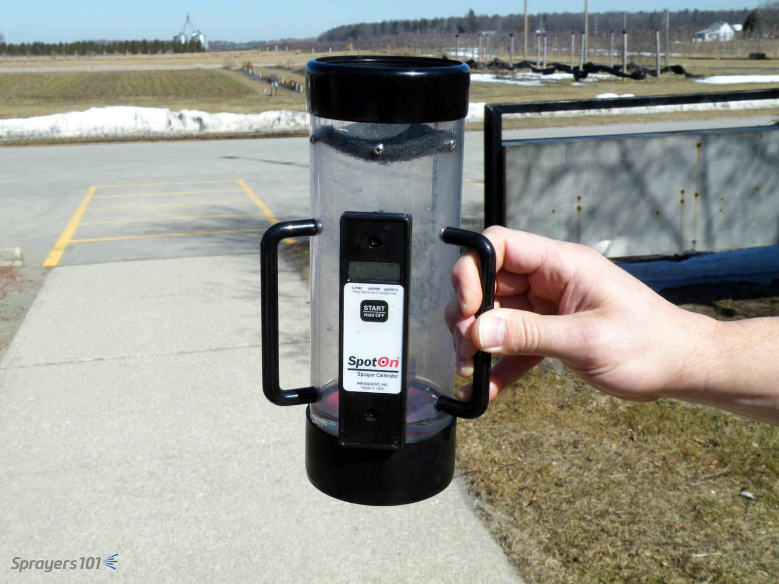
    A more sophisticated option

    The timed output method is slow and requires math. You can avoid both problems by using electronic calibration vessels like the Innoquest SpotOn SC-4. We’ve tested both, and they are as accurate as weighing the output – but much faster.

    They can, however, be fooled by foam. We’ve had good results using a length of braided hose to direct the flow and dissipate most of the foam. Typically, foaming means the sprayer wasn’t rinsed enough.

    The SpotOn SC-4 calibration vessel is much easier, faster and more accurate than the classic pitcher-and-stopwatch approach to timed output tests.
    The SpotOn calibration vessel is easier, faster and more accurate than the classic pitcher-and-stopwatch approach to timed output tests. The SC-4 (pictured) is for airblast and SC-1 is for field sprayers.

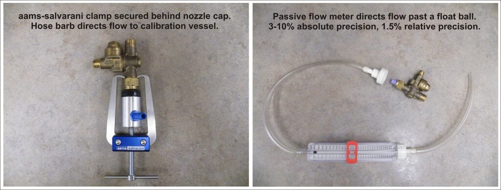
    Another approach is to hose-clamp multiple hoses over nozzle bodies and spray all at once. This is tricky and takes time. Plus, if you suffocate the nozzle’s exit orifice (creating back pressure) or block the air inlets on AI nozzles, you will get a false reading.

    Be careful not to plug air inlets on air induction nozzles – you may get a false reading.

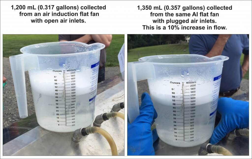
    We prefer nozzle clamps over hose clamps (see the AAMS-Salvarani nozzle clamp pictured below). There are pincers designed to latch behind the nut of the nozzle body, but compatibility can sometimes be an issue (e.g. with Turbomist sprayers).

    Passive flow meters (also pictured below) remove the need for a collection vessel, but they’re a better fit for field sprayers since they have to be held in place manually. They are difficult to source in North America because their accuracy is questionable, but they are fine for comparing relative flow from tip to tip.

    Nozzle clamp or flow meter, avoid suffocating the nozzle exit orifice or AI nozzle air inlets.

    2016_nozzle_flow_meters
    Left: Nozzle body hose clamp. Right: Passive flow meter.

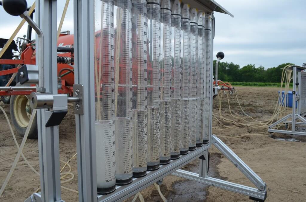
    Some grower groups, or professional consultants, spring for very sophisticated and accurate units, such as AAMS-Salvarani flow measurement system pictured below.

    AAMS-Salvarani flow measurement system. We used these on a pumpkin sprayer in New Hampshire, but they work with airblast too.

    No matter your preferred method, take the time to confirm your sprayer output at the beginning of the season and whenever you make repairs or significant changes to your sprayer.

  • What’s with dew? – Tips with Tom #9

    What’s with dew? – Tips with Tom #9

    When warm air is cooled, it loses some of its moisture-holding capabilities. This change often occurs at night, when plants (and other objects) cool. Once the temperature of the surface of the leaves, for example, drops below the dewpoint, it causes water to condense, forming the shiny dew that causes so many to question early morning spray applications.

    The question is often: will the spray run off the plant or will it get so diluted that it doesn’t work anymore?

    In a dew chamber, work has shown that large spray droplets are more likely to run off a plant saturated with dew than their smaller counterparts. However, similar work showed that spray efficacy was not altered by droplet size.

    Wolf discusses this work and the potential answer to the seemingly conflicting findings. Wolf also explains how grassy weeds compare to broadleaves, the role of surfactants, and what to consider when making the decision to spray through dew or not.

  • ExactApply: How to add “Section Flow %” Module to Run Screen

    ExactApply: How to add “Section Flow %” Module to Run Screen

    The John Deere ExactApply system has a pulsing feature, more commonly known as “Pulse Width Modulation” (PWM). From the operator’s perspective, it’s important to know the Duty Cycle that the system is operating at. The Duty Cycle (DC) is the percentage of time that the pulsing solenoids are “on”, or flowing. At the average travel speed, the pulsing system should operate at 60 to 80% DC for optimum performance. For in-depth explanation of ExactApply, read here.

    Unlike its PWM counterparts (Raven Hawkeye, Capstan Pinpoint), the new John Deere 4600 monitor does not display the DC by default. Fortunately, it offers a module for insertion to its run pages.

    The module isn’t perfect, and inserting it into an active run page is torture.

    Here is how to bring this module onto a 4600 screen:

    1. On 4600 Monitor, click on “menu” (bottom right).

    2. Select “Applications” tab.

    3. Choose “Layout Manager”.

    4. Edit Run Page Set.

    5. It’s easiest to copy an existing Run Page, rename it, and then customize its modules.

    6. Make room on new Run page for new module. On my copy of the “Spraying” run page, I’ve deleted a module on the bottom left that I have elsewhere. Now “Add Module”.

    7. Select “Machine Settings” tab, then “Boom & Nozzles”.

    8. Scroll down to “Section Flow %” (four windows) and “Add Module”.

    9. Module is placed in available open area. There is a warning if not enough screen space is available.

    10. Save new Run page. Make sure it’s part of the “Active Run Page Set” in Layout Manager so it’s available to scroll to while spraying.

    The module is a bar graph that gives you relative DCs along boom. In the first example, we’re driving straight and everything is fine. After a couple of shoulder checks, we pull out the smartphone and take a picture.

    The bar graph format is useful during turn (left in this example, forcing higher DC to outside of boom, the right).

    If it plateaus on outside (as in tight right turn, below), you are under-applying on the outside since the DC can’t go higher than 100%. Slow down and that improves it because it lowers the duty cycle of the entire machine.

    Slowing down may cause too low a DC, resulting in over-application on inside of boom because the DC can’t be reduced below 15%.

    Remember, for Turn Compensation to work, make sure the box is checked (Menu|Boom & Nozzles|ExactApply Config/Spray Mode|Manual Setup|i|<down four screens>|Turn Compensation Check box). While you’re there, make sure the “Limit Minimum Flow %” is unchecked. This lets DC go down to 15%, from 25%. 

    Happy Pulsing!

  • The Challenges of Spraying by Drone

    The Challenges of Spraying by Drone

    Spray application by drone is here. It’s common practice in South East Asia, with a very significant proportion of ag areas now treated that way. Estimates from South Korea, for example, suggest about 30% of their ag area being sprayed by drone. It’s in the US, too. The Yamaha RMax and Fazer helicopters, which pioneered drone spraying in Japan dating back to the mid 1990s, have been approved for use in California since 2015.  DJI, the world’s largest drone manufacturer, introduced their ag model, the Agras MG-1, to North America in 2016. Many other spray drones are available or in development.

    As William Gibson, the author of Johnny Mnemonic, once said, “The future’s here, it’s just not widely distributed yet.”

    DJI Agras MG-1 spray drone (Source: DJI.com)

    Proponents of drone spraying cite a drone’s ability to access areas where topography is a problem, such as steep slopes, where productivity of manual application is much lower, or low areas where soil moisture prevents ground vehicles. Operator exposure is reduced compared to handheld application.

    Opponents talk about productivity and cost factors compared to manned aerial application, spray drift, and rogue use.

    Before drone spraying becomes commonplace, two important things need to happen.

    1. Federal laws need to be updated to accommodate the unique features of remotely piloted aircraft systems (RPAS), as they’re now called. Current laws make many assumptions unique to manned ships, and the process to correct that will require some patience. A thorough review for US laws, and their shortcomings, can be found here.
    2. Federal pesticide labels need to permit the use of drones for application. As of August, 2021, Canadian labels have no such registered use.

    There is no doubt that we need to prepare for a future that includes spraying by drones. Features such as topography adjustment for height consistency and autonomous swath control are already essentially standard, and the capabilities that improve control and safety will continue to develop.

    And yet I’ve been nervous about the prospect of pesticide application with drones. My primary concern is around – you guessed it – spray drift. Because a drone payload is relatively small (about 5 to 25 L, depending on the model), application volumes will need to be low to have any sort of productivity. How low? For manned aircraft with a 200 to 600 gallon hopper, 2 to 4 US gpa (18 to 36 L/ha) are the lowest commonplace volumes. The lower volumes require a Medium spray quality (among the finer sprays in modern boom spray practice) to achieve the required coverage.

    It’s a simple concept: the less water is used, the smaller the droplets need to be to provide the necessary droplet density on the target. Drift control with coarser sprays requires higher volumes, and true droplet-size-based low-drift spraying can’t really happen at volumes less then, say 5 to 7 US gpa.

    At 2 to 4 US gpa, a drone would be able to do perhaps 1 acre per load. While OK for spot spraying, it represents a serious productivity constraint for anything larger.  There will be a push toward lower volumes, perhaps 0.5 to 1 gpa (5 to 10 L/ha). The only way these will provide sufficient coverage is with finer sprays, ASABE Fine to Very Fine, with expected problematic effects on off-target movement and evaporation. These fine droplets are also more prone to the aerodynamic eccentricities of aircraft.

    Vortices from the rotor can create unpredictable droplet movement (Source: kasetforward.com)

    The current regulatory models for aerial drift assessment in North America, AgDISP and AgDRIFT, are not yet able to simulate drone application. But by entering finer sprays into these models for their conventional manned rotary wing aircraft, we can see that buffer zones will be higher. Much higher. And that outcome will give pause to regulators. Failure to control the movement of a spray is, and should be, a problem.

    Estimated Buffer Zones (calculated by AgDISP) for a reference rotary wing spray aircraft, using three pesticide toxicologies and two spray qualities.

    Furthermore, ultra-low volume (ULV) sprays can change the efficacy of some products, and these will require new performance studies. At this time, regulators are seeking information not just on spray drift, but on product efficacy, operator and bystander exposure, and crop residues.

    Regulators are currently collecting spray drift and efficacy data from drones. Since the drones available in today’s market do not conform to a common design standard like fixed or rotary winged manned aircraft, each model may have its own characteristics and need its own study. Some will have rotary atomizers, others will use hollow cone hydraulic sprays. Some will have electrostatic charging, others may propose special adjuvants.

    Once data are assessed, there will likely be restrictions in flight height, flight speed, wind speed, spray quality, water volume, perhaps air temperature and relative humidity (or Delta T). This is not new to spraying, as current labels already constrain use for both ground and aerial spray application, more so for aerial.

    The obvious question is how these proper application practices can possibly be assured. Operators will need more than just regulatory approval to use a drone, they will require proper training, similar to what a commercial aerial applicator now receives prior to operating a business.

    Recall that our aerial applicators are governed by national organizations, the NAAA in the US and the CAAA in Canada. These organizations are in regular contact with federal regulators to assure compliance. They also help fund research into application efficacy and safety. They organize conferences in the off-season and calibration clinics in the growing season. At these, flow rates are confirmed and deposited droplet size is measured. Spray pattern uniformity is assessed and corrected as necessary.

    Should drone applications be exempt from these controls? I don’t think that would be wise. Are we ready to implement them? Absolutely not.

    These requirements would change the drones’ economic model. And despite these precautions, a drone may still leave the control of a pilot due to unforeseen technical or human events.

    In the US, Yamaha does not sell their drone helicopters. Instead, they deploy their own teams to make the applications. This way, they have assurance that only trained and experienced pilots use the technology.

    As the industry gears up for the first registrations, we see drone service companies take a leading role in testing. Much is being learned via legal applications of liquid micronutrients, for example, or limited use of pesticides under approved research permits. And I’m pleased to see the recognition of drift management in these efforts through the use of low-drift nozzles. We are off to a promising start.

    Requests for drone use are in progress at our regulatory agencies. The outcomes of their risk assessments will provide important initial guidance, and food for thought and discussion. In the meantime, the drone development continues at a rapid pace, with new features and greater capacity at each iteration.

  • How Low Can You Go?

    How Low Can You Go?

    Listen to an audio recording of this article by clicking here

    There’s a lot of talk about lowering the boom to reduce drift and make twin fan nozzles more effective. But how low can we actually go with a boom before striping becomes a problem?

    We’ve done some calculating and have come up with answers.

    First, a few guidelines. Tapered flat fan nozzles require overlap to generate a uniform volume distribution under the boom. Traditionally, we’ve recommended 30 to 50% overlap with fine flat fan sprays. The small droplets tended to redistribute to fill in any gaps that might occur.

    Overlap from fine sprays is less critical than from coarser sprays because the small droplets redistribute readily.

    The advent of low-drift nozzles changed that advice. This nozzle type produces fewer droplets overall, and, like all fan-style nozzles, puts the coarser ones towards the outside edges of the fan. These don’t redistribute.

    A typical flat fan spray places the coarser droplets at its periphery, and the smaller ones in the middle. When only the outed edges overlap, that can creates a band of poor coverage.

    When we had 30% overlap and these two edges met, a region of relatively few, coarse droplets was formed, and this region contained almost no small droplets. On a patternator, the volume distribution was still good. But when we measured the droplet density, we saw a deficit in coverage at the overlap.

    With low-drift nozzles, we need 100% overlap to distribute both small and large droplets uniformly under the spray swath. Too little overlap and we create bands of relatively few but large droplets that can cause striping.

    Since then, we’ve been recommending 100% overlap for low-drift sprays. This means that the pattern width at the target will be twice the nozzle spacing, and all regions under the boom receive droplets from two adjacent nozzles.

    With this adjustment, small droplets appeared throughout the spray swath, and striping was eliminated.

    That leaves the question, just how low can a boom be set without creating this problem? The following tables provide some theoretical numbers.

    Minimum boom heights for achieving 50% and 100% overlap of flat fan spray nozzles (US units)

    Minimum boom heights for achieving 50% and 100% overlap of flat fan spray nozzles (metric units)

    A word of caution: The advertised fan angle on a sprayer nozzle often differs in practice. Not only will it be slightly different by design, it also depends on spray pressure and tank mix. As a result, it’s best to do a visual check. Set the spray pressure to the minimum you expect to use. Inspect the spray patterns and set the boom height so that the edge of each nozzle pattern reaches to the middle of the next nozzle. That means your pattern width is twice the spacing and will give 100% overlap. No tape measure required.

    The tables were generated from a spreadsheet which can be downloaded here:

    • The values are theoretical and assume the fan angles are accurate. Some nozzles don’t produce the advertised fan angle. Enter your actual angle in the spreadsheet if you know it.
    • The theory assumes that the droplets at the edge of the fan always move in their projected direction. In fact, after some distance, say 50 to 75 cm, gravity pulls the droplets down and the pattern no longer widens at the same rate. The rate of pattern collapse depends on the droplet sizes.
    • Use the 0% overlap column to help with banding nozzle pattern width. Simply use the nozzle spacing column to enter your desired band width.
    • Note that angling the nozzles forward or backward decreases your minimum boom height, but depending on the deflection of the spray in the wind, this too has limits.
    • Too high a boom obviously increases drift. But patternation from overlap isn’t affected that much, largely because the pattern is now subject to aerodynamics and that becomes more important.

    Pro Tip: Attach a length of plastic hose or a large zip tie to the boom, cut to your minimum boom height. This makes it easier to see what your boom height is, from the cab or the ground.

    The bottom line is that a boom can be quite low and still allow excellent overlap and pattern uniformity from the nozzles. Yet we all know that most sprayer booms can’t reliably operate that low because they don’t control sway well enough. The ball’s in your court, sprayer manufacturers!