Tag: airblast

  • Sprayer Wheel Maintenance

    Sprayer Wheel Maintenance

    This article was co-written with Murray Thiessen, Consulting Agricultural Mechanic.

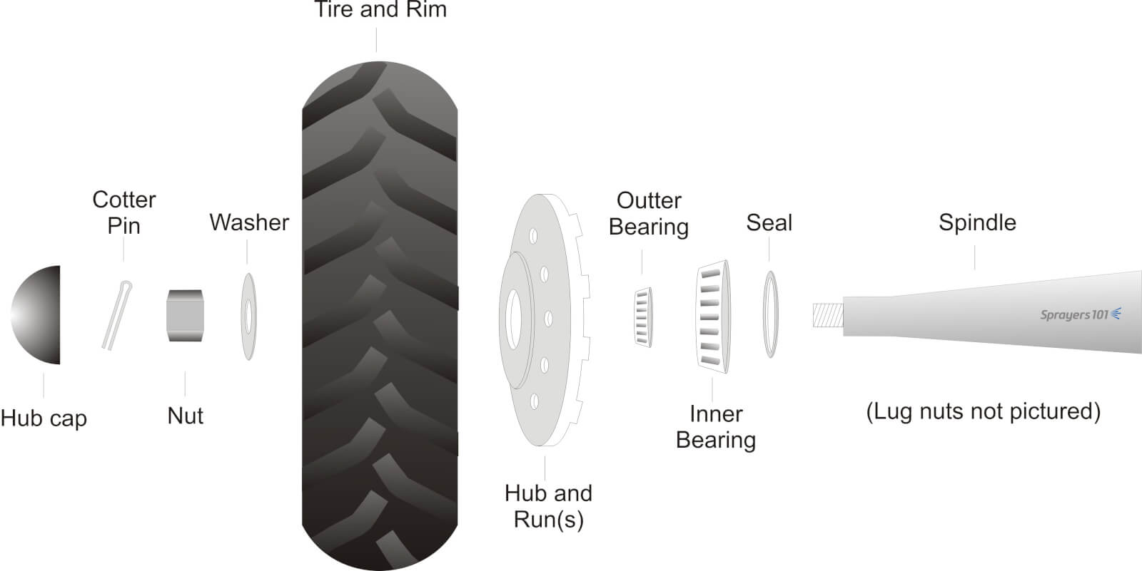
    Sprayer wheel assemblies should be cleaned and inspected as part of regular annual maintenance. Wheel bearing maintenance before long-term storage may prevent water from corroding the bearings. The exploded diagram details the parts found in a typical trailed air-assist sprayer wheel assembly.

    Exploded diagram of typical airblast sprayer wheel assembly.
    Exploded diagram of typical airblast sprayer wheel assembly.

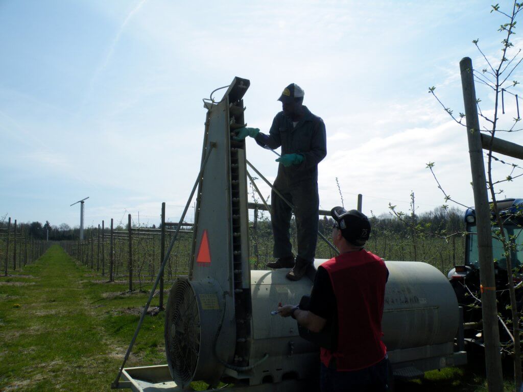
    The following procedure was performed on a 2012 Durand-Wayland sprayer by Mr. Murray Thiessen, Consulting Agricultural Mechanic and renowned “Sprayer Whisperer”. The steps are applicable to most sprayer makes and models. The entire process should take approximately half-an-hour per wheel.

    Step 1

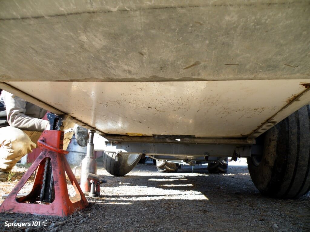
    Empty the sprayer and park it in a well-lit, level spot. Un-hitch the tractor and raise one side of the sprayer using a bottle or floor jack to clear the wheel. Secure the sprayer with a jack stand.
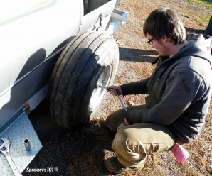
    Raise with one jack, secure with another.
    Raise with one jack, secure with another.

    Step 2

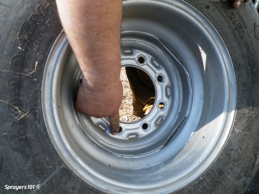
    Remove the lug nuts and take the wheel off the hub. Do not remove the wheel and hub together because it is heavy and you might bang the delicate seal on the spindle. Check the wheel rim for signs of corrosion or distortion (often caused by either loose or over-tightened lug nuts). Check the tread for wear or cuts and check the tire pressure.

    Remove the lug nuts and take the wheel off the hub.
    Remove the lug nuts and take the wheel off the hub.

    Step 3

    Remove the hub cap and pull out the cotter pin. Then remove the nut and washer that hold the hub on the spindle. Put all the small parts in a plastic container with some de-greaser (e.g. Varsol) to clean the parts and keep them from getting lost.
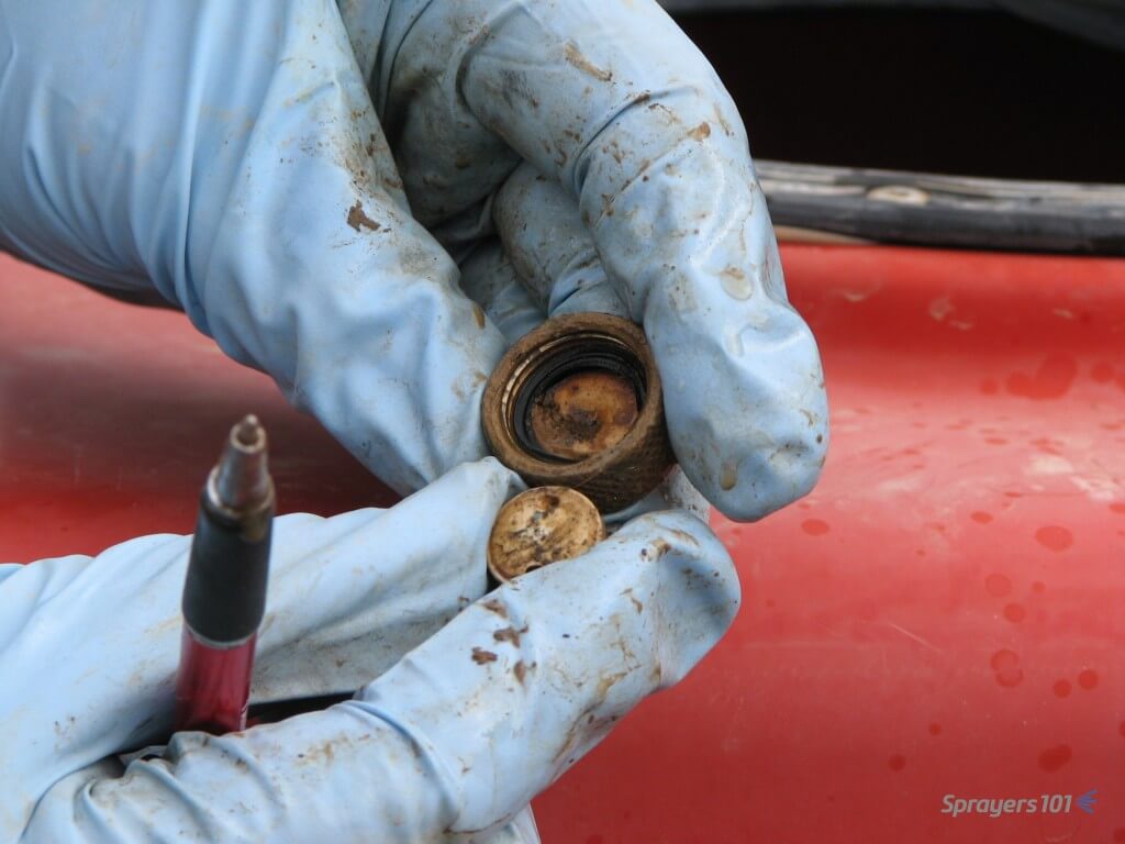
    Remove the nut and washer that hold the hub on the spindle.
    Remove the nut and washer that hold the hub on the spindle.

    Step 4

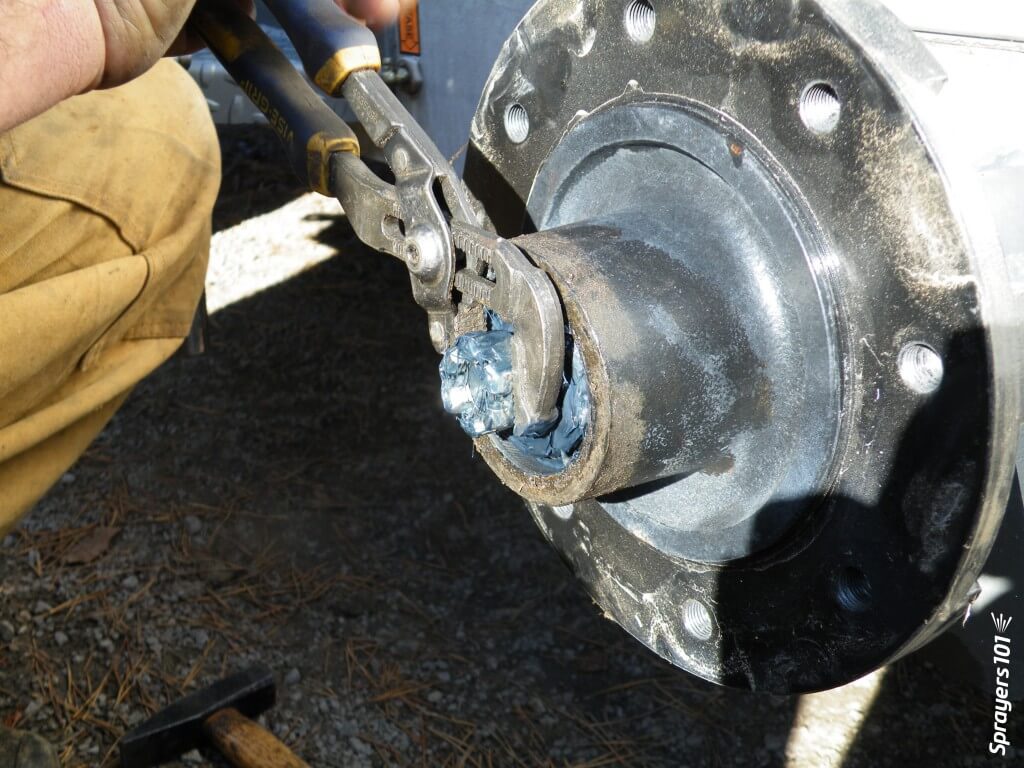
    Knock out the seal and hub bearing and put them in the plastic container. Unless it is damaged, there should be no need to remove the bearing cup (or race) from the hub. The seal is designed to keep dirt out of the assembly, not to keep grease from escaping. Be sure to note which way it is facing. The seal is often ruined during disassembly; have a replacement on hand.
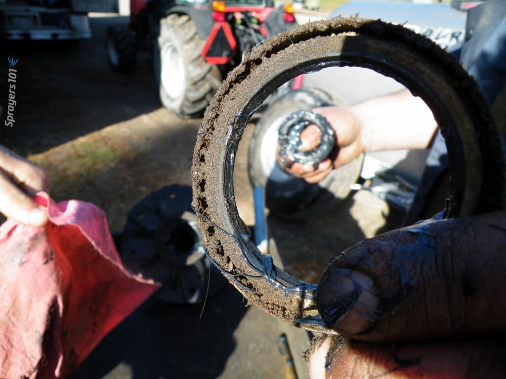
    Knock out the seal and hub bearing.
    Knock out the seal and hub bearing.

    Step 5

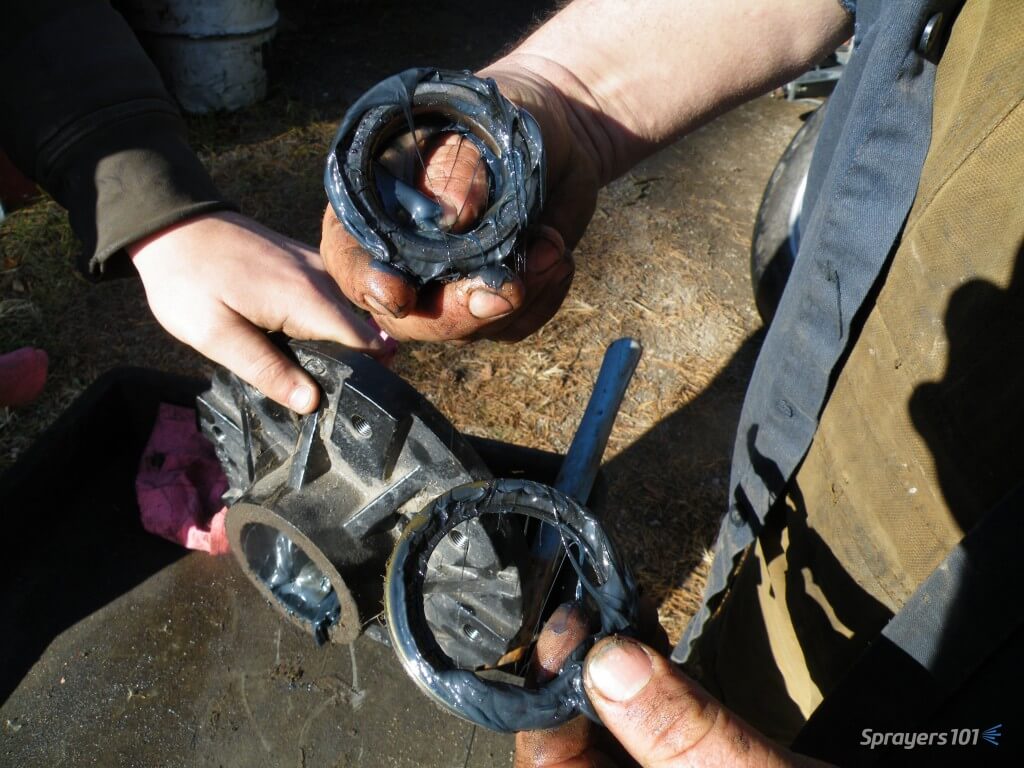
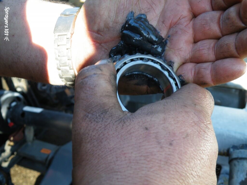
    Clean the old grease out of the hub. This hub has too much and it has filled much of the air space (or cavity) within the hub. That air space is provided so grease is not forced out as the hub heats up, and so dirt is not pulled in as the hub cools. Note the colour of the grease – if it is black and stains your hands, it has burned because too much grease has caused overheating. Look for evidence of dirt or water in the bearing, which indicates seal failure.
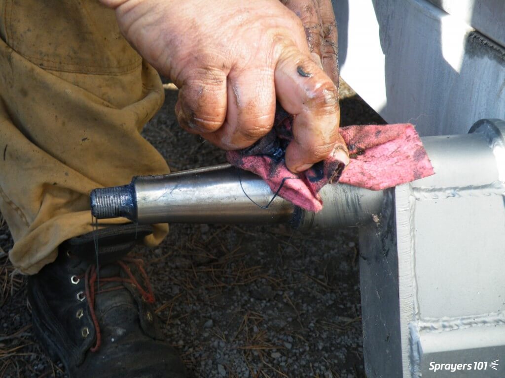
    Clean the old grease out of the hub.
    Clean the old grease out of the hub.

    Step 6

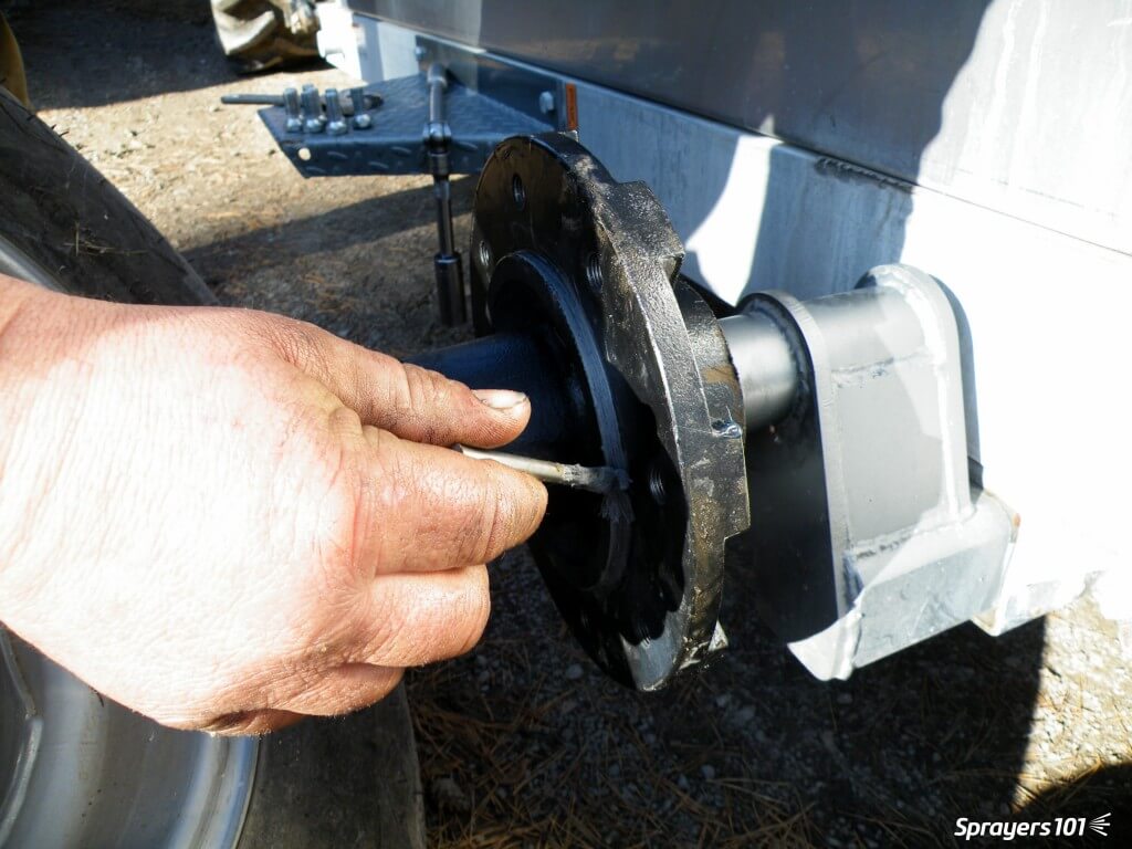
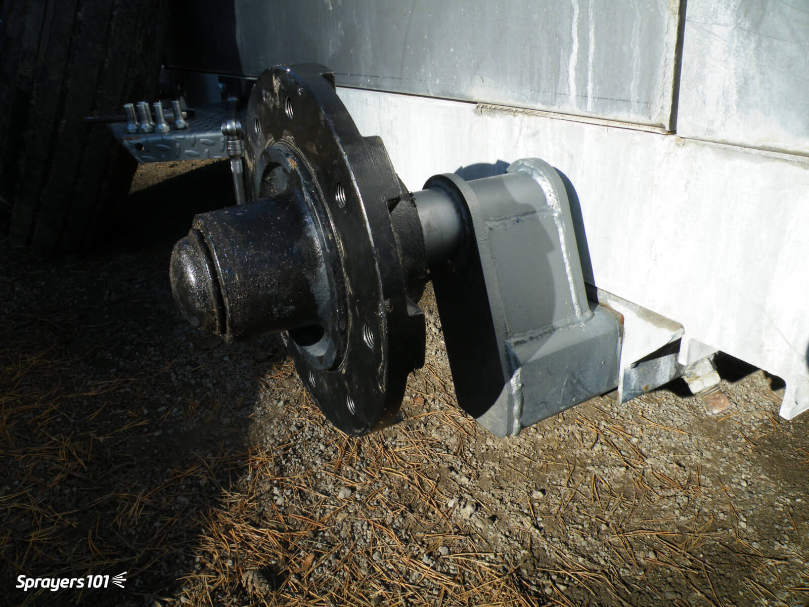
    Wipe dirt from the spindle. Never pressure-wash wheels when they are on the spindles because the spray drives dirt and water past the seal and into the hub. Inspect the sealing surface of the spindle for damage or wear.

    Wipe dirt from the spindle.
    Wipe dirt from the spindle.

    Step 7

    Clean the seal thoroughly. Seals are easily damaged and may need replacement.
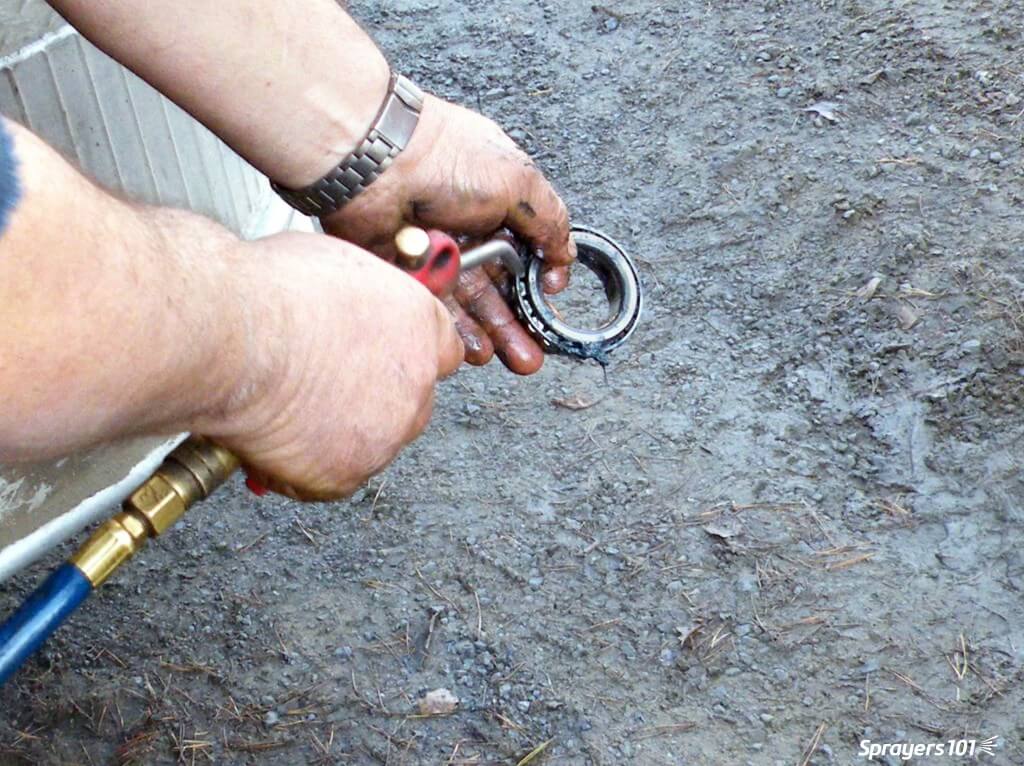
    Clean the seal thoroughly.
    Clean the seal thoroughly.

    Step 8

    Clean the hub bearing. Compressed air is a good way to get all the old grease out, but do not spin the bearing with the air.
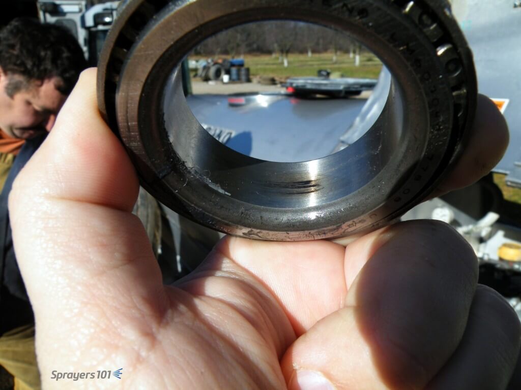
    Clean the hub bearing.
    Clean the hub bearing.

    Step 9

    Look for scratching, pitting or blue metal (indicating heat). This scorch mark indicates the bearing was moving on the spindle, and the friction created heat. Agricultural wheel bearings do not fit tight to the spindles. If there is too much clearance, the bearing race will turn on the spindle where it is not supposed to.
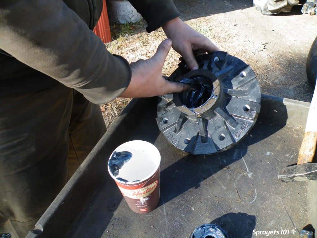
    Look for scratching, pitting or blue metal (indicating heat).
    Look for scratching, pitting or blue metal (indicating heat).

    Step 10

    Repack the bearings, reassemble the hub and re-grease the hub. Bearings should only be ~40% full. Too much grease creates heat and does not let the bearing roll properly. Too little increases friction. No matter which grease you choose to use, never combine greases; they may not be chemically compatible.

    Re-pack and reassemble.
    Re-pack and reassemble.

    Step 11

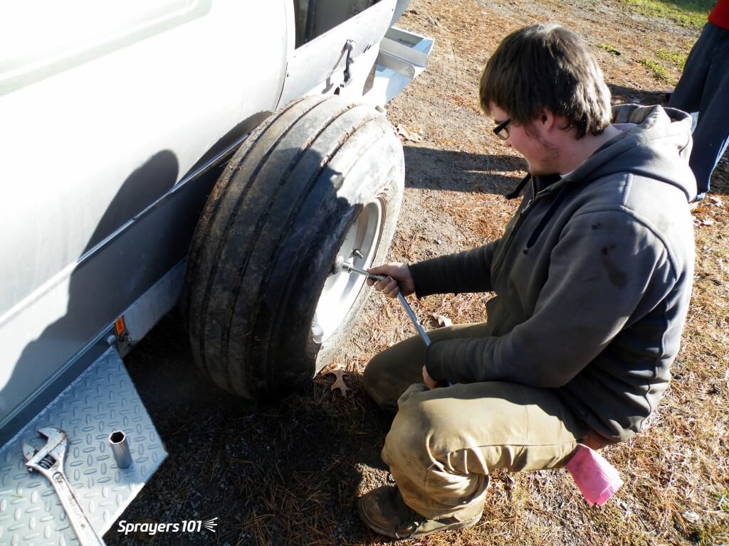
    Mount the hub tightly on the spindle. Replace the washer, cotter pin, nut and cap. There is no need to bend the arms of a cotter pin all the way back – it weakens the metal. Just bend one arm to 90° and cut off the excess. Use anti-seize on the wheel pilot to make the rim easier to remove next time.

    Mount the hub tightly on the spindle.
    Mount the hub tightly on the spindle.
    Some airblast sprayers (such as this Durand-Wayland) have wheel assemblies that can be rotated to four different positions in the chassis. This will raise or lower the sprayer to better align it with the tractor hitch and PTO shaft.
    Some airblast sprayers (such as this Durand-Wayland) have wheel assemblies that can be rotated to four different positions in the chassis. This will raise or lower the sprayer to better align it with the tractor hitch and PTO shaft.

    Step 12

    Replace the wheel and rim. Do not grease the lug nuts or they might loosen. Over- or under-torqueing lug nuts can cause damage. Look in the manual for your correct torque and consider using a torque wrench. Tighten the nuts in a star-shaped pattern – not sequentially.

    Replace the wheel and rim.
    Replace the wheel and rim.
  • Airblast Nozzles – On or Off?

    Airblast Nozzles – On or Off?

    Spray that is not directed at the target is wasted spray. Many pesticide labels specifically require the operator to restrict spray to the target canopy. Spray that escapes above the canopy is a significant source of off-target drift. Foliar applications that extend below the canopy are not efficacious and represent waste and lost productivity.

    A spring application or oil and chloropyfiros. Estimate of 50% waste (in red).

    Air carries spray droplets, so the first step in any adjustment should be to perform a ribbon test to ensure the air outlets are oriented correctly. This is achieved by adjusting deflectors (e.g. low profile axial), the air outlets on a tower, or the entire head on a wrap-around design with individual fan/nozzle combinations.

    Spray height should always exceed the canopy height by a small degree. This compensates for the increase in wind speed with elevation, the potential loss of spray height with faster travel speeds, and uneven alleys that cause the sprayer to rock, which changes the spray angle.

    Spray angles change as a sprayer rocks on uneven alleys. It is more important that spray is directed at the top of a canopy than at the bottom.

    It is less critical that spray align with the lower portion of the canopy. As air energy wanes, or as droplets begin to lose momentum, finer droplets will slowly fall, depositing on random surfaces. Coarser droplets will quickly fall towards the bottom of the canopy, settling primarily on upward-facing surfaces. This secondary deposition can also occur from the cumulative impact of blow-through from upwind rows.

    Once the air is aligned, park the sprayer in an alley. Stand behind the sprayer and extrapolate a direct line from each nozzle to target canopy. Nozzles that point at the canopy should be left on. Nozzles that point above or below can be blocked, or turned off via valves or rotating roll-overs. Some roll-over nozzle bodies can be swiveled up or down 15 degrees to fine tune the spray angle. An alternative would be to permanently rotate the nozzle body fitting in the boom line. When aiming nozzles using a roll-over nozzle body, be careful not to swivel them too far or the valve will partially close and compromise the spray pattern.

    Use a ladder when adjusting nozzles on a tower sprayer. Some sprayer chassis and tanks are designed to accept a climber, but even so they can be slippery. Please be careful.

    When extrapolating, remember that the centre of a nozzle only indicates the centre of the spray pattern. Cone and fan angles can span 60 to 110 degrees, depending on the influence of air. Therefore, even though the centre of the lower-most nozzle intersects the bottom of the target canopy, you may still be able to turn it off because the nozzle above has that portion covered.

    Adjust spray distribution across the boom at the beginning and roughly mid-way through the spray season to ensure the sprayer will uniformly cover the target with the optimal volume. These adjustments should account for both canopy growth and fruit set.

    For example, as the season progresses in an orchard, fruit may cause limbs to hang lower and warrant a new spray distribution. Turning on the bottom nozzle position will help, but it doesn’t account any increase in density throughout the canopy. You may need more volume distributed across the entire boom. Another example: as grape bunches begin to close, sprayer operators may direct fungicides exclusively at the fruit zone and not the entire canopy.

    Remember to always check coverage using water sensitive paper. It’s not worth saving a bit of spray if you’re missing a bit of your target.

  • Reading Airblast Nozzle Tables

    Reading Airblast Nozzle Tables

    Airblast operators should know how to read a nozzle table. They are found on dealer and manufacturer websites as well as in their catalogs. Table layout varies with brand, but they all relate a nozzle’s flow rate to operating pressure. The better tables also provide the spray angle and the median droplet size (i.e. spray quality).

    Operators need this information to complete calibration calculations (aka sprayer math) and when deciding how to distribute nozzle rates, angles and spray quality along a boom relative to the target canopy.

    This article focusses on hollow and full cone nozzles, which are commonly found on airblast sprayers. For more information on flat fan nozzle tables (e.g. for banded under-canopy or, vertical booms or broadcast applications from horizontal booms), refer to this article.

    Reading the table

    Let’s use the table below to determine a nozzle’s flow rate for a given pressure. First, find the nozzle colour in the top row. Second, find the operating pressure in the left-most column. Finally, the flow rate is indicated in the cell at the intersection between the row and column. For example, a red ATR hollow cone nozzle operated at 9 bar will emit a flow rate of 1.83 L/min.

    Perhaps you want to determine which nozzle will give a specific flow rate. Find the rate in the body of the table and trace the column and row to determine which nozzle/pressure combination will achieve it. For example, if we want a flow rate of ~1.00 L/min, we can use a Yellow at 10 bar or an Orange at 5 bar. Yellow is the better choice since the Orange would have to be operated at the bottom of its pressure range (more on that later).

    This Albuz nozzle table for 60 and 80 degree molded hollow cones gives flow rates in litres per minute.

    Note: Do not to confuse TeeJet’s ISO-standardized TXA or TXB nozzles with TXVK or ConeJet nozzles. They may be the same colour, but their outputs are very different.

    Higher flow rates or full cone patterns can be achieved using combination disc and core (or disc and whirl) nozzles. Depending on the manufacturer, the disc plate is defined by it’s diameter in 64th’s of an inch. The core or whirl plate might be described by the number of holes (e.g. 2-hole, 3-hole, etc.), or some other manufacturer-specific nomenclature (e.g. 45’s, 25’s etc.).

    Using the table below, we see that a D2 disc and a DC35 core will emit 0.34 gpm at 80 psi. By continuing along the row, we see that the spray angle for this combination will be 47 degrees at that pressure.

    This nozzle Table for TeeJet disc & cores is fairly typical of any manufacturer’s nozzle table. Find the disc & core combination in the two left-hand columns, and follow the row until it intersects your operating pressure to determine the rate in US gallons per minute. Or, if you know your ideal rate already, you can find the best disc & core combination for a given pressure to achieve that rate.
    This TeeJet nozzle table gives the flow rate for a disc (D#) and core (DC#) full cone combination nozzles in US gallons per minute.

    Pressure problems

    Do not choose a nozzle at the extreme of their flow or pressure range. A trailed PTO sprayer will experience pressure changes from driving on hills, or rate controllers will create pressure changes in response to changes in travel speed. In either situation, coverage will be compromised if the nozzle is pushed outside its optimal range.

    Note: Use pressure to achieve small changes in flow, but for more extreme changes, switch nozzles. Remember, it takes 4x the pressure to get 2x the flow. Stated differently, it takes 1/4 the pressure to get 1/2 the flow.

    You may not find a nozzle/pressure combination that emits the rate you are looking for. When your desired rate or pressure falls between the figures listed in the table, you can take the average. When nozzling an entire boom with different nozzle rates, get each position as close as you can to achieve the overall boom rate for a given pressure. It’s always a compromise – don’t stress over it.

    The author looking up nozzle rates during a spring calibration. The operator was running at 190 psi, but the catalogue only listed 180 psi and 200 psi. When span is only 20 psi, it’s fairly safe to approximate the output. When the table only lists in 50 psi increments, it is more difficult to determine the rate without testing the output. This issue usually occurs at pressures above 200 psi, and that’s very high for most horticultural operations. Consider using a lower operating pressure, if possible.
    Looking up nozzle rates during a spring calibration. The operator was running at 190 psi, but the catalogue only listed 180 psi and 200 psi. When the increment is only 20 psi, it’s reasonable to approximate the output. When the span is 50 psi increments, it is more difficult to determine the rate without testing the output (it’s not a linear relationship). This issue usually occurs at pressures above 200 psi, and that’s far too high for cane, bush, vine and high-density orchards. In these situations, consider using a lower operating pressure.

    Different nozzles, same rate

    Different disc core combinations, or molded nozzles at different pressures, can produce similar flow rates. However, their spray quality and spray cone angles can be very different (see last three columns in the TeeJet table above).

    The angle of the spray cone can have a big impact on spray coverage. When the target is far away from the corresponding nozzle (e.g. the tops of nut trees), or the canopy is very, very dense (e.g. citrus canopies), consider tight-angled full cones under high pressure. This is inefficient and can give variable coverage, but it is sometimes the only option in extreme situations.

    Two hollow cone nozzles on top and five full cone nozzles below. Note the lack of spray overlap with the full cones for the first few meters. This would be a concern if the target were closer to the sprayer, such as grape or berry. Also note that the top two nozzles should not be on; their spray will likely not reach the intended target.
    Oops! Two hollow cone nozzles on top and five full cone nozzles below is the exact opposite of how things should be. Note the lack of spray overlap with the full cones for the first few meters. Spray from the top two positions will likely not reach the intended target.

    When the target is very close to the sprayer, full cones do not overlap and create undesirable striping or banded coverage. Creating a full, overlapping spray swath that spans the entire canopy is a function of nozzle spacing, distance-to-target, and sprayer air-settings. It can also be affected by humidity, wind speed and wind direction at the time of spraying.

    Confirm your settings by parking the sprayer in the alley between crops. With the air on, spray clean water while a partner stands a safe distance behind the sprayer to look for gaps in the swath. The partner will see things the operator’s shoulder check will not reveal.

    Shoulder checks may not show you what’s really happening. Have someone stand behind the sprayer while spraying clean water to see the nozzle spray overlaps sufficiently to span the entire canopy.
    Here’s what the operator sees. But, shoulder checks may not show you what’s really happening. Have someone stand a safe distance behind the sprayer while spraying clean water to see the nozzle spray overlaps sufficiently to span the entire canopy.
    Shoulder checks may not show you what’s really happening. Have someone stand behind the sprayer while spraying clean water to see the nozzle spray overlaps sufficiently to span the entire canopy.
    Here’s what the partner standing behind the sprayer sees. Take a picture with a smartphone to show the operator.

    Nozzle tables can be wrong

    Sometimes nozzles do not perform per the nozzle table. We have discovered errors in published tables, worldwide. Here are the big three:

    • Conversion errors. Manufacturers publish catalogs in Metric and in US Imperial, but we have found many errors in the conversions.
    • Spray angle errors. When nozzles are operated at the extremes of their pressure ranges, spray angles deviate from those listed in the tables.
    • Flow rate errors. When tables are not updated to reflect changes in nozzle design, or the manufacturing process, actual flow rates deviate from those listed in the tables.

    Perhaps it’s not the table, but the nozzle itself. Most nozzle manufacturers accept a flow variability up to +/- 2.5% for new nozzles, but we have seen higher. It depends how they are made (machined, stamped, printed) and the material they are made of.

    Validate flow rate and pattern

    When errors are discovered and reported, the manufacturers can be slow to issue corrections and the errors will persist in old tables. Yes, even apps (which are often based on tables) can be wrong. So, predicted flow rates can prove unreliable. This is why it is important to double check by observing nozzle overlap and validating flow rate when you replace nozzles – even when they are brand new.

    Thanks to Dr. David Manktelow (Applied Research and Technologies, Ltd., NZ) for input into this article.

  • Airblast Maintenance Inspection – the Morning Walkaround

    Airblast Maintenance Inspection – the Morning Walkaround

    An airblast sprayer inspection is part of preventative maintenance. This daily activity identifies small problems before they become big ones. You can do it at the filling station, so it’s fairly convenient.

    Don’t think of it as stealing time from your spray day… it’s part of your spray day. Don’t skip it. If time is tight there are many other ways to improve your work rate.

    This spray plane was left on the runway with the engine exposed for less than four hours. When the owners returned they found a precocious bird had built a nest. Perform regular sprayer inspections – you never know what you’ll find! Photo Credit – S. Richard, New Brunswick.
    This spray plane was left on the runway with the engine exposed for less than four hours. When the owners returned they found a precocious bird had built a nest! Perform regular sprayer inspections – you never know what you’ll find. Photo Credit – S. Richard, New Brunswick.

    Note: Always wear appropriate personal protective equipment (as indicated on the product label), including hearing protection.

    Inspection steps

    Follow this generic inspection process. If your sprayer manufacturer or manager advises additional steps, be sure to perform them.

    Before filling

    1. Work with a rinsed sprayer parked on level ground (e.g. the filling station).

    2. Check lines/hoses and fittings for signs of wear or cracking. Leaks or bulging may only become apparent under pressure (see Test spray).

    3. Filters, screens, strainers and nozzles are clean and unbroken. Leaks may only become apparent under pressure (see Test spray).

    As a plastic suction filter ages, it can warp or become brittle. When this happens, the O-ring may no longer sit correctly and the unit may allow air to be drawn into the lines. They should be cleaned and inspected after every spray-day.
    As a plastic suction filter ages, it can warp or become brittle. When this happens, the O-ring may no longer sit correctly and the unit may allow air to be drawn into the lines. They should be cleaned and inspected when the sprayer is rinsed.

    4. Engage each nozzle shut-off valve or nozzle body flip position. They can seize or loosen with time.

    Begin filling

    5. Begin filling the sprayer 1/2 full with water.

    6. For PTO-driven sprayers, confirm universal joint(s), sprayer-tractor hitch and all connections are clean, lubricated and secure.

    7. Check that all guards (e.g. PTO shaft shield) are in place and intact.

    8. Ensure fan blades are unbroken and scraped clean. Intake grill(s) must also be clean and unbroken.

    9. When 1/2 full, stop filling and check tire pressure (tractor and sprayer).

    Test spray

    For multi-row sprayers, you may have to move the sprayer off the fill pad for the test spray; it’s easier with the air off, if possible. Perform the following steps:

    10. Open the manifold valve to fill the lines and begin spraying clean water.

    11. Ensure each nozzle sprays correctly. Get out of the cab to inspect, don’t just shoulder-check. This gives the opportunity to double-check for line-bulges and leaks.

    12. Ensure the agitation / bypass system is functioning properly.

    13. Check that the tank is secure on the chassis and both crack and leak-free.

    Complete filling

    Continue filling. Once the sprayer is back up to 1/2 full, mix products per usual. If your sprayer manufacturer advises contrary or additional steps for a sprayer inspection, be sure to perform them.

    Checklist

    Sprayer inspections become repetitive, so it’s easy to accidentally miss things. Have you ever driven home while preoccupied, only to discover you don’t remember how you got there? Download our checklist to keep you engaged and to help ensure accuracy. Consider printing and laminating it for repeated use with a dry-erase marker.

    You never know what you’ll find during an inspection. I found a robin’s nest hidden on this vineyard sprayer’s pump.”
    You never know what you’ll find during an inspection. I found a robin’s nest hidden on this vineyard sprayer’s pump.

    Anyone that operates heavy machinery should perform a preventative maintenance inspection before using the equipment. It’s no different for airblast sprayer operators; embrace the daily walkaround.

  • Airblast Calibration – Clearing up Confusion

    Airblast Calibration – Clearing up Confusion

    “Sprayer calibration is an important part of any crop protection program.” Everyone says so, so it must be important. But what exactly are they asking you to do, and why?

    When delivering presentations I often take the opportunity to ask audiences to define airblast sprayer calibration. Their responses cover a wide range of activities that can be rolled up into three related, but quite different, definitions:

    1. Sprayer maintenance inspection
    2. Adjusting sprayer configuration
    3. Validating sprayer output
    Ask a group of managers, sprayer operators, agrichemical reps, gov’t regulators and equipment manufacturers to define “calibration”. Be prepared for very different answers.

    Traditionally, calibration refers to Number 3: Validating sprayer output, but all three are required to ensure a safe, effective and efficient application. Don’t panic – your workload didn’t just triple.

    There is a time and a place for each of these activities. Some should be performed more often than others, but none of them are difficult. This is easier to accept when you realize that only a portion of the spray-day is actually spent spraying. Filling, travel time, cleaning and calibration-related activities are all essential components.

    Let’s consider each activity.

    Sprayer maintenance inspection

    This is more maintenance than calibration (e.g. is it properly connected, is it worn out, is it plugged, is it leaking?). It should not be confused with spring start-up or winterization. For those lucky readers in temperate regions, “winterization” is preparing the sprayer for long-term storage post season… we just use antifreeze.

    The maintenance inspection is the morning walk-around, no different from what any operator of heavy machinery must do before starting their work day. Learn more about sprayer inspection and download a helpful checklist in this article.

    Here are some nasty disc & cores revealed during a calibration workshop. It certainly explained the poor performance the operator was complaining about. Is it time to replace yours? Photo credit – Dr. H. Zhu, Ohio.
    Here are some nasty disc & cores revealed during a calibration workshop. It certainly explained the poor performance the operator was complaining about. Is it time to replace yours? Photo credit – Dr. H. Zhu, Ohio.

    Adjusting sprayer configuration

    This is an ongoing process whereby an operator makes minor sprayer adjustments (e.g. pressure, travel speed, air settings) to reflect environmental conditions, the product’s mode of action and the nature of the target. Would you apply an insecticide to semi-dwarf pears in high wind using the same sprayer settings to apply a fungicide to nursery whips in high humidity? I hope not.

    The process is more intensive at the beginning of the spray season and again around mid-season (e.g. petal fall or whenever the crop changes sufficiently to require a reassessment). It’s described step-by-step in many articles on this website as well as in Airblast101.

    Yes, it requires an investment of time and effort, but the feedback makes subsequent adjustments faster, easier and more intuitive. There are strategies to reduce the number of adjustments required. Large operations can assign sprayers to blocks with similar crop architecture (e.g. one sprayer works large orchards, another sprayer works young or high-density orchards). Smaller operations can change the order in which crops are sprayed.

    Validating sprayer output

    This accounting activity ensures the sprayer is applying the intended rate at the intended speed. “Sprayer math” is really only theoretical; It helps the operator plan for how much pesticide and water must go in the tank and how long the job will require. How the sprayer actually performs may be a different story.

    According to 1992’s “Tools for Agriculture” a horse can deliver 500 watts of power over 10 hours, but the camel can deliver 650 watts over six. Ontario might not employ camels for spraying, but the old adage still applies: “the right tool for the right job”. Photo Credit – R. Derksen, Ohio. Date and location of photograph is unknown.
    According to 1992’s “Tools for Agriculture” a horse can deliver 500 watts of power over 10 hours, but the camel can deliver 650 watts over six. And you thought establishing tractor speed was difficult. Photo Credit – R. Derksen, Ohio. Date and location of photograph is unknown.

    Validating output, or calibrating, confirms that each nozzle delivers the desired rate and that the sprayer travels at the desired speed, so the crop receives the correct dose with no unexpected left-overs or shortages.

    The operator should perform these activities at the beginning of the season and after any significant change to the sprayer set-up. Examples include new nozzles, new tractor tires, using a different tractor or after replacing a pump or any lines/hoses.

    The validation (i.e. calibration) process is explained in our articles on testing airblast sprayer sprayer output and travel speed.

    Conclusion

    Be sure to perform all three calibration-related activities as required. This will keep records up-to-date, improve your spray coverage, and save you from unexpected sprayer malfunctions – almost all of which are preventable.