“Precision agriculture” is many things to many people. In the context of spraying, let’s define it as “detecting and responding to variability”. One example of precision ag is the use of crop-sensing optics to efficiently and accurately direct spray application. This is nothing new to field sprayer operators, but did you know that before Ken Giles published the first paper on pulse-width modulating nozzles in 1989, airblast sprayers already had crop-sensing technology?
In the 1970s, Bert Roper noted the wastefulness inherent to citrus spraying. Losses to the ground of 30-50% and off-target drift of 10-20% of applied volume were (and still are) not uncommon for airblast sprayers. So, using Polaroid’s autofocus technology, and enlisting the help of a few engineers, they developed an ultrasonic sensor system that enabled a computer to “see” the target tree and engage nozzles accordingly. He and son Charlie built prototypes in their kitchen before proving it in their family groves, spraying 10 gal/ac instead of the usual 250 gallons. The first Tree-See system was sold to Cola-Cola in 1984.
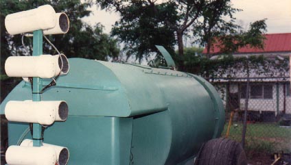
Figure 1 Tree-See on a Swanson sprayer (www.treesee.com)
This technology is still used today; Sensors detect specific zones on the canopy and actuate boom sections, or individual nozzles, to only spray the target zone. But optics and machine learning are evolving. Now they can modulate flow from individual nozzles in response to changes in canopy density. To be clear, that’s not just “on/off”, but variable flow.
Eventually, these systems will be able to identify and respond to specific pests (or pest damage) and adjust plant growth modifier rates based on canopy density or bloom counts. The possibilities are amazing. As an aside, interested readers can learn more about airblast sensors in this excellent article from Oregon State University which one of the authors later summarized for us here.
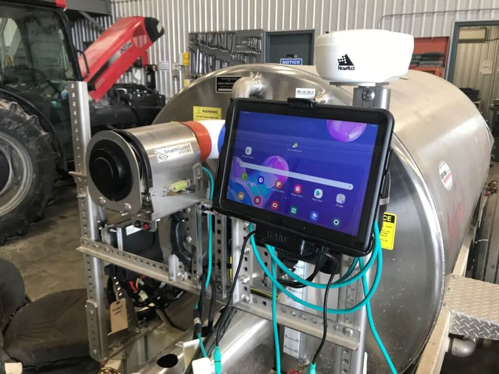
Figure 2 LiDAR and control interface for a Smart Apply system fitted to a Turbomist sprayer
However, as operators embrace this technology, they should be aware of the current limitations. Canopy-sensing optics are great at managing waste (their primary selling point seems to be pesticide savings), but this depends on crop morphology and planting architecture. It makes sense to not spray what isn’t there, but the gaps may not be as big as you think.
Non-continuous canopies require the spray to lead and lag to some extent before and after passing the target to ensure sufficient coverage. Given the difficulty inherent to spraying to the tops of tall canopies, some specialists believe the top nozzles should never disengage. And, in the case of uniform canopies that form continuous hedge-like rows, the potential savings is greatly reduced.
Further, all of these systems assume that application efficiency is primarily dependent on matching liquid flow rates to the profile (or perhaps density) of the target canopy. I don’t believe that’s true. At least, not entirely true. The impact of air settings on coverage efficiency and efficacy seems to have been marginalized.
For example, these sprayers do not account for the spray’s ability to span the distance from nozzle to target (i.e., transfer efficiency). That depends on the droplet size, sprayer air settings and the environmental conditions – none of which are monitored by sprayer optics. They also cannot “know” if the spray gets intercepted by the target (i.e., catch efficiency) or if it deposits a biologically-active residue on the target surface (i.e., retention). Droplets must be retained by the target surface and not bounce or run off.
What this means is that these sprayers, like any sprayer, can only promise “coverage potential”. Operators are still required to perform the following tasks:
Optimize air direction and air energy in relation to canopy size, travel speed and environmental conditions.
Use water-sensitive paper, or some other means of quantifying coverage, to ensure your target receives threshold coverage.
Monitor and adjust practices throughout the season in response to changing conditions.
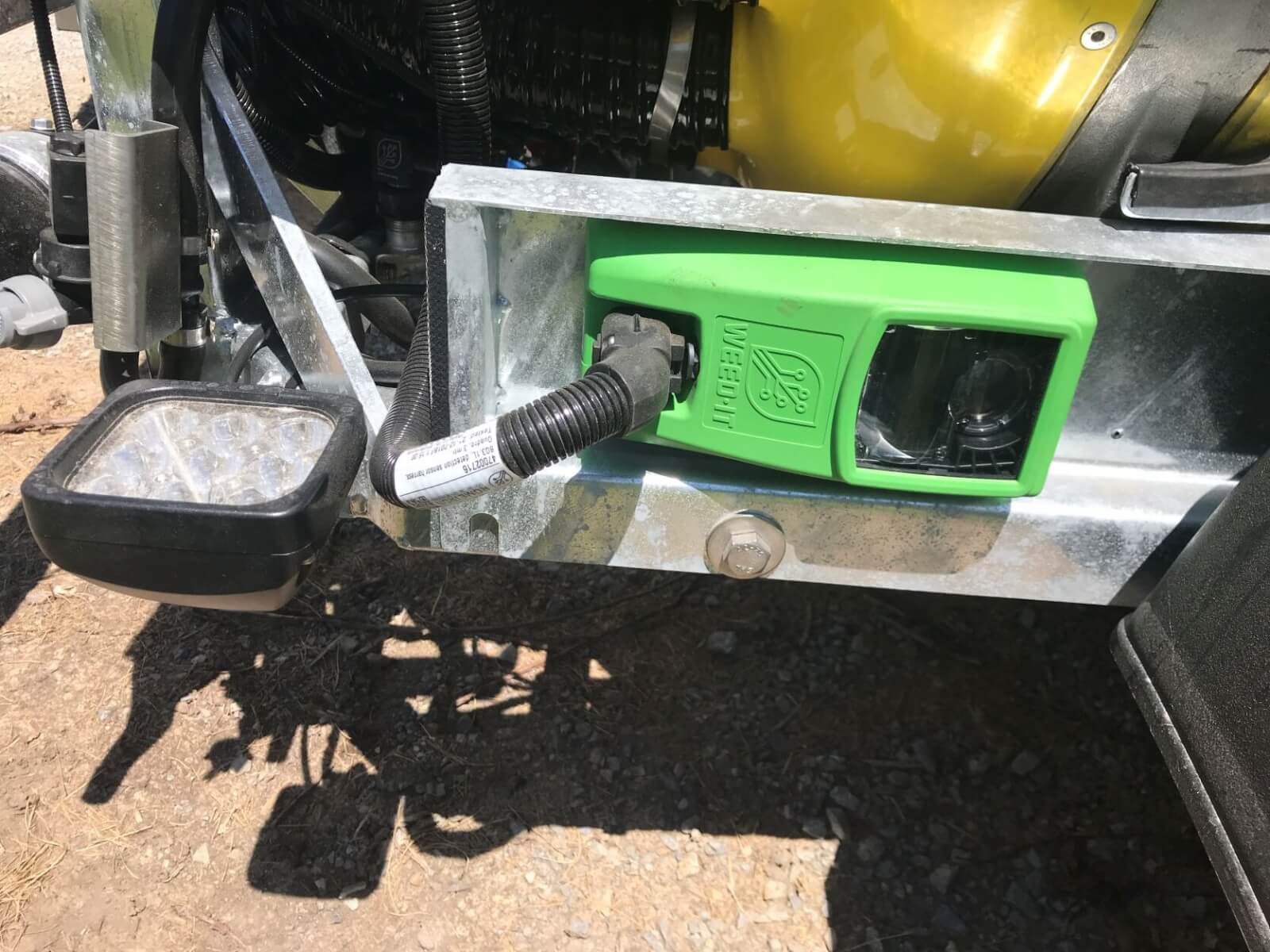
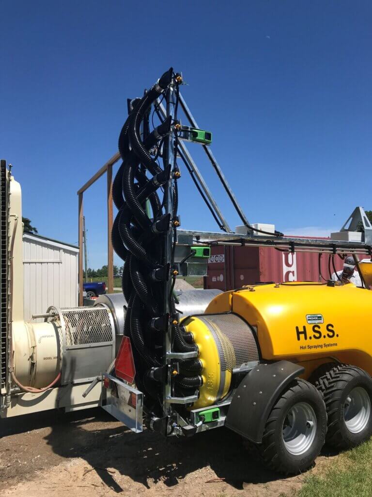
HOL’s Intelligent Spray Application (I.S.A.) system employing Weed-It sensors.
So what’s missing? How do we progress beyond what is arguably a sophisticated rate-controller?
In my opinion, I believe the pitcher needs a catcher – a closed-loop feedback system. Optics would identify the target, nozzle flow would respond, and then a digital spray sensor in the target canopy would detect and report coverage back to the sprayer so machine learning could make iterative adjustments in real-time.
Spray-sensors are not a new idea, as wetness-detection systems have been used in forestry since the 70s. But, a sensor that can discern spray coverage would yield far more detail, and once again it seems Ken Giles is a pioneer in this concept. Such a sensor, integrated with sprayer optics and machine learning, could summarily account for all the unknowns that interfere with spray from the moment it’s released to the point that it (hopefully) lands. That’s some serious crop-adapted spraying.
And yes, it would be fantastic if there were some manner of anemometer tied to a baffle or louvers in the spray head. Air energy could be balanced between up- and down-wind sides, and further adjusted to compensate for the distance to the canopy… but I’m dreaming in technicolour, now.
Until then, sprayer eyes can only blindly dictate the release of spray into the airstream based on an assumed coverage constant (e.g., 1.2 oz./ft3). It remains for the sprayer operator to act as the brain, optimizing sprayer settings, quantifying coverage, and making changes to reflect conditions.
Learn more about how to optimize the fit between your airblast sprayer and your target by downloading a free copy of our Airblast 101 textbook.
In 1977, David Shelton and Kenneth Von Bargen (University of Nebraska) published an article called “10-1977 CC279 Gear Up – Throttle Down”. It described the merits of reducing tractor rpm’s for trailed implements that didn’t need 540 rpm to operate. In 2001 (republished in 2009), Robert Grisso (Extension Engineer with Virginia Cooperative Extension) described the same fuel-saving practice. Again, it was noted that many PTO-driven farm implements don’t need full tractor power, so why waste the fuel? He tested shifting to a higher tractor gear and slowing engine speed to maintain the desired ground speed. 700 diesel tractors were tested, and as long as the equipment could operate at a lower PTO speed and the tractor itself didn’t lug (i.e. overload), as much as 40% of the diesel was saved.
How this applies to Airblast
For airblast operators with PTO-driven sprayers and positive-displacement pumps, this has potential for reducing air energy. Gearing up and throttling down (GUTD) sees the operator reducing the PTO speed from 540 rpm to somewhere between 350-375 rpms, which not only saves fuel but more importantly slows the fan speed. This may be an option when air energy from the sprayer, even at higher travel speeds and a low fan gear, still overblows the target canopy.
Some airblast sprayers, like this one, feature fan blades with manually-adjustable pitch to increase or lower air volume and speed. It’s often a pain to try to adjust them, and most operators only try it once.
A good time to try this out is early in the spraying season when (most) canopies are dormant and at their most sparse. For example, when applying dormant sprays in apple orchards, look to see if the wood on the sprayer-side gets wet, but does not creep around the sides. This suggests that the air, and much of it’s droplet payload, are being deflected. When the air speed is slowed, it will become more diffuse and turbulent on target surfaces, and this turbulence helps more droplets deposit in a panoramic fashion within (not past) the target canopy. Look to see if the wood is wet >50% around the circumference of the branches. You’ll get the rest when you spray form the other side.
Limitations
GUTD is not always appropriate. It requires airblast sprayers with PTO-driven positive displacement pumps (e.g. diaphragm). Airblast sprayers with centrifugal pumps would experience a drop in operating pressure and would have to be re-nozzled. Further, the pump must have sufficient surplus capacity to maintain pressure at low rpms.
GUTD is not intended for air-shear sprayers that employ twin-fluid nozzles because dropping air speed below a certain threshold may compromise spray quality; the air needs to be fast enough to create and direct spray droplets
The tractor must have sufficient horsepower (more than 25% in excess of minimally-required capacity) to permit the reduction in engine torque. This is especially important if the operator is on hilly terrain. If the tractor begins to lug (e.g. black smoke, sluggish response, strange sounds) you’ll be in trouble.
Observations
We first experimented with GUTD in 2013. We noticed how much quieter the sprayer was, and the fuel consumption was certainly reduced. One grower-cooperator switched to a GUTD spray strategy mid-way through their dormant oil application in pears. We saw the trees immediately began to drip. Panoramic coverage was improved significantly; once the operator passed down the other side of the target, capillary action and surface tension helped to give near-complete coverage.
However, in one instance, the operator was already applying a low spray volume per hectare using air induction nozzles and their lowest fan gear. By further slowing fan speed using GUTD, coverage at the top of his cherry trees was compromised.
In short, GUTD can work under the right circumstances. If you want to try it, use water-sensitive paper to establish a base-line with your current practice, and then evaluate coverage after you change your sprayer settings.
Establishing an airblast nozzling solution is an involved process. We must first define the working parameters and flush out any special circumstances. Then we use an iterative approach to identify suitable nozzle combinations that require minimal changes to the sprayer.
This article outlines my process step-by-step and then applies it to a hypothetical orchard scenario. If readers wish to delve deeper into the variables or the reasoning, several links to supporting articles are provided. Be aware that nozzling the sprayer is the penultimate step in establishing optimal sprayer settings. Operators should first adjust air settings, which includes identifying a suitable travel speed. The last step in setting up any sprayer is to verify you are achieving threshold spray coverage.
Step One: Establish sprayer parameters
Is there more than one sprayer available? In diverse plantings, it may be more efficient to assign a sprayer to blocks that require the same nozzling solution.
How many nozzle positions are there on one side of the sprayer? If the nozzle bodies are roll-over style the operator can alternate between two different nozzles in each position. Some designs have twice as many nozzle bodies as needed. The intent is to assign two unique nozzle solutions in an alternating A-B set-up. This additional capacity gives us some flexibility if needed.
Is this a tower or a low-profile axial sprayer? Generally, we distribute nozzle flow evenly over a tower boom but distribute ½ the flow in the top 1/3 of the boom on a low-profile axial sprayer (depending on canopy shape and density). Air-shear and one-sided sprayers are special cases that are not addressed in this article.
What is the average travel speed, and can the operator easily change it? This process assumes the selected speed achieves a reasonable work rate while optimizing the interaction between sprayer air and the canopy.
What is the average operating pressure, and can the operator easily change it? For sprayers with positive displacement pumps, pressure is easily changed via the regulator. Not so for sprayers with centrifugal pumps. Pressure-based rate controllersempower an operator to dial in their desired volume and are easiest of all .
Step Two: Establish target parameters
What is the row spacing (or spacings)? Some operations include a variety of canopy morphologies and planting architectures.
What is the target volume (or volumes)? Operators often use a range of volumes to reflect the product being applied and the canopy area-density. This process assumes the volume will provide threshold, uniform coverage without misses or excess.
Step Three: Are there any environmental, geographical or adjacency concerns?
Each operation is unique, including conditions that may influence nozzling. For example, open water, sensitive crops, or residential areas adjacent and downwind of the planting may warrant drift-reducing nozzles or require the operator to only spray inward from one side of the sprayer. In another example, dry and windy conditions may require nozzles that produce a coarser spray quality will improve their survivability. Rolling hills and uneven alleys may cause sway that prevents the upper-most nozzles from consistently reaching the target.
Step Four: Find out why the operator is re-nozzling
The answer may reveal the operator’s willingness and ability to make changes to sprayer settings. For example, if their objective is to improve the match between sprayer and canopy it implies a willingness to take a more active role in spraying. Conversely, a less experienced operator might be satisfied with a more robust (i.e., wasteful) set up that does not require many changes between blocks.
Step Five: Determine the highest and lowest boom flow requirements
The following formulae relate travel speed, row spacing, and the desired volume sprayed per planted area to the output from a single boom. I recommend downloading this Excel-based calculator to make the process easier.
US Imperial Formula Output from single boom (gpm) = [(Sprayer Output (gpa) × Travel Speed (mph)) ÷ 990] × Row Spacing (ft)
Metric Formula Output from single boom (L/min) = [(Sprayer Output (L/ha) × Travel Speed (km/h)) ÷ 1,220] × Row Spacing (m)
Using the formula with the appropriate units, enter the highest desired volume, the fastest travel speed and the longest row spacing. This will give the highest rate of flow the boom must satisfy.
Repeat this process using the lowest desired volume, the slowest travel speed and the shortest row spacing. This will give the lowest rate of flow the boom must satisfy.
The ultimate objective is to select a combination of nozzles that can produce these two flows, distributed sensibly along the boom, with no gaps or excessive flow relative to the target. Ideally, the operator should be able to alternate between these two flows with as few changes as possible.
Step Six: Satisfy the highest flow
This step requires a nozzle manufacturer’s catalogue and a calculator (or the downloaded Excel spreadsheet). We must assume the range of available nozzle positions are oriented to span the target canopy with no over- or under-spray.
Divide the highest flow requirement by the number of available nozzles. Hypothetically, a nozzle size that produces this flow would satisfy the highest flow requirement while providing an even distribution along the boom.
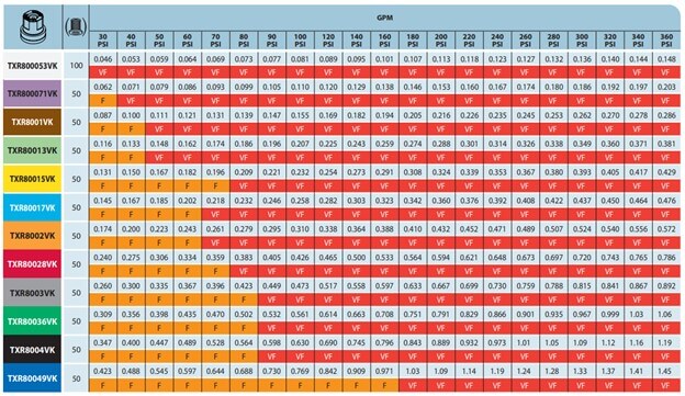
Using the nozzle manufacturer’s catalog, find the flow table for the nozzle you want. Generally, a molded hollow cone nozzle is the preferred choice (e.g., TeeJet’s TXR ConeJet or Albuz’s ATR). If drift is a concern, there are also air induction (AI) hollow cones available. AI nozzles are most effective in the top two or three nozzle positions where drift potential is highest. However, they may require higher flow than calculated to compensate for a reduced droplet count.
Find the operating pressure (it may be in either the column or row heading) and find a flow rate in the body of the table that is as close as possible to your calculated ideal. It’s almost never an exact match, so choose the option that is less than the target rate – not higher.
Imagine placing that nozzle in every available position. Add up all the rates to determine how close you are to the ideal flow. It will likely be less. To compensate, replace the top nozzle on the boom with a higher rate and re-calculate the total flow. Repeat this process, substituting for nozzles with a higher rate, moving top-down along the boom until the flows match.
You have now satisfied the demand for the highest flow.
It is important to note that this process assumes the flow distribution along the boom should be relatively even, perhaps skewed towards the top. However, it is sometimes appropriate to distribute the flow differently to reflect each nozzle’s distance-to-target and the density of the corresponding portion of canopy it needs to spray. This tends to be the case when pairing low-profile radial sprayers with large or trellised canopies, and you can read more about that process in this article.
Step Seven: Satisfy the lowest flow
This is the art-and-compromise part of the nozzling process.
Confirm that the range of available nozzle positions still corresponds to the target. Quite often, the lowest flow is intended for smaller canopies. If so, we may no longer have as many nozzle positions to work with.
Imagine the sprayer is still nozzled for the highest flow per the last step. Leaving the highest effective nozzle on, imagine turning off every second nozzle. Add up the flows and determine how close you are to the lowest rate of flow. It is often still too much. Do not turn off any more nozzles or you may create gaps in the swath.
Instead, return to the nozzle catalogue and re-calculate the flows for the same nozzles, but using a lower operating pressure. Can you make that work? If not, you may have to go back further in the calculation (Step five) and recalculate the lowest flow required using a faster travel speed. This will reduce the demand for flow.
If none of those options are viable you will have to consider re-nozzling. Perhaps that’s swapping a few nozzles to lower rates. Hopefully this only requires the operator to flip a roll-over position, but it may mean using a wrench to remove caps and swap nozzles.
Once you’ve satisfied the lowest flow, the hardest part of the process is complete.
Step Eight: Satisfy the other permutations
The last step is no different than what we’ve already done. Go back to Step Five and calculate the flow for each spraying situation. That is, each unique combination of row spacing, travel speed and target volume. Using the nozzles already on the sprayer, adjust the pattern of nozzles in use (and pressure and/or travel speed if required) until each unique flow requirement is satisfied.
Step Nine: Record the setups, nozzle the sprayer and test the coverage
Be sure to clearly record the sprayer settings required to achieve each flow. Purchase the nozzles and take the time to test each set up using water sensitive paper to ensure coverage is achieved.
A working example
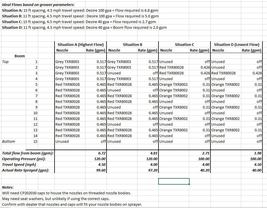
Let’s apply this process in a hypothetical orchard. I’ve included a screenshot of the spreadsheet I use to record the final nozzling solution (below) but feel free to design your own. It includes the nozzling solution for this example.
Our orchard is a 50 acre operation with both 11 and 15 foot row spacings. They have one tower sprayer with 15 nozzle positions on one side and they are not roll-over bodies. The operator wants to apply a 40 gpa volume (concentrated) and a 100 gpa volume (dilute). Their preferred travel speed is 4.5 mph and preferred operating pressure is 140 psi, but they are willing to change them if required.
We use the Excel calculator to work out the ideal highest and lowest demands for flow:
I usually shut off the lowest nozzle position because it almost never aims at the target. Let’s divide the high flow of 6.8 gpm by 14 available positions to give us an average output of 0.48 gpm per nozzle. This operator wants to use TeeJet TXRs, so using their table (below) we see that at 140 psi the Orange ’02 is too low and the Red ‘028 is too large. If we drop the operating pressure to 120 psi, the Red ‘028 is much closer at 0.465 gpm, so let’s do that.
A quick check gives us our current boom flow: 14 positions × 0.465 gpm per nozzle is 6.51 gpm of boom flow. We wanted 6.8 gpm, so let’s go up to the Grey ’03 in the top three positions. Now it’s 4 × 0.517 gpm + 10 × 0.465 gpm = 6.72 gpm. That’s close to our ideal 6.8 gpm, so let’s lock that down. If you want to see what this is in gpa, you can plug the value into the Excel calculator to discover it’s 99.6 gpa. Pretty darn close to our target 100 gpa.
Now using that nozzling arrangement, let’s see if we can satisfy the lowest flow requirement by shutting off every second nozzle position, leaving the highest position on. Doing so reduces us to two Greys and five Reds, totaling 3.36 gpm. That boom flow is much too high compared to the 2.0 gpm we need. However, in our hypothetical orchard, this block has shorter trees so we don’t need the highest nozzle. That drops us to only one Grey and a new total of 2.84 gpm. Good try, but it’s still too much.
Let’s reduce the operating pressure from 120 psi to 100 psi, which is as low as I like to go. According to TeeJet’s table, the Grey produces 0.473 gpm and the Red produces 0.426 gpm at this pressure. This gives us a new total of 2.60 gpm. Still too high! Well, let’s raise our travel speed from 4.5 mph to 5.0 mph and recalculate the lowest flow for Situation D:
This still won’t do it, and driving that fast (even if it’s possible) would change our air settings too drastically. Having exhausted all the easy options we have no choice but to re-nozzle the sprayer for the original lowest flow requirement.
Returning to the TeeJet table we see the best fit is to spray at 100 psi using one Red TXR80028 and five Orange TXR8002s. It’s a lucky break that our 1.98 gpm has come so close to the 2.0 gpm of flow we wanted.
Now let’s work out the best arrangement for the other permutations, Situation B and C. We need 5.0 gpm and 2.7 gpm, respectively. For Situation B, let’s use the nozzling solution from Situation A. We see that shutting off four nozzles gets us very close at 4.81 gpm or 97.3 gpa where we wanted 100 gpa. As for Situation C, let’s work from the nozzling for situation D. By adding a few more nozzles from that set, we can manage 2.71 gpm or 40.2 gpa.
Finally, we record all the settings (refer back to the spreadsheet image). We will need four Grey TXR8003s, ten Red TXR80028s and six Orange TX8002s per side, so 40 nozzles in total (plus a few spares for each rate). We will need to spray at 120 psi for Situation A and be prepared to shut off a few nozzles for Situation B. Situation C will require 100 psi and an entirely different nozzling and we will have to shut a few of them off for Situation D. Not only have we determined a nozzling solution, but we have revealed an efficient order for spraying the blocks that will require as little manual change to the sprayer as possible.
Summary
There is no one right answer to the question “which nozzles do I need” but there are certainly wrong answers. Bear this in mind when you buy a sprayer and the dealer offers you a factory-standard nozzle setup. Apply this process to your operation and be sure to use water sensitive paper to confirm the coverage and to make informed changes where required.
Press Play to hear the audio version of this article
Adjusting Sprayer Settings
Operators are encouraged to adjust airblast sprayer settings to conform to the variability in canopy size, density, spacing, and weather conditions. The efficiency and accuracy of the application is improved through the regular and independent adjustment of travel speed, nozzle output, and air settings.
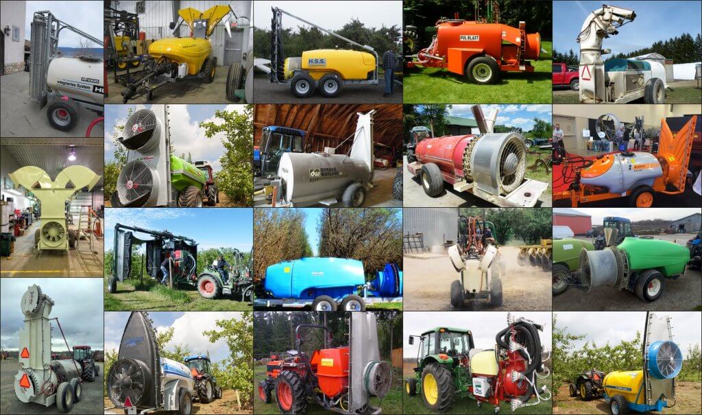
Airblast design is highly variable.
Inflexible sprayer design results in a suboptimal match between equipment and crop. For example, sprayers intended to blow across multiple rows in a single pass are promoted for their high productivity, but typically compromise either coverage uniformity or drift control. In another example, low volume mist blowers utilize high speed air to atomize spray and are promoted as a means for saving water and/or pesticide. But, for many such sprayers, moderating air speed to reduce drift potential causes undesired changes to spray quality.
Even with geared fans, many of Ontario’s airblast sprayers are overpowered for vines, canes, bushberries and high-density orchards. I am uncomfortable with manually obstructing the air intake or adjusting fan blade pitch for safety reasons. Fan gears and travel speed are excellent means for adjusting air energy. Alternately, we have sometimes had success reducing air energy by gearing the tractor up and throttling down (GUTD), but it’s only for very specific situations.
It has been my experience that centrifugal pumps on axial airblast sprayers can undermine adjustment efforts when spraying small to medium sized canopies (i.e. not tree nut or citrus). In the case of GUTD, slowing the fan reduces pressure at the nozzle. Modest pressure regulation may be possible, but typically the operator must swap to larger nozzles to maintain flow. Hollow cone nozzles are only available in large flow increments (average 0.5 gpm), and stepping-up often results in excessive flow. The operator may be able to increase travel speed to compensate, but this frustrates the original intention by affecting dwell time: air settings must now be reconsidered.
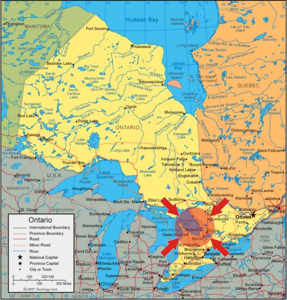
Within this context, why do some Ontario airblast operators still choose airblast sprayers with centrifugal pumps? Let’s consider Ontario’s Georgian Bay area, which many manufacturers, distributors and mechanics refer to as “the last bastion of the centrifugal pump in Canada”.
Remember as you read on, Ontario’s airblast crops are predominantly small to moderate sized canopies. Centrifugal pumps are a common and appropriate pump for large canopies like tree nut and citrus.
Airblast Pumps (in Ontario)
The Georgian Bay region of Ontario.
Airblast sprayer design is highly variable, featuring a diversity of pump styles. Piston (or plunger), peristaltic, tractor-hydraulic driven centrifugal pumps are but a few. Historically, piston pumps and centrifugal pumps on John Bean and FMC sprayers were the airblast norm in Canada.
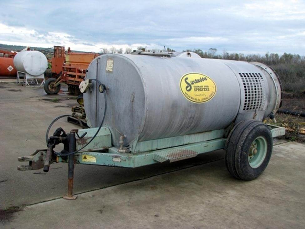
In the 1950s, Georgian Bay was home to Swanson Sprayers (now part of DW), who manufactured airblast sprayers featuring the Myers centrifugal pump. The sprayer was a good fit for the standard apple orchards found in the region. Huge canopies required high volume applications, and the rough and craggy bark harboured mites that drove the need for drenching sprays. To achieve this, sprayers traveled at 5 km/h (3.1 mph) on 7 m (24 foot) spacing, operating at 10 bar (150 psi) to emit as much as 3,750 L/ha (400 US gal./ac). At the time, a diaphragm pump could not manage this, even traveling at 0.8 km/h (0.5 mph).
A Swanson Sprayer (This one likely from Georgia, USA).
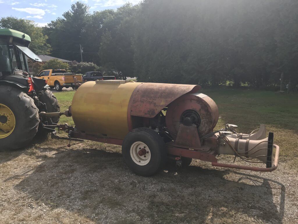
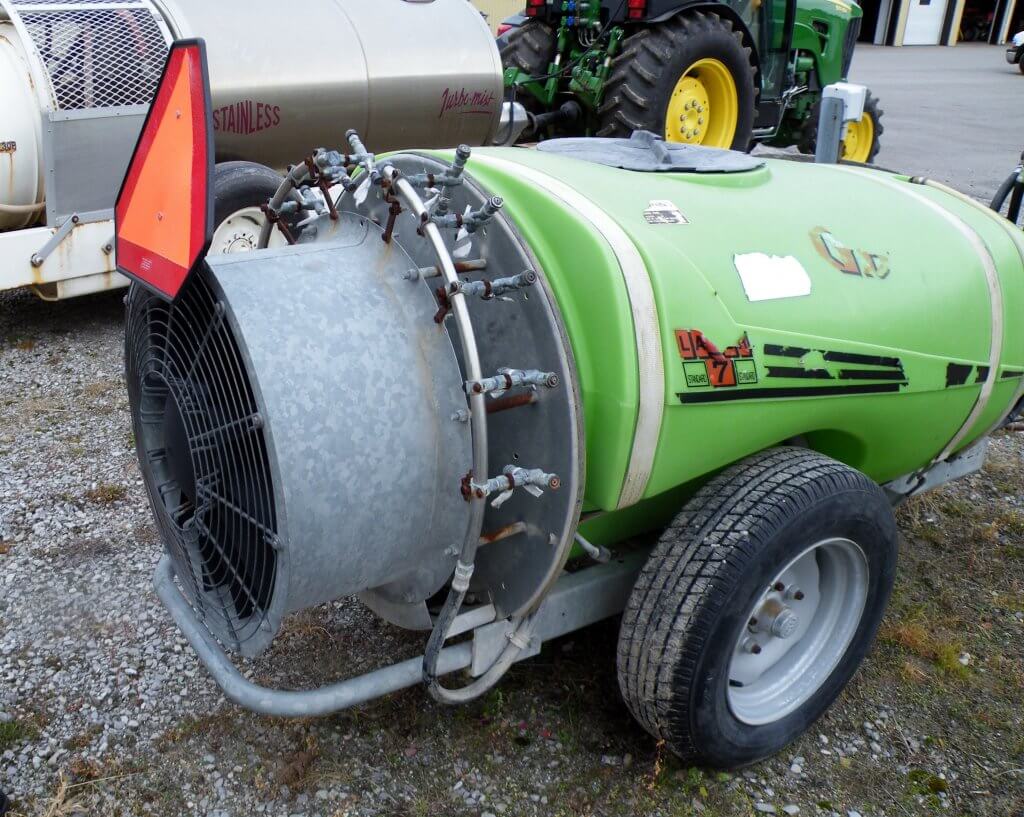
By the 1970s Holland’s Kinkelder air-shear sprayer (centrifugal pump) was introduced to Ontario and promoted as a way to use less pesticide. Perhaps ahead of their time, they never really took off because orchards were still too large for their concentrated (i.e. low-volume) applications. By the 1980s a wave of Italian-made sprayers (e.g. the Good-Boy or GB) featuring diaphragm pumps were imported into the Niagara region by distributors such as Rittenhouse.
Similar to the Kinkelder, this was one of Ontario’s last KWH air shear sprayers. RIP 2018.The Italian-made Good-Boy (or GB).
There were many cases of misuse as unfamiliar operators failed to grease direct-drive diaphragm shafts, ran the throttle beyond 540 rpm or diverted flow intended for agitation to increase flow to the booms. Decreased agitation in relatively large tanks left concentrated spray mix to clog suction filters and destroy the diaphragm pumps. It was an inauspicious start, but the diaphragm pump rallied and today we estimate that 90% of Ontario’s airblast sprayers have diaphragm pumps, while the rest are mostly centrifugal. One Ontario airblast dealer claims to sell 50 diaphragms for every centrifugal, but not in Georgian Bay.
Is it regional history or a long memory of diaphragm “growing pains” that propagate the demand for centrifugal pumps? Perhaps considerations of maintenance, expense or ease of use play a role. Dealers claim that the centrifugal pump is cheaper, but these savings are offset by custom installation costs. Perhaps weather conditions or the crop morphology make centrifugal a better fit? Let’s consider the relative benefits and limitations of diaphragm and centrifugal pumps.
Design
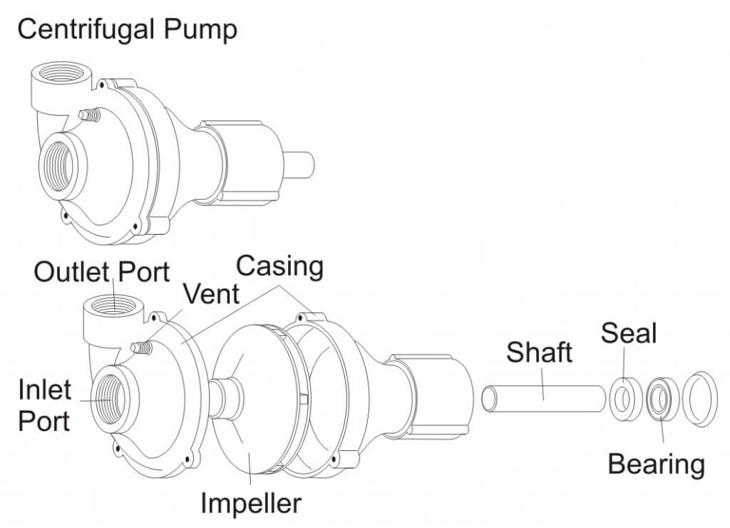
Centrifugal Pumps
Centrifugal Pump – Exploded View.
Most centrifugal pumps prime by gravity feed which is why they are located at the bottom of the sprayer. While less common in Ontario, there are self-priming versions that reserve fluid in the case, or employ clever plumbing, permitting a more accessible location on the sprayer.
Engine-driven centrifugal sprayers are artefacts in Ontario. The more common PTO-driven impeller operates at high speeds, requiring a >1:4 speed step-up mechanism (e.g. gearbox, pulley or hydraulic motor), and unlike diaphragms, they create smooth flow that does not require pulse suppression. While not technically required, most have a relief valve between the pump outlet and nozzle shut off valve to handle changes in pressure.
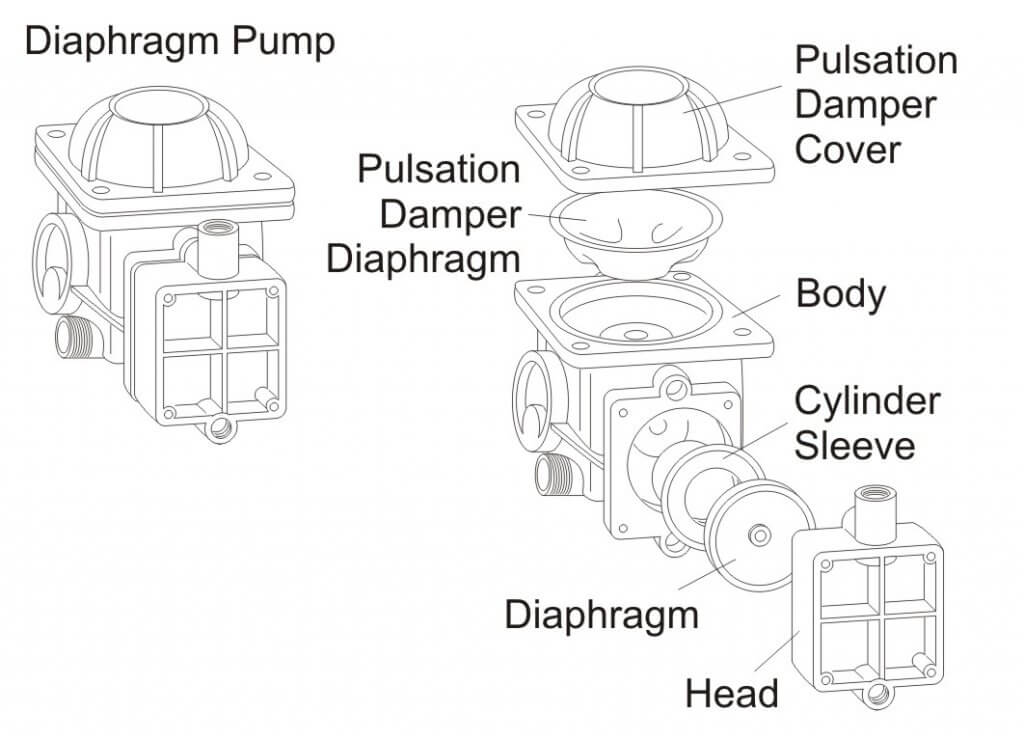
Diaphragm Pumps
Diaphragm Pump – Exploded View.
Diaphragm pumps are self-priming and readily accessible because the shaft runs through the pump to power the fan at 540 RPM, with no need to step-up. Flow is directly proportional to pump speed which in turn depends on the tractor PTO speed. A pressure regulator is used to control bypass flow, which is convenient for making adjustments in nozzle output.
Pump Flow and GUTD
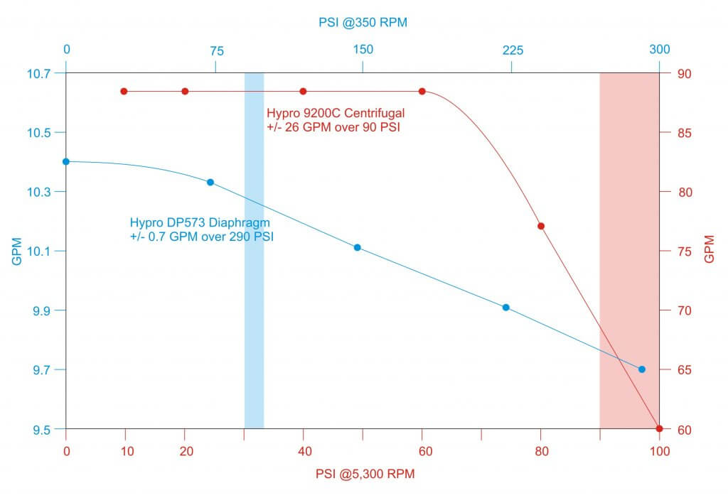
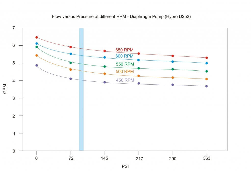
Centrifugal pumps are capable of higher flow at lower nozzle pressure and require more horsepower than diaphragm pumps. Note the large relative difference in flow for a centrifugal pump between the operating pressures of 90 and 100 psi (red curve shaded red) versus that of a diaphragm pump (blue curve shaded blue).
Relative difference in flow versus PSI at constant RPM for a common Centrifugal (red) and Diaphragm (blue) pump. Shaded pressure represents 90 to 100 psi.
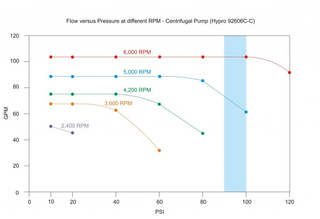
Centrifugal Pumps
The flow curve of a centrifugal pump drops off dramatically; pressure (not RPM) dictates flow. If you were to throttle back on a PTO-driven centrifugal pump, reduced flow would reduce the ability to build nozzle pressure. This means fan speed cannot be separated from nozzle pressure, and reducing air speed means re-nozzling.
Centrifugal flow at different RPM. Shaded pressure represents 90-100 psi.
While (unfortunately) still rare in Ontario, rate control monitors can be used (regardless of pump type) to calibrate output based on a target rate, speed and material flow using travel speed and flow sensors. Nevertheless, they cannot compensate for the aforementioned pressure loss at the nozzle if a centrifugal pump is throttled down to reduce air speed.
In any case, throttling back on a centrifugal pump can cause a condition called suction or recirculation cavitation (aka pinging). Tiny high-pressure air bubbles form on the suction side of the impellor, explosively pitting the impellor. The damage is similar to corrosion and it causes vibration that will wear the pump prematurely.
Any restriction on the inlet side (e.g. clogged suction strainer, collapsed/undersized line) can cause a loss of volume that can damage a centrifugal pump. “Dead-heading” (i.e. closing the outlet) is possible for a short period of time, but it quickly results in heat build-up which can cause damage.
Diaphragm Pumps
The flow curve of a diaphragm pump is flatter and more efficient; RPM (not pressure) dictates flow. If you slow the airblast fan by throttling the PTO below 540 rpm, flow decreases moderately, but surplus capacity allows sufficient flow to the nozzles without pressure drop. As long as the tractor does not lug, there is less noise, lower fuel consumption and therefore operator can typically adjust the air without having to change nozzles. Even if the flow changes the pressure regulator on the diaphragm pump can be used to adjust nozzle operating pressure, precluding a change in nozzle size. Convenient.
Diaphragm flow at different RPM. Shaded pressure represents 90-100 psi.
Diaphragm pumps are capable of high pressure, but are rarely operated above 150 psi in Ontario. Molded hollow cones (eg. TeeJet’s TXR or Albuz’s ATI) operate well in the lower psi range compared to pressure-loving disc-cores. Therefore, while regulators and springs are sized according to the pump’s maximum settings, they do not reflect the usage pattern. The relatively heavy spring is too stiff to compensate for changes in pressure (e.g. driving on hills or closing one boom) behaving more like a fixed bypass and undermining a calibration. The phenomenon is discussed more detail in this article.
Maintenance
Centrifugal Pumps
A centrifugal pump with self-lubricating bearings and quality seals (e.g. carbide) that is maintained seasonally and operated in the best efficiency point of the curve will run reliably for many years.
Proponents of the centrifugal pump claim they are low maintenance (compared to the diaphragm pump). This may be anecdotal, because of the pump’s out-of-sight position on the sprayer and their tolerance for neglect. A mistreated centrifugal pump fails by degrees, often forgotten until a seal leaks or a pressure drop is noticed. In the later situation, increased flow from nozzle wear can mask the problem as the sprayer continues to cover the same number of hectares. Often overlooked, worn or misaligned sheaves/belts on a centrifugal sprayer can also cause a loss of flow. Operators might notice a tail breeze that blows spray onto the belts can cause slippage and lower the nozzle pressure.
Diaphragm Pumps
Opinion is divided on the longevity and maintenance of diaphragm pumps. Some claim they are reliable and low maintenance as long as regular oil changes occur. Others suggest the complication of connecting rods, o-rings and valves require more upkeep than the simpler centrifugal. Unlike the centrifugal pump which merely loses pressure, failure on a positive displacement pump is complete and requires immediate repair
Much depends on the diaphragm material and the products being sprayed. For example, corrosive materials (e.g. copper sulfate, urea, etc.) require polymer manifolds to minimize contact with metal. Metal manifolds do not weather well.
The diaphragm pump can run dry for extended periods. This creates heat but does not often lead to failure. Failures occur from exposure to vacuum, which can happen with dirty suction filters or long and/or improperly sized suction lines, or even lack of oil support on the compression stroke (caused by over-revving).
While three-cylinder designs may not require pulsation dampening, most require an accumulator to suppress the pulsing created by each stroke. Improper adjustment can lead to “hammering” that cracks mounts and valves, and can exacerbate rub-points on hoses. Diaphragm pumps that use direct drive shafts (i.e. carry the PTO to the fan) are subjected to the thrusting of the drive shaft during turns. It is important to keep them greased.
Summarily, the longevity and maintenance requirements for either pump design seem about equal. They depend on the products being sprayed, the quality of pump materials, and adherence to the manufacturer’s instructions on correct usage and preventative maintenance.
Conclusion
Ontario’s airblast-specific crops have become smaller, closer and denser. High liquid volumes and air speeds are typically not required. Operators are encouraged to use Crop-Adapted Spraying to adjust fan speed and nozzle output to the crop and the weather. In my opinion, the diaphragm pump facilitates this, resulting in lowered input costs, reduced drift and improved coverage uniformity. I recognize that this requires skill and effort on the part of the operator, and setting-and-forgetting a centrifugal pump can be attractive, but it’s unacceptable if it leads to unnecessary environmental impact.
In the end, the sprayer manufacturer chooses the pump, atomization and air-handling system while considering safety, effectiveness, reliability and price point. The operator must acknowledge the capabilities and limitations of the sprayer design when choosing the best fit for their operation.
I still don’t know why regions like Georgian Bay seem to prefer one pump over another. Perhaps it’s simply herd mentality. Perhaps they know something I don’t. But consider: an airblast sprayer’s average lifespan is 30 years. That’s a long time to live with a decision.
Choose wisely.
Special thanks to the many dealers, manufacturers, engineers, mechanics and end-users that helped to inform this article.
The role of pressure is often underappreciated in spraying. Many airblast operators (still) don’t use rate controllers, so the only way to monitor sprayer pressure is using a single liquid-filled pressure gauge located near the pump… and it may not be trustworthy. An inaccurate pressure gauge may cause you to spray more or less product than you intended. That translates to wasted resources and potentially higher residue levels. Conversely, spraying less than intended may lead to reduced efficacy and the need to re-apply. Many operators use budget pressure gauges on their sprayers and have never tested or replaced them.
Testing pressure gauges
Here are a few clear indications that your pressure gauge should be retired:
Gauge has an opaque or unreadable face
Mineral oil leaking or mostly gone
Needle does not rest on zero pin when sprayer is not under pressure (it has likely spiked)
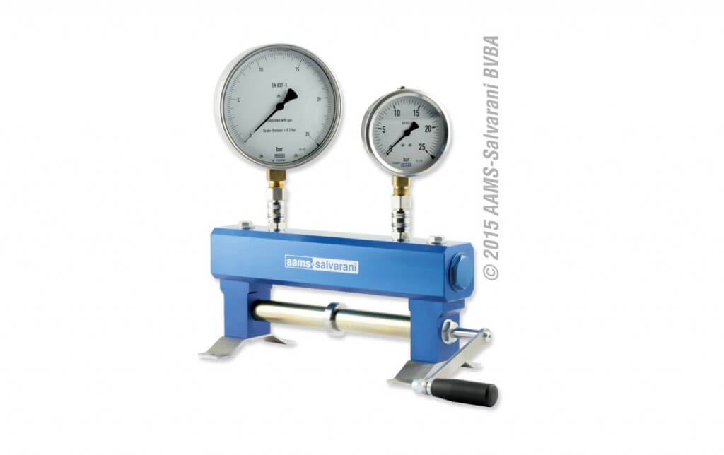
Sometimes a gauge is not obviously in need of replacement. To test it, you need to apply a known pressure to see if it is reading accurately. One way to do this is using a commercial manometer.
AAMS-SALVARANI manometer
These systems work well, but they can be an expensive proposition if you only use them once in a while. In a past sprayer workshop, one participant had a great suggestion for testing gauges. His idea was to use an air compressor (which most farms have) and some simple plumbing to create a homemade manometer. Be sure to vent the gauges before testing.
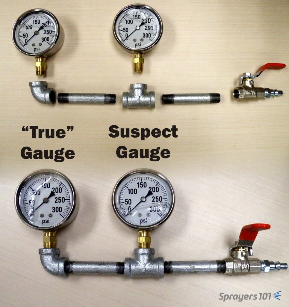
The “Pressure Gauge Tester”. The accurate gauge is in the elbow and is compared to the suspect gauge in the tee. Concept: K. Voege, Ontario.
This tool allows you to test your suspect gauge (set in the tee) against an accurate gauge (set in the elbow) for less than $75.00 CAD. Construct your own “Pressure Gauge Tester” using the following parts (valve optional):
Part
Approx. Price (CAD)
¼” by 3” Galvanized nipples (x 2)
$3.50
¼” Galvanized 90º elbow
$3.50
¼” Galvanized Tee
$3.50
¼” Ball valve (threaded)
$10.00
*Plug Air Connector (A over ¼”)
$4.00
Teflon pipe tape
$3.00
†300 psi liquid-filled gauge
$40.00
*Depending on the quick-connect fitting on your compressor
†The range of the accurate gauge should match your existing gauge. The range of your existing gauge should be twice as much as your typical operating pressure.
As a public service announcement, be aware that many budget, liquid-filled gauges are inaccurate right off the shelf. A 5% variance is typical. When replacing a worn gauge, or buying the “accurate” test gauge for your homemade manometer, buy a few and save the receipt. Test them in different combinations to ensure they all agree with one another. Return the extras and let the dealer know if you discover an inaccurate gauge. I’m sure they won’t put it back on the shelf for the next person… *ahem*.
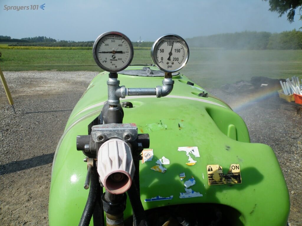
Gauges should be rated twice as high as your average operating pressure. For example, if you typically spray at 150 psi, your should have a gauge rated up to 300 psi. That way, you can see small changes in pressure more clearly. Plus, if your needle is pointing straight up, a quick glance confirms the ideal operating pressure.
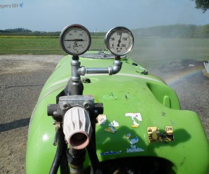
Another way to confirm pressure gauge accuracy is to install a second in-line. They’ll keep one another honest. This may be difficult if the gauge set into a molded plastic tank, or located under the chassis next to the pump where it is not visible from the tractor.
Two gauges keep each other honest – this GB (Italian-made Good Boy) is sporting a home-made assembly that cost ~$75 CAD to assemble. The silver spray paint on the black pipe prevents rust and makes it look pretty darn sharp. Note that they should be the same range, but are not in this photo. The one on the right is the correct range for this operating pressure.
Measuring and Correcting for Pressure Drop
Boom pressure can sometimes be less than the desired operating pressure (a phenomenon known as “pressure drop”) and must be accounted for. Pressure drop is affected by hose diameter, hose fittings, and the distance from the pump. You’ll find it at the far ends of boom sections on field sprayers and it’s an issue that plagues many low-pressure, tower-style sprayers. Dress appropriately because you’re going to get wet performing this diagnostic.
Fill a clean sprayer about half-full with water.
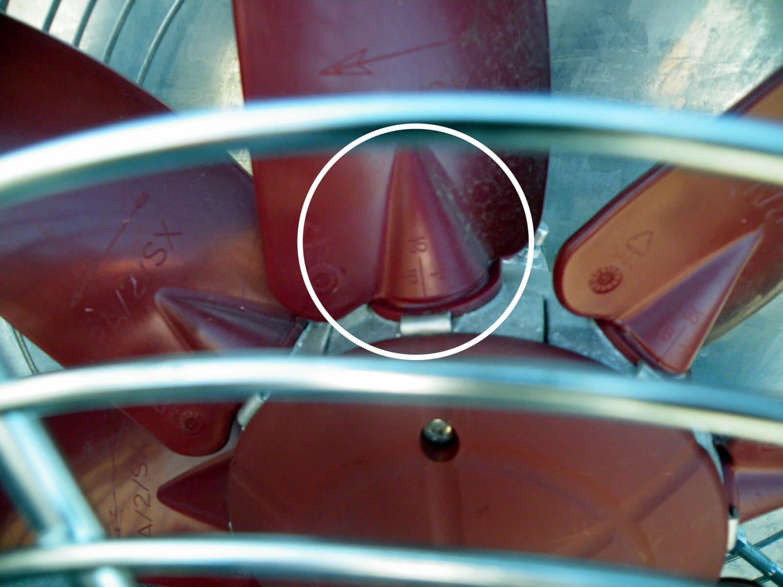
Install a liquid-filled test gauge in the highest nozzle position of one of the booms. The image below shows how the nozzle cap or entire nozzle body may need to be removed for this step. For Metric fittings, contact your sprayer dealer – they can be hard to find.
With the tractor parked, bring up the rpms and get the lines to the desired operating pressure.
Open the boom(s) and measure the pressure at the nozzle farthest from the pump. All nozzles on all booms should be open during this test. That’s why you are wearing PPE.
For positive displacement pumps, adjust the main pressure regulator until the test gauge reads the desired pressure. For centrifugal pumps, it is possible to make small changes to the pressure, but more important to note any pressure differential for later considerations regarding nozzle output and spray quality.
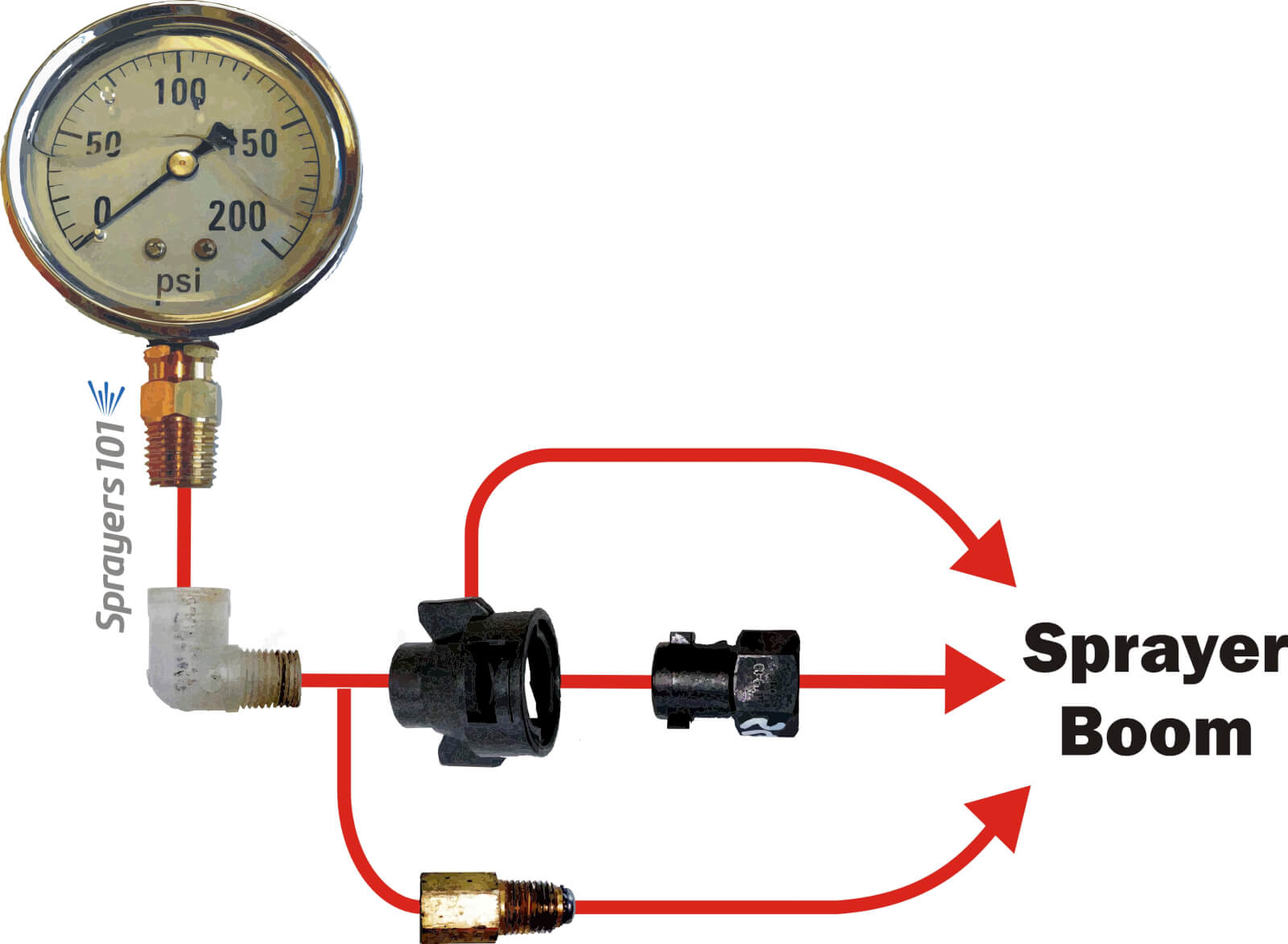
There are many ways to install a gauge onto a nozzle body. Here are three examples of common fittings.
Switching between multi and single boom operation
When sprayers that employ a positive-displacement pump are switched to one-sided operation (E.g., border spraying or during turns), the pressure can change considerably. Most units will experience a pressure increase, thereby increasing the boom output. This is typically an indication of a faulty relief valve, which is positioned between the pump and nozzles. It’s actuated by a spring-loaded piston or diaphragm, opening and closing in response to changes in pressure. The operator sets the desired pressure and any additional pressure forces the valve open, diverting excess flow back to the tank via a bypass.
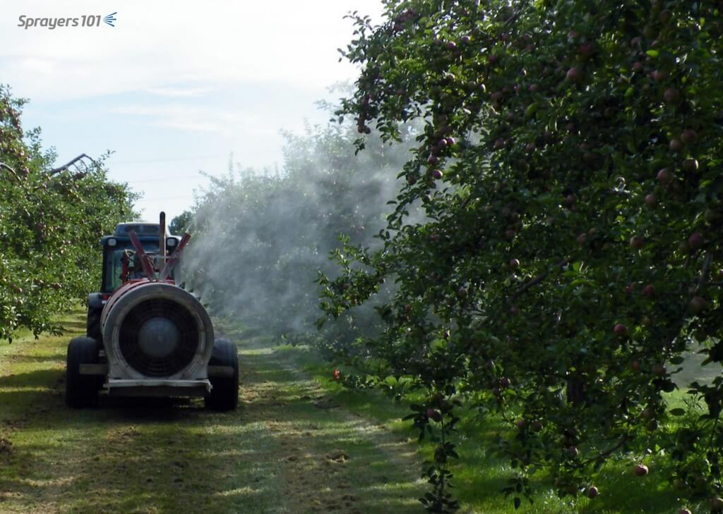
Spraying from one boom. This operator checked to make sure the pressure didn’t increase when he closed the second boom. High pressures or sudden spikes could indicate a faulty relief valve.
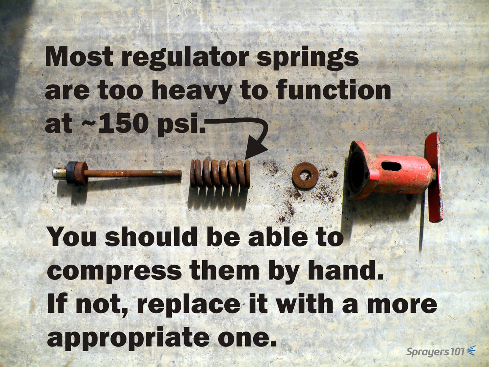
This problem can be greatly reduced by properly sizing the regulator (specifically the spring) to the typical operating pressure. Many sprayers come equipped with regulator springs matched to the maximum pressure range of the pump (often 600 – 900 psi). These springs are unable to respond to changes when operating at lower pressures (E.g., 100-200 psi, which is typical of applications to moderately-sized canopies).
The springs are so stiff that the liquid pressure is unable to act on the spring and the valve essentially acts as a flow control (throttling) valve rather than a pressure control valve. Liquid pressure is difficult to control using a throttling valve; it is unable to compensate if the tractor engine speed drops while driving uphill and sprayer output is subsequently reduced. Further, this phenomenon can cause pressure gauges to spike.
Valve springs and seats wear out, such as in this regulator assembly. Check yours each season. If you spray using moderate pressures, be sure your regulator spring can compensate for small changes.
Some sprayer designs attempt to compensate for excess flow during single-boom operation. They employ an additional throttling valve to shunt the volume that would normally would be spraying out through the closed boom. The result is that the pressure should remain constant when a single boom is shut off. If your sprayer has this feature, here’s how you set the valve:
With PTO at application speed and both booms open, adjust regulator to calibrated operating pressure.
Close one boom.
If pressure increases, open throttling valve to achieve calibrated operating pressure. If pressure decreases, close throttling valve to achieve calibrated operating pressure.
Repeat process for the other boom, and find a compromise position for the valve.
Some operators elect to remove the handle from the throttling valve once it is set so they don’t accidentally bump it later. That’s fine, but further adjustments may be required when transitioning between dilute and concentrated volumes, so don’t lose the handle.
Here’s an oldie-but-a-goodie filmed in New Hampshire in June, 2014. It’s something to keep in mind when you’re getting your sprayer ready for spring service. Thanks to Chazzbo Media and Penn State Extension for making an unscripted and spur-of-the-moment concept into a polished video.