Tag: air

  • Air-Assisted Boom Sprayers

    Air-Assisted Boom Sprayers

    Air-assisted boom sprayers have been around since the 70s. More common in Europe than North America, they have demonstrated value in mitigating drift and improving canopy penetration. The majority of air-assist systems are found on three-point-hitch or trailed sprayers, which is fine (and perhaps even preferable) as long as clearance, travel speed and acreage aren’t limiting factors. In North America, trailed air-assist sprayers are used by some vegetable and strawberry growers, but air-assist in general is rare among field croppers. There are a few possible reasons for this:

    • North American field croppers are predominantly concerned with work rate and prefer the larger, faster, self-propelled option.
    • Air-assist is not ideal for herbicide applications to bare soil because unless it’s perfectly adjusted, it tends to bounce spray off the ground. A canopy is preferred to capture the spray and exhaust the air energy. This reduces the overall utility of air-assist.
    • The air-assist feature is expensive and growers are either unaware or unconvinced of its value.
    • There are few, if any, after-market air-assist upgrade kits available. This is because installations are bespoke; The apparatus is heavy, adds load to existing electrical and hydraulic systems and can interfere with boom folding. So, getting air-assist means purchasing a new (and perhaps unfamiliar) brand of self-propelled sprayer… and there aren’t many on offer.
    Figure 1 – Dammann’s massive three-axel DT3200H S4 self-propelled air-assist sprayer at Canada’s Outdoor Farm Show in 2018.
    Figure 2 – Agrifac’s AirFlowPlus (Image from Agrifac website)
    Figure 3 – Agrifac’s AirFlowPlus depicting adjustable angle (Image from Agrifac website)
    Figure 4 – This photo of a John Deere with air-assist was taken at a dealer’s lot in Southwestern Ontario in 2014. We have no idea what the history is, or who added the air-assist feature (it looks similar to a Miller Spray-Air with two blowers).

    Air assist booms came to Western Canada in the early 1980s in the form of the “Spray-Foil” sprayer, later renamed Spray-Air. This sprayer was developed and manufactured in Carseland, Alberta. It used a shear-atomizer nozzle, a “foil”, that required a strong airblast to properly atomize a liquid feed that was introduced on the foil’s leading edge. As a result, it created a powerful airblast and a very fine spray. It was marketed as a way to reduce herbicide rates, an attractive feature during the times of drought, high interest rates, low commodity prices, and general economic malaise of farming on the prairies during the 1980s. Neighbours of Spray-Foils didn’t like the drift potential of the machines, and chemical companies objected to the claims of reduced water volumes (2 gpa) and lower product rates which contravened label directions. An unflattering test report of the sprayer by PAMI in Lethbridge resulted in a protracted lawsuit which helped cast the fate of the company. A Danish company licensed the design and sold it in Europe under the name Danfoil, where it continues to exist and @Nozzle_Guy saw it in person during the 2019 Agritechnica.

    Figure 5 – A Spray-Air Trident pull-type made in Carseland, Alberta, for sale.

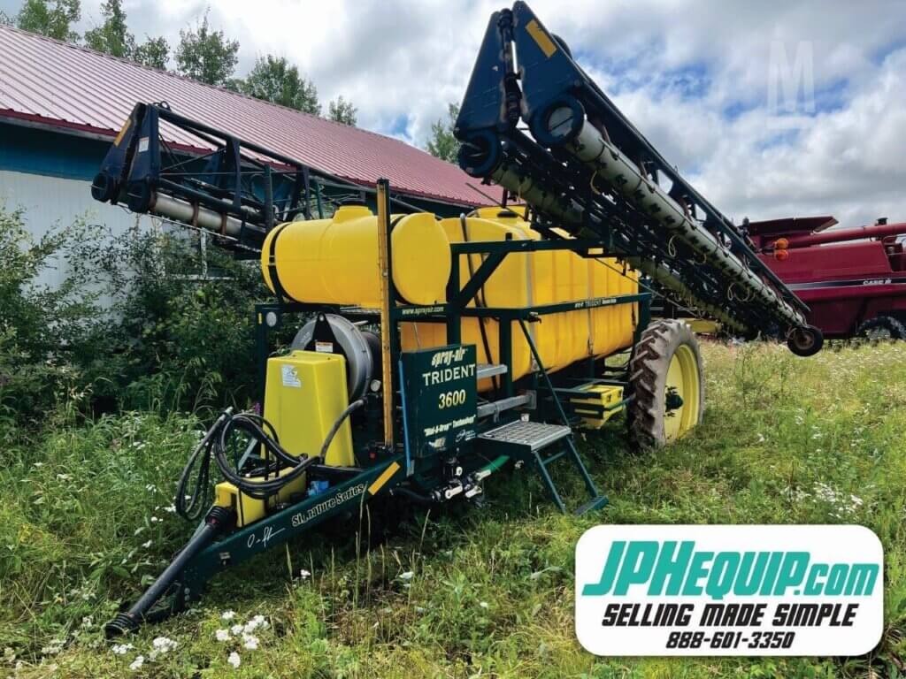
    Eventually, Spray-Air rose from litigation and developed an improved nozzle with the assistance of the National Research Council (the “Shear Guard”) and introduced the Trident boom which gave users the option of atomizing spray with a conventional boom with or without air assistance, in addition the the native choice of shear-atomization. The sprayer chassis itself also continued to improve with a better overall design. Nonetheless, it was sold to Miller in the 2000s after a period of sales stagnation.

    Figure 6 – A trailed one-sided Kyndestoft Air-Sprayer in Ontario field tomatoes (c. 2010)
    Figure 7 – Everyone’s favourite sprayer, the Spra-Coupe, sporting a Kyndestoft Air-Spray system (1996, PAMI)
    Figure 8 – An innovative prototype out of Alberta, the “Kaletsch fan sprayer” used pulleys to power the fans (1996, PAMI)

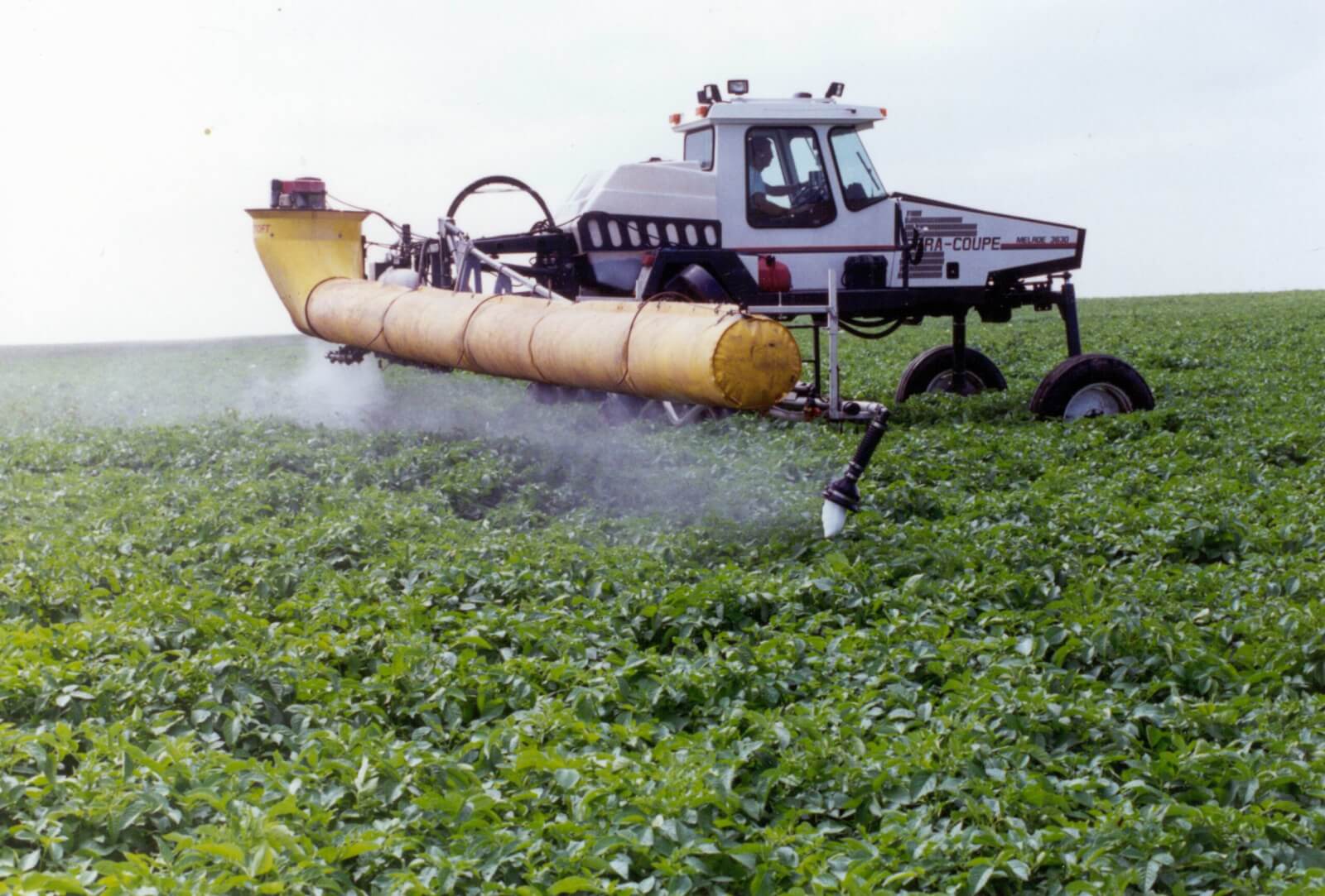
    A fundamental problem with shear-atomization on sprayers like the Spray-Air is the requirement for significant air velocity for the atomization to occur properly. When the canopy cannot absorb that energy, air rebounds and creates drift. And if the operator cannot reduce the airblast strength without adversely affecting atomization, it leads to problems.

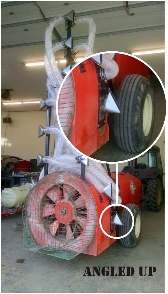
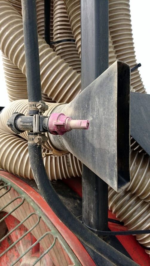
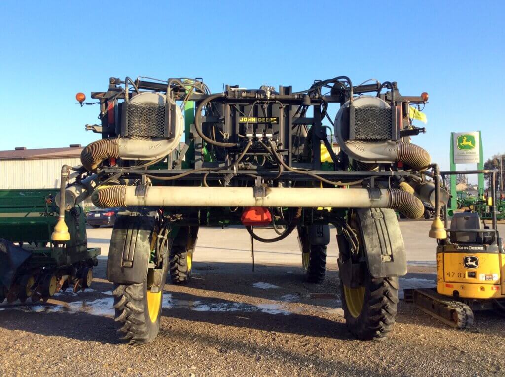
    This photo (Figure 9) was submitted by Mr. L. Jones, a cash-cropper in ND, USA. It’s his JD4710 (circa 2004), which has 100′ booms and an 800 gallon tank. What’s interesting is that it has a Miller’s Spray-Air. This air-assist system is available on Miller’s Nitro and Condor line as well as New Holland sprayers (which are built by Miller). @spray_guy did some work with it on a Condor in field corn. It comes with their dual-flow nozzle system (Shear Guard™ PLUS Air Nozzles plus Dial-A-Drop™) for fungicides (applied at low volume) but you can also use conventional tips for coarser herbicide work.

    Figure 9 – A JD4710 with Miller’s Spray-Air and conventional nozzles.

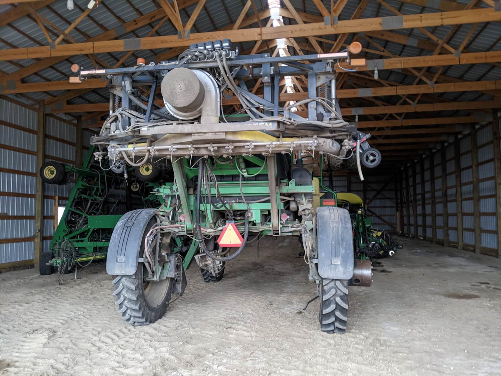
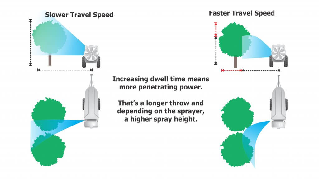
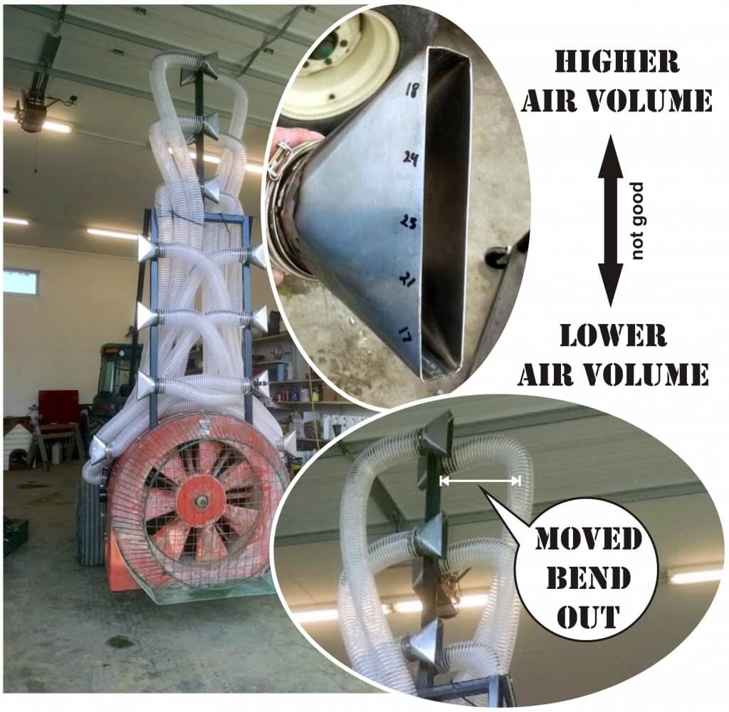
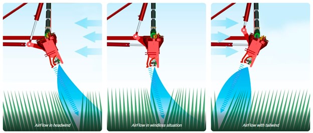
    Mr. Jones says they use the flat fans when spraying a soil-applied herbicide. If it’s moderately windy, they engage the air to reduce drift. When they apply fungicide on wheat they use only enough air to move the heads as they pass over. Bystanders can see the spray enter the canopy and a portion rebounds, which they suggest (and hope) provides some underside coverage. That’s possible, but it’s generally better to keep all the spray in the canopy. This can be achieved by further reducing air speed, increasing travel speed, and/or aiming the air slightly backwards to increase the cross-sectional distance the spray has to travel and slow the spray velocity relative to the sprayer speed.

    Generally, we’re proponents of using air when spraying. It opens the crop canopy, exposes otherwise-hidden surfaces, entrains and carries droplets to the target (reducing drift and improving coverage) and it extends the spray window by out-competing moderate winds. We have no proof, but wonder if it might also help alleviate the negative impact of tire and chassis turbulence on coverage uniformity under the boom. And, before you feel we’ve ignored a big benefit, we’d would be very cautious about using air-assist as a means for reducing carrier volume. The debate about finer sprays at less volume giving greater efficacy continues. While true at times, any benefit needs to be balanced with the downsides of potentially more drift and evaporation.

    Here’s some 2018 footage from an assessment of canopy penetration in field pea using a Miller Nitro with Spray-Air. We see coverage extends deeply into the canopy, the degree of which shares an inverse relationship with depth (fairly classic). Note the heterogeneous mix of smaller and larger deposits from the air-shear nozzles. While some heterogeneity is good, this extreme span represents waste. The product tied up in the largest droplets could have been more gainfully employed as several smaller droplets. This pattern may be the result of using insufficient air energy, preventing the air-shear nozzle from fully atomizing the spray liquid.

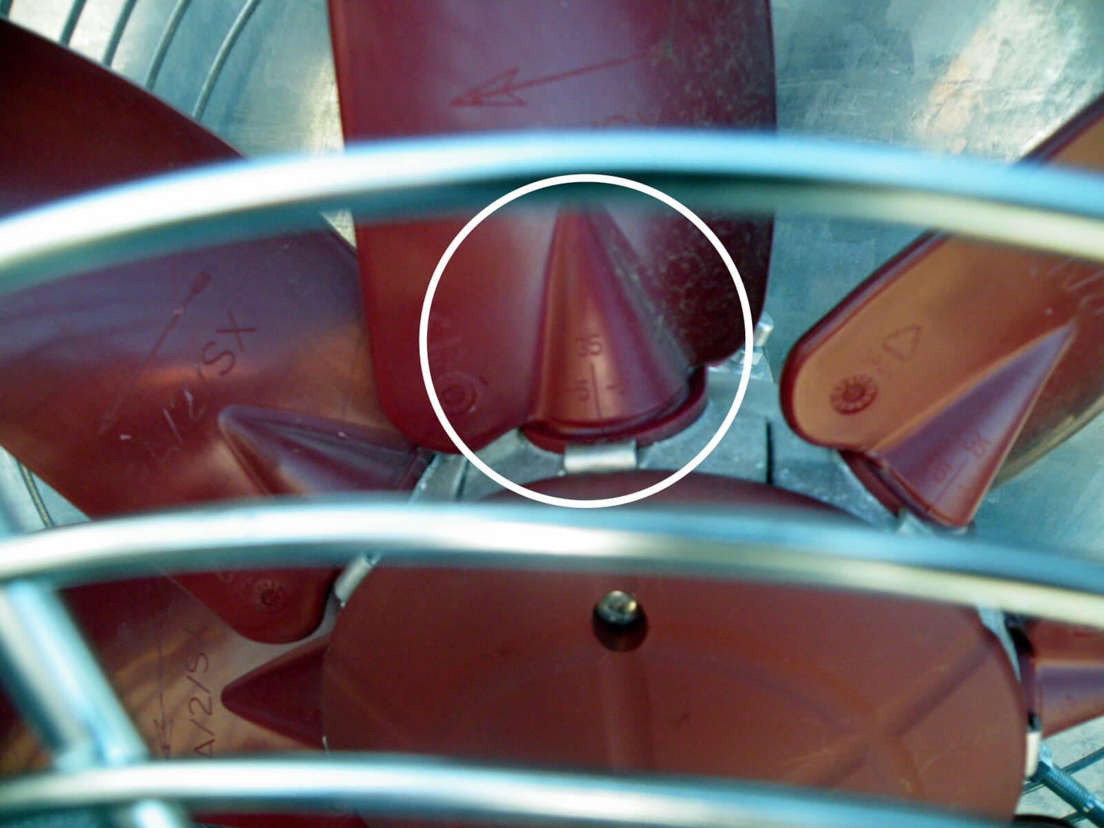
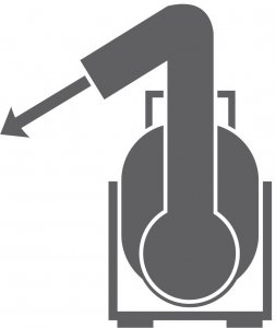
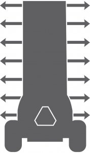
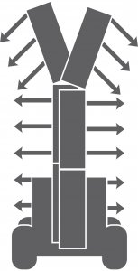
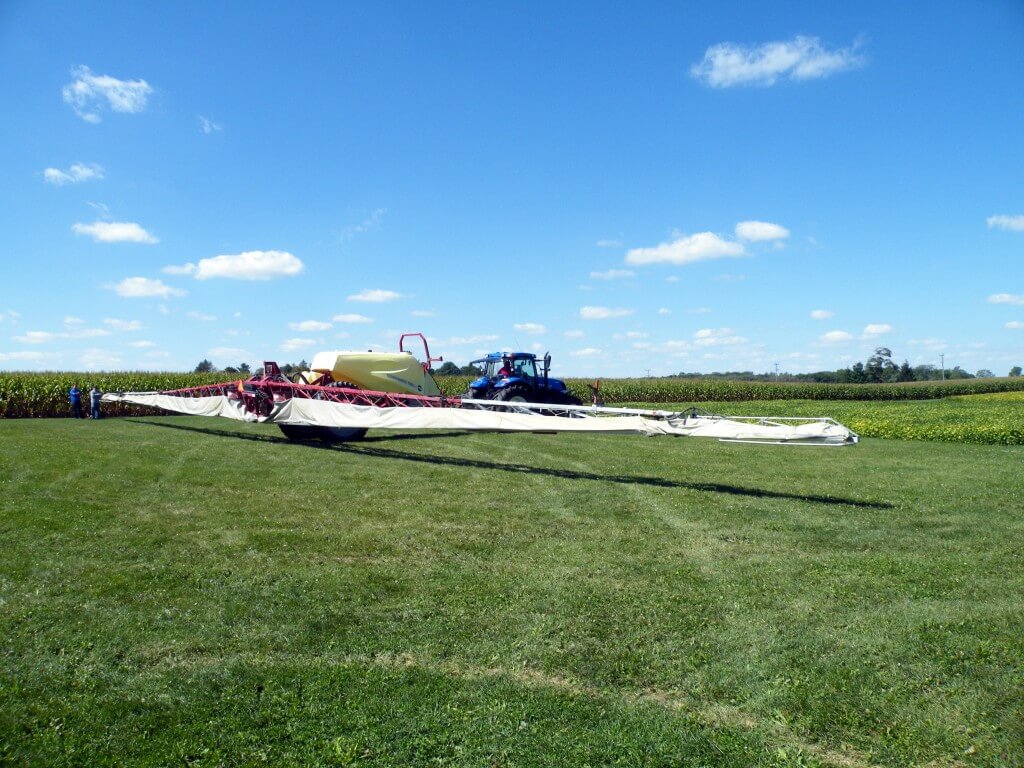
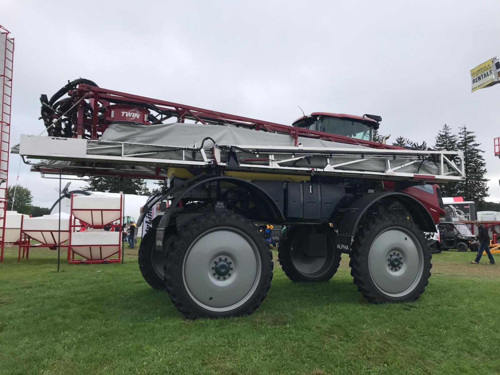
    In 2015 we felt air-assist needed some exposure, so we held a demonstration at Canada’s Outdoor Farm Show. Over three days we used water-sensitive paper to evaluate coverage in a soybean canopy (moderately dense, planted on seven inch centres) from a Hardi Commander (Figure 10) with and without air-assistance. We originally wanted to get our hands on a self-propelled Hardi Alpha Evo (Figure 11), but there were only two in North America at the time and neither were available. By the way, the Alpha Evo is now on the third iteration, but still uses the Twin Force air-assist system which allows the operator to change the angle of the air and the air speed. Each blower can be steplessly adjusted to a maximum output of 2,000 m³/h per m of boom and a maximum (and we’d wager, often excessive) air speed of 35 m/sec. You can watch a video explaining how to dial-in a Twin Force sprayer here.

    Hardi Commander (118 foot boom) with TWIN air-assist
    Figure 10 – The Hardi Commander (118 foot boom) with Twin Force air-assist used in a spray demo at Canada’s Outdoor Farm Show.
    Figure 11 – Hardi’s Alpha Evo self-propelled sprayer employs their their Twin Force air-assist system.
    Figure 12 – Looking up from under the Hardi Alpha Evo boom. Air angle and speed can be adjusted.

    The demo treatments

    The sprayer was calibrated for 93.5 L/ha (10 gpa) at 2.75 bar (40 psi) at 9.7 km/h (6 mph). The boom was suspended 50 cm (20 inches) above the top of the canopy. On one side of the boom, we ran yellow mini drift nozzles (MD 11002’s) to create a Coarse spray quality, and on the other side we ran conventional yellow flat fans (F 11002’s) to produce a Fine spray quality.

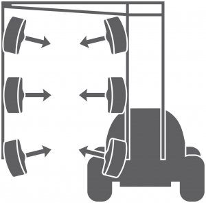
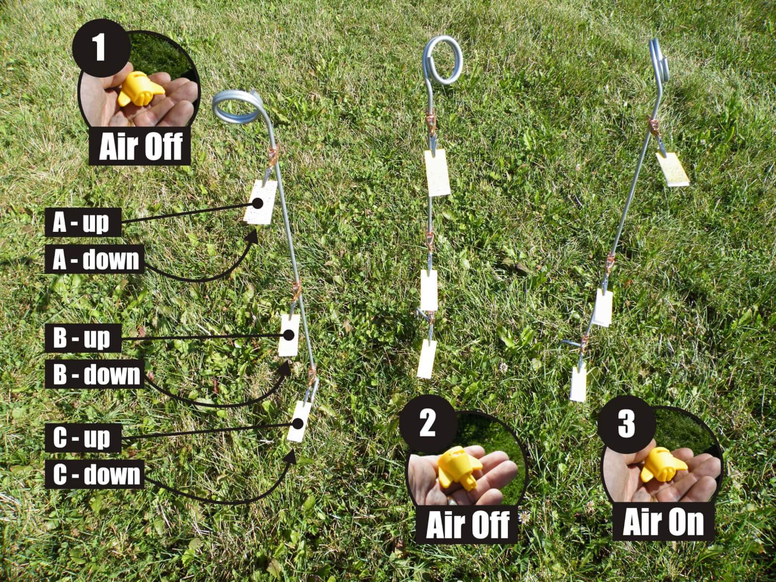
    Water-sensitive paper was attached to rods at three canopy depths: at the top, midway down and at the bottom of the canopy. Papers were oriented both face-up and face-down (Figure 13). Following each application, papers were collected for digital analysis using “DepositScan” which calculates the percent surface coverage and the deposit density. Both of these factors contribute to overall coverage.

    We collected papers from three treatments:

    1. Fine spray quality, No air assist
    2. Coarse spray quality, No air assist
    3. Fine spray quality, Air assist
    Figure 2 - Water-sensitive papers were placed at three levels in a dense soybean canopy, facing up and down, for three conditions. Condition 1 - Air off, conventional 11002’s (medium-fine spray quality). Condition 2 - Air off, mini drift AI11002’s (very coarse spray quality). Condition 3 - Air on, conventional 11002’s (medium-fine spray quality).
    Figure 13 – Water-sensitive papers were placed at three levels in a dense soybean canopy, facing up and down, for three treatments. Treatment 1 (Fine spray quality, No air assist). Treatment 2 (Coarse spray quality, No air assist). Treatment 3 (Fine spray quality, Air assist).

    We held two demos per day at noon and 3:00 pm for three days, giving us six sets of papers to analyze for each treatment. The weather ranged from 25-29°C, 30-58% relative humidity and winds of variable direction from 3-11 km/h.

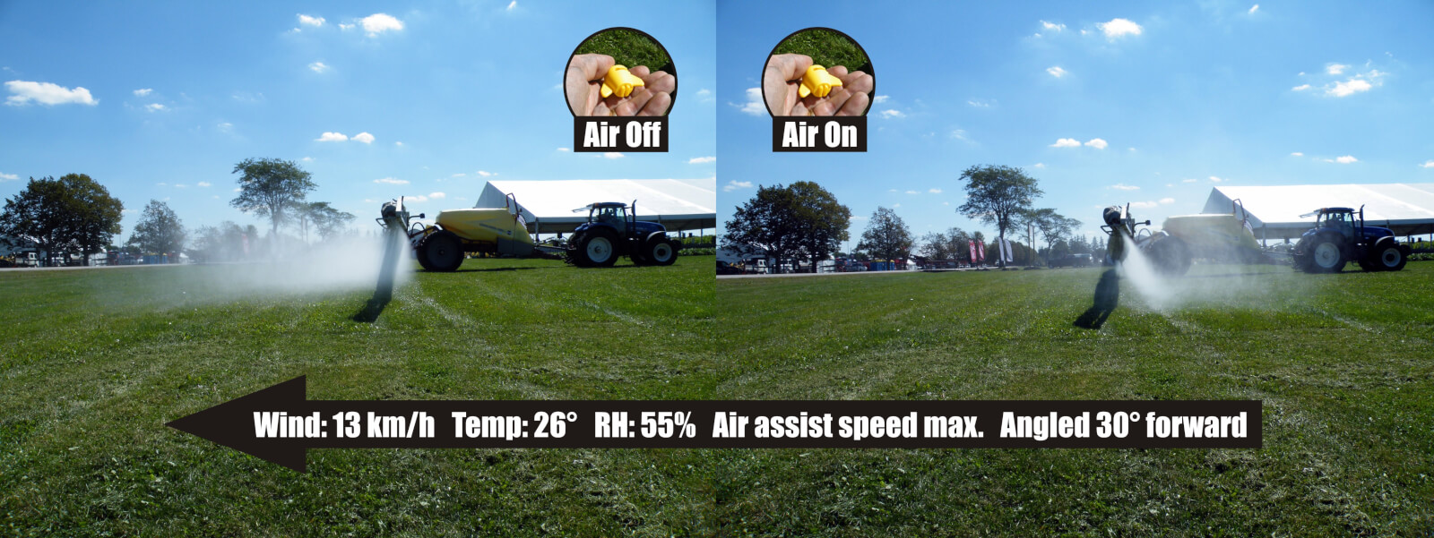
    This was a simple randomized complete block design, but it was not a rigorous experiment. We simply took the opportunity to gather numbers from the demonstration. A more fulsome experiment would require many, many more passes under more stable conditions. For example, we set the angle of the air and nozzles to about 30° forward and the air speed at maximum, which wasn’t necessarily correct. Ideally, these settings should have been fine-tuned to match the forward speed of the sprayer, the density of the crop and the weather conditions. There was a lot of boom sway (watch the video below).

    And so, caveats aside, the following graph illustrates the mean percent coverage and mean deposit density for papers in each treatment, for papers that were facing up (Figure 14). Standard error of the mean is presented alongside the average (x% ± y).

    Results

    Figure 3 – Average percent coverage (red) and droplet density (blue) for upward-facing water-sensitive papers in three canopy depths for each of three conditions. Averages rounded to the nearest 0.5 and Standard Error is indicated. * indicates significance with 95% confidence.
    Figure 14 – Average percent coverage (red) and deposit density (blue) for upward-facing water-sensitive papers in three canopy depths for each of three treatments. Averages rounded to the nearest 0.5 +/- standard error. “*” indicates significance with 95% confidence. Condition 1: Fine, No Air. Condition 2: Coarse, No Air. Condition 3: Fine, Air Assist.

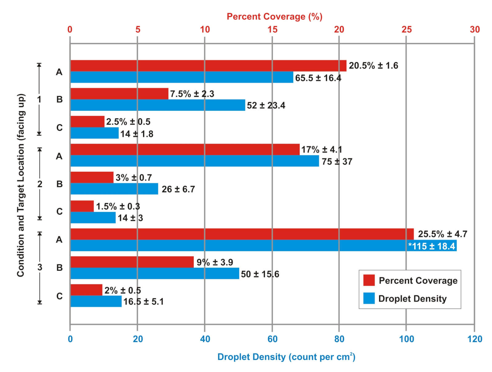
    Treatment 1 (Fine, No Air) reflects a typical coverage pattern for a dense canopy. Coverage declines as a function of canopy depth because spray droplets are intercepted by plant material before they reach the ground. This is particularly evident with broadleaf canopies that create shading. The coverage data doesn’t show it, but there was an obvious (and unacceptable) plume of spray drift during these applications (see Figure 15).

    Figure 4 – The effect of air-assist on downwind drift from a medium-fine spray quality. Note that the nozzles and air are directed 30° forward. When sprayed over bare ground, the air-assist bounces spray back up, as pictured here. However, when sprayed into a canopy with the correct air settings, bounce (and drift) is virtually eliminated.
    Figure 15 – The effect of air-assist on downwind drift from a Medium-Fine spray quality. Note that the nozzles and air are directed 30° forward. When sprayed over relatively bare ground, the air-assist bounces spray back up, as pictured here. However, when sprayed into a canopy with the correct air settings, bounce is virtually eliminated.

    Treatment 2 (Coarse, No Air) follows the same coverage trend as Treatment 1. This treatment represents much larger, and fewer, droplets than Treatment 1, and yet the only obvious difference is reduced coverage in the middle of the canopy. There was little or no plume of spray drift during these applications.

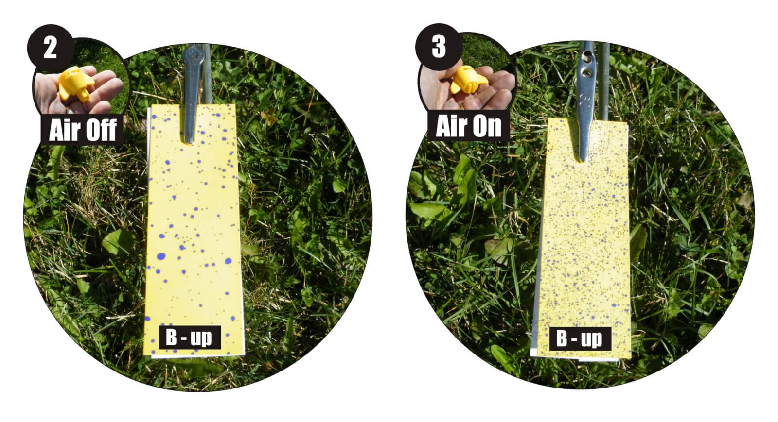
    Treatment 3 (Fine, Air) also followed the trend of reduced coverage as a function of canopy depth. Mean coverage was higher at the top of the canopy compared to the other two treatments. In fact, according to an ANOVA, deposit density was significantly higher in this canopy position than the other treatments, with 95% confidence. While mean coverage in the middle of the canopy was more than 2x that of Treatment 2, it was not statistically significant. There was no apparent difference at the bottom of the canopy. It is important to note that unlike Treatment 1, there was little or no spray drift plume during these applications.

    Figure 5 – Upward-facing water-sensitive paper from mid-way into the canopy (position B) for condition 2 (very coarse droplets, air off) and condition 3 (medium-fine droplets, air on). The difference in coverage is obvious.
    Figure 16 – Upward-facing water-sensitive paper from mid-way into the canopy (position B) for Treatment 2 (Coarse spray quality, no air assist) and Treatment 3 (fine spray quality, Air assist). The difference in coverage is obvious.

    DepositScan was unable to detect coverage on any of the downward-facing papers. However, close visual inspection did reveal differences. Unsurprisingly, Treatment 2 (Coarse, No air)  did not produce any underside coverage; Large droplets do not change direction mid-flight unless acted upon by some other force. Droplets can bounce and shatter, but that did not occur here. The Medium-Fine droplets created in Treatment 1 (Fine, No Air) and Treatment 3 (Fine, Air) did leave trace coverage on the downward-facing surfaces. Generally no more than 10-30 deposits on the entire 1 x 3″ surface, representing less than 1% total surface coverage. It could not be determined if the air used in Treatment 3 improved underside coverage over that of Treatment 1.

    Did air-assist make a difference?

    Let’s start with the literature. Many experiments in peer-reviewed journals show that it does. A perfunctory literature review reveals improved coverage in the middle and lower portions of cotton, potato, soybean and wheat canopies. Some of these experiments were based on coverage using fluorescent dyes, and some with water-sensitive paper. Others were based on efficacy and report improved crop protection. The actual implementation was highly variable with some authors recommending angling the air and nozzles forward 20-25°. Others proposed 30° backwards. Most agreed (as do I) that the air speed should be set relative to the canopy density where higher speeds improved coverage deeper in the canopy, but did so at the expense of coverage in the higher canopy. Picture a bell curve on it’s side where the Y axis is canopy depth and the X axis is coverage; More air shifts the peak of the curve down the Y axis, into the canopy.

    As for our demonstration, some interpretation is required. If an operator is spraying a contact product with limited or no translocative properties, then coverage becomes especially important. In order to improve coverage, higher volumes and finer droplets combined with slower travel speeds are often advised. This may be impractical, as most operators prefer to use less water and drive faster.

    When we used Medium-Fine droplets with no air assist, coverage was good (Figure 14) and better than coverage obtained using Very Coarse droplets. However, spray drift was unacceptable (Figure 15). When air-assist was engaged, we reaped the coverage advantage of smaller droplets and drift reduction as good or better than what we saw with coarser droplets. Unexpectedly, we did not see an obvious improvement in coverage from the air assist. This begs the question “If the spray didn’t drift, where did it go?” This demo was a far cry from a formal mass accounting exercise, but my guess is it wasn’t effectively captured by our collectors and that a hefty fraction ended up on the ground. We would expect more uniform coverage under the boom, and some improvement in canopy penetration, but our ad hoc experiment wasn’t sophisticated enough to reveal it.

    In the end, we feel there are advantages to the air-assist mechanism. The ability to employ a finer spray quality when required, while greatly reducing spray drift and combating inclement weather to extend the spray window are appealing features. Research has clearly demonstrated that deep-canopy spray coverage and overall efficacy are improved when this system is properly adjusted to match spray conditions. We’re not comfortable with suggesting it warrants lower carrier volumes (i.e. not dose) because of the expertise required to adjust the system. However, to be fair, experienced operators have accomplished it

    We hope to see more air-assist options on boom sprayers.

  • Gear up – Throttle down

    Gear up – Throttle down

    In 1977, David Shelton and Kenneth Von Bargen (University of Nebraska) published an article called “10-1977 CC279 Gear Up – Throttle Down”. It described the merits of reducing tractor rpm’s for trailed implements that didn’t need 540 rpm to operate. In 2001 (republished in 2009), Robert Grisso (Extension Engineer with Virginia Cooperative Extension) described the same fuel-saving practice. Again, it was noted that many PTO-driven farm implements don’t need full tractor power, so why waste the fuel? He tested shifting to a higher tractor gear and slowing engine speed to maintain the desired ground speed. 700 diesel tractors were tested, and as long as the equipment could operate at a lower PTO speed and the tractor itself didn’t lug (i.e. overload), as much as 40% of the diesel was saved.

    How this applies to Airblast

    For airblast operators with PTO-driven sprayers and positive-displacement pumps, this has potential for reducing air energy. Gearing up and throttling down (GUTD) sees the operator reducing the PTO speed from 540 rpm to somewhere between 350-375 rpms, which not only saves fuel but more importantly slows the fan speed. This may be an option when air energy from the sprayer, even at higher travel speeds and a low fan gear, still overblows the target canopy.

    Some airblast sprayers, like this one, feature fan blades with adjustable pitch to increase or lower air volume and speed. It’s often a pain to try to adjust them, and most operators only try it once.
    Some airblast sprayers, like this one, feature fan blades with manually-adjustable pitch to increase or lower air volume and speed. It’s often a pain to try to adjust them, and most operators only try it once.

    A good time to try this out is early in the spraying season when (most) canopies are dormant and at their most sparse. For example, when applying dormant sprays in apple orchards, look to see if the wood on the sprayer-side gets wet, but does not creep around the sides. This suggests that the air, and much of it’s droplet payload, are being deflected. When the air speed is slowed, it will become more diffuse and turbulent on target surfaces, and this turbulence helps more droplets deposit in a panoramic fashion within (not past) the target canopy. Look to see if the wood is wet >50% around the circumference of the branches. You’ll get the rest when you spray form the other side.

    Limitations

    GUTD is not always appropriate. It requires airblast sprayers with PTO-driven positive displacement pumps (e.g. diaphragm). Airblast sprayers with centrifugal pumps would experience a drop in operating pressure and would have to be re-nozzled. Further, the pump must have sufficient surplus capacity to maintain pressure at low rpms.

    GUTD is not intended for air-shear sprayers that employ twin-fluid nozzles because dropping air speed below a certain threshold may compromise spray quality; the air needs to be fast enough to create and direct spray droplets

    The tractor must have sufficient horsepower (more than 25% in excess of minimally-required capacity) to permit the reduction in engine torque. This is especially important if the operator is on hilly terrain. If the tractor begins to lug (e.g. black smoke, sluggish response, strange sounds) you’ll be in trouble.

    Observations

    We first experimented with GUTD in 2013. We noticed how much quieter the sprayer was, and the fuel consumption was certainly reduced. One grower-cooperator switched to a GUTD spray strategy mid-way through their dormant oil application in pears. We saw the trees immediately began to drip. Panoramic coverage was improved significantly; once the operator passed down the other side of the target, capillary action and surface tension helped to give near-complete coverage.

    However, in one instance, the operator was already applying a low spray volume per hectare using air induction nozzles and their lowest fan gear. By further slowing fan speed using GUTD, coverage at the top of his cherry trees was compromised.

    In short, GUTD can work under the right circumstances. If you want to try it, use water-sensitive paper to establish a base-line with your current practice, and then evaluate coverage after you change your sprayer settings.

  • Optimizing Sprayer Air Settings – Part 1

    Optimizing Sprayer Air Settings – Part 1

    This is part one of a two part article on how to optimize the match between the sprayer air and the target canopy. For a more fulsome description of the process, consult chapters 3, 9, 10, and 11 of Airblast101.

    Why is air so important?

    Air handling is the most important and least understood mechanical system on a sprayer. Most air-assisted sprayers for three-dimensional perennial crops produce droplets that are Medium or smaller according to the ASABE S572.3 droplet size classification standard. These small droplets have very little mass relative to their surface area, so they don’t have much kinetic energy. Without air to impart speed and direction, most droplets would never go where we want them to. In addition, air opens and moves a canopy, exposing otherwise hidden surfaces to the droplets it’s carrying.

    Imagine throwing a feather. Now imagine throwing it as hard as you can. It may travel a little farther, but not much relative to the extra effort. Even then, an errant gust of wind might change its direction entirely. Similarly, we cannot rely on hydraulic pressure to propel small droplets. This is the primary reason for the “air” in air-assist spraying.

    Air-assist spraying attempts to replace the empty air within a canopy with droplet-laden air (and then get it to stay there). If we don’t have enough air energy, we won’t displace enough empty air and the throw will fall short. Likewise, if we have too much air energy, the throw will extend beyond the the target, wasting spray and likely compromising coverage. Ultimately, we want the air to expend all its energy, spreading, stalling and depositing droplets inside the target canopy.

    Travel speed

    Travel speed can have a significant impact on work rate. However, the effect of travel speed on air behaviour (and ultimately coverage) should be the sprayer operator’s primary concern. There will always be a trade-off between travel speed, coverage and work rate. Travel speed is the first and easiest adjustment to throw, spray height and canopy penetration. Just as travel speed modifies the liquid rate per row, it also modifies air energy per row.

    Environmental and canopy conditions

    Whenever calibrating or adjusting a sprayer, it is critical to do so in the crop, in environmental conditions you would typically spray in. You would not expect a sprayer to achieve the same results in high winds in a dormant vineyard as it would in calm conditions in a mature citrus orchard.

    I recommend using a handheld weather meter because local weather reports often don’t match the conditions in the planting. For temperature and relative humidity, take readings in the shade. For wind conditions, face into the prevailing wind and hold the meter as high as you can. Wind speed increases with height and we want to evaluate the most challenging part of the target – the top third of the canopy.

    Evaluating vertical air angles – Ribbon test part 1

    The air angle (or direction relative to the target) is the first concern. Research has shown that low profile radial airblast sprayers without effective straightening vanes or deflectors make the air go up on one side and down on the other. In extreme situations, this might compromise the spray job (e.g. miss the lower portion of the target on one side of the sprayer) or it might simply waste spray and stir up debris. Here’s how you can see if this is happening on your sprayer:

    1. Park the sprayer in an alley between the rows.
    2. Affix 25 cm (10 in.) lengths of tape along the air outlets. Tie them to nozzle bodies or use duct tape to position them so that they stand out in the sprayer-generated air.
    3. Bring the fan(s) up to the desired speed but do not spray. Stand back behind the sprayer and use the ribbons to extrapolate the air angle relative to the target canopy. Look for asymmetries and wasted air (i.e. angled above the canopy or into the ground.)
    The ribbons on the LPR sprayer in this photo are twice as long as they should be, but fortunately it was a calm day. Note the angles of the lower ribbons compared to the “ideal” broken white lines. The asymmetry corresponds to the misaligned bottom right deflector. Observe the ribbons while adjusting deflector positions. Any ribbons above the upper broken white lines indicate wasted air energy (and likely spray). Large upper deflectors, positioned horizontally, would reclaim wasted air and focus it into the crop.

    By observing the ribbons, you can extrapolate where deflectors or fan heads should be aimed. Air should be adjusted to slightly over- and under-shoot the target canopy. For ducted outlets, such as low profile Turbomist sprayers, the air outlet is not a uniform width – it’s widest about half-way down. Using ribbons to extrapolate air direction, aim the widest part of the outlet at the densest part of the canopy. This automatically repositions the booms as well, facilitating the next calibration step where we turn off nozzles that will significantly over- or under-shoot the target. This is discussed in another article.

    Using a piece of scrap wood with a ribbon on the end to demonstrate how deflectors would channel air on a Florida airblast sprayer. Once convinced, this grower fabricated and installed deflectors and has been very pleased with their performance.
    Using a piece of scrap wood with a ribbon on the end to demonstrate how deflectors would channel air on an Economist airblast sprayer. Once convinced, this grower fabricated and installed deflectors and has been very pleased with their performance.
    When repositioning the air outlets on a Turbomist with no towers, aim the widest part of the outlet towards the densest part of the canopy, then turn off unneeded nozzles. Lubricate the nuts and bolts that hold the outlet bands tight.
    When repositioning the air outlets on a Turbomist with no towers, aim the widest part of the outlet towards the densest part of the canopy, then turn off unneeded nozzles. Lubricate the nuts and bolts that hold the outlet bands tight.

    Video Extras

    These videos are a bit long-in-the-tooth now, but the concepts are still sound. If you hear anything in the videos that contradicts what’s written in the article, go with the article. Live and learn. Thanks to Penn State, the University of New Hampshire and Chazzbo Media for producing these 2014 videos.

    This article will conclude in the second half:
    Optimizing Sprayer Air Settings – Part 2

  • Homemade Air-Assist Tower Retrofit

    Homemade Air-Assist Tower Retrofit

    It was Saturday morning in April, 2016 when I received an email from Steven Bierlink, an orchardist in Washington State. He was curious about the impact of air induction nozzles on lime-sulphur applications (intended to thin apple blossoms). Work-life balance notwithstanding, I happily grabbed a hot cup of coffee and we got on the phone. It was a great conversation.

    The top two nozzles are capped in this orchard (targeting 10' and below). It's very evident that the top two nozzles are not in use.
    The top two nozzles are capped in this orchard (targeting 10′ and below). It’s very evident that the top two nozzles are not in use.

    It turned out Steve, like many growers, also had a knack for metal working. Displeased with his Rears sprayer’s performance, he told me he’d replaced his classic radial air outlet and curved boom with a ducted tower assembly, very much like the H.S.S. sprayer had just been introduced to North America.

    I asked if he would share his story and a few photos of how he did it and he didn’t disappoint! What follows is a photo journal of how he designed and built his new sprayer. He wrote:

    Sorry it’s taken me so long to get back to you. Spring is like a tornado and there’s just no time to get things done! Here’s a quick/not so quick rundown of the process:

    1 – I started by cutting the horizontal supports that attach the fan box to the front deflector wall. I plugged all the old holes with nuts and bolts to keep the air going where I wanted it.

    1) Fan box cut away from deflector wall. Holes filled with bolts.
    Fan box cut away from deflector wall. Holes filled with bolts.

    2- I then got a 10″ wide sheet of 16 ga cold-rolled steel from a local HVAC guy. I marked out where I wanted to attach it, drilled and tapped the holes, and attached using only stainless hardware. I marked out for a total of 8 holes per side evenly spaced, and drilled them out with a 4” hole saw. I then cut 3″ long sections of 4″ diameter thin-wall pipe (about 0.125” thick) and welded them flush with the inside.

    2) Welded pipe outlets for air.
    Welded pipe outlets for air.

    3 – I had several conversations with the local HVAC guy about turning vanes, nozzles, cubic feet/min. and wind speeds. The reason I decided to use hose after all these conversations is because there are no 90° angle turns. Those turns during testing severely decreased wind speeds because of the turbulence it caused. The hose is standard 4″ suction hose for woodworking chip/dust collection. Together, we came up with a 1.5” x 8” outlet to use. The numbers written on the outlet are average wind speed with 10 feet of hose attached at the desired tractor rpm’s.

    3) Commercial woodshop hose and air outlets.
    Commercial woodshop hose and air outlets.

    4 – Initially I was set on having the same distance of hose for each outlet, like headers for an internal combustion engine. I let that go since volume matters so much more in this situation and there is no “real” back pressure pressure to be concerned about. This was the initial drawing:

    4) Early sketch of equal hose lengths and positions.
    Early sketch of equal hose lengths and positions.

    5 – My measured dimensions showed the rectangular tower frame would fit through my tightest V-trellis, but only if I drove 0.5 mph and who is going to do that!? So, I needed to rethink it, break it down, and redo it. I decided on a partial, center-mast design.

    5a) Original tower frame would not clear the V-trellis. A center-mast solved the issue.
    Original tower frame would not clear the V-trellis. A center-mast solved the issue.
    5b) The top of the mast can be removed and the hoses disconnected and just left to hang. This allows me to hit 12' tall V-trellis easily, as well as 14' vertical trees all the way to the top.
    The top of the mast can be removed and the hoses disconnected and just left to hang. This allows me to hit 12′ tall V-trellis easily, as well as 14′ vertical trees all the way to the top.

    6 – After putting everything together I realized the air volume wasn’t always balanced across the each outlet. This was because the bend in the hose was too sharp and too close to the outlet. This REALLY MATTERS because if the air volume is too “heavy” on one side of the outlet, it doesn’t capture and carry the spray consistently. I corrected it by attaching support rods to increase distance between bends and outlets to about 18”.

    6) Gradual angles on hose prevented uneven air from the outlets.
    Gradual angles on hose prevented uneven air from the outlets.

    7 – On the painted, final design, you might notice lowest nozzle is angled. This is because I’ve noticed that foliar applications don’t often hit the lowest branches. I angled one outlet upwards to correct this. I notice in your article on the H.S.S. sprayer that the Woolly Apple Aphid nozzle does the same thing. I feel like I need to meet these people; we have incredibly similar ideas!

    7) Lowest nozzle and air outlet angled up to better hit lowest branches.
    Lowest nozzle and air outlet angled up to better hit lowest branches.

    8 – I used TeeJet’s ¼ turn AIC air-induction flat fan nozzles. They’re molded into the cap, so they are always oriented the right way. I set the nozzle bodies outside the air outlets to reduce turbulence in the airflow. It also makes servicing cleaner and easier. I also ended up adding some shielding around the lower nozzles just in case someone loses focus and runs into something.

    8a) Shields prevent physical impacts to AIC (air induction) nozzles. Coverage map was created for 55 gpa in a 6'x14' vertical planting.Shields prevent physical impacts to AIC (air induction) nozzles. Coverage map was created for 55 gpa in a 6'x14' vertical planting.
    Shields prevent physical impacts to AIC (air induction) nozzles. Coverage map was created for 55 gpa in a 6’x14′ vertical planting.
    8b) Close up of nozzle location versus air outlet.
    Close up of nozzle location versus air outlet.

    I asked Steve to stay in touch and let me know how his spraying season goes with the new sprayer. I’ll add to this article as he checks in and lets us know how the sprayer holds up and what changes, if any, he wants to make in the future.

    July 2016 Update

    As promised, I checked in with Steve to see how the sprayer was holding up. Here’s what he had to say:

    “It’s awesome. Works fantastic. Very effective in windy weather without having to worry about drift. Also, it works perfectly for sunburn protectants because of how directed the application can be. It has held up well considering how many acres its gone through this year.”

    Of course, there are always a few hiccups. I’ll interject here to suggest that what Steve is about to note about thinning is not a reflection of his design. I believe many orchardists experience the same difficulties with their conventional towers, too. Steve continued:

    “A few downsides I’ve noticed throughout the season: For blossom thinning (lime sulfur), gallonage is critical to get the stamen of the flower burned sufficiently to prevent fertilization. Even when spraying ~100 gallons per acre with this sprayer, it wasn’t enough to effectively blossom-thin the fruit. Part of this may be because I’m now distributing the spray evenly through the entire canopy, rather than spraying up through the canopy below. Another downside is the droplets’ tendency to accumulate in the lower portions of the tree (since every droplet doesn’t hit foliage), and over-apply in those areas. My Sevin/NAA application this year definitely prove this theory as my lower branches were over-thinned.”

    So, what’s the final word on this cool sprayer mod?

    “Overall, it’s great, and with a few tweaks this winter will be even better.

  • Categorizing air-assist sprayers by air-handling design

    Categorizing air-assist sprayers by air-handling design

    Air handling systems

    Air handling systems can be specialists or generalists; some are designed to do one thing very well while others are more adaptable but not as precise. Fan type plays a big role in determining a sprayer’s abilities. Their native characteristics make them better suited to certain scenarios.

    This may seem contradictory, but we are not saying that the fan alone defines or limits the entire sprayer. Fans operate within a larger, engineered air handling system. Also, the operator has control over how that sprayer is configured and used. This means it is equally important to consider how the air exits the sprayer – not just the fan type that generated it.

    Fan types

    • Radial fans: Radial fans produce high volumes of moderately turbulent air, and relatively low static pressures. They are often associated with fixed vanes and straighteners inside the fan housing to reduce initial turbulence.
    • Turbines: Turbines may look like radial fans but they’re designed to spin faster and they have blades designed to compress air. They are used in sprayers that have ducts, towers, cannons, or other more complex volutes.
    • Straight-through axial fans: These fans produce high volumes of the most turbulent air. With their comparatively short throw and wide air wash, they should be positioned close to the target.
    • Tangential (aka Cross-flow) fans: Tangentials produce the most laminar air, forming a very high volume, low velocity jet sometimes called a “curtain” or “knife”. They have a comparatively long throw and rely on the canopy to induce turbulence.
    • Centrifugal (aka Squirrel cage) fans: Centrifugal fans have a side-discharge arrangement that turns air 90 degrees. They can produce high pressures and are nearly always paired with an air-shaping volute.

    We are proposing defining air-assist sprayers for perennial crops according to their air handling systems. Ultimately, the defining characteristic of each design is the net vector of the air they generate. We have provided silhouettes for clarity, but these generic designs are not intended to imply a manufacturer.

    Low profile radial

    The oldest and perhaps most recognizable air handling design, the Low Profile Radial (LPR) sprayer generates air in a radial pattern from one or more axial fans or a volute connected to some other fan style. This is the classic airblast sprayer.

    Defining characteristics

    • Wide range of adjustable air energies from virtually zero to high.
    • Minor adjustability of air vectors via deflectors and moveable outlets.
    • Net air movement is lateral and upward.

    Cannon

    The Cannon (CN) sprayer generates and channels air through a single volute and delivers the spray as a compact, point-source jet. 

    Defining characteristics

    • High air energy characterized by high velocity and low volume.
    • Extensive adjustability of air vector via a vertical duct with positional outlet and deflector(s).
    • Usually a single-sided sprayer used to spray over and through multiple rows.

    Fixed tower

    The Fixed Tower (FT) sprayer generates air from one or more axial fans, multiple straight-through radial or tangential fans. It may employ flexible tubes, tapered bags or solid ducts to redirect air laterally from a fixed central tower. It may feature additional flexible ducts or adjustable deflectors at the top of the tower to spray over and beyond the adjacent rows. 

    Defining characteristics

    • Wide range of adjustable air energies from virtually zero to high.
    • Minor adjustability of air vectors via deflectors and moveable outlets.
    • Net air movement is lateral compared to LPR sprayers.

    Targeting tower

    Similar to the FT, the Targeting Tower (TT) sprayer can focus air vectors with a wider range of adjustability, shaping the lateral air output more precisely to the canopy. TT generates air from one or more radial fans or multiple tangential or straight-through axial fans. It may employ flexible tubes or solid ducts to redirect air generally laterally. 

    Defining characteristics

    • Medium to high air energy.
    • Moderate to high adjustability of air vectors. Airflow can be subdivided into individually-adjustable sections.
    • When the tower exceeds canopy height, net air movement is lateral to slightly downward.

    Wrap-around

    The Wrap-Around (WA) sprayer surrounds the target rows with air sources. This creates multiple converging and/or opposing airflows within the row. 

    Defining characteristics

    • Straight-through axial fan systems are either electric or hydraulic with a wide range of air energies.
    • Low to high adjustability of air vector via deflectors, moveable air outlets, or fan position adjustments. May also have an adjustable frame.
    • Net air movement is ideally neutral to slightly downward.

    Summary

    In adopting this system of classification, we believe the process of optimizing sprayer configuration and calibration can be made less complicated. A universal language facilitates clear communication between growers, industry and consultants/specialists.

    We acknowledge that there may be rare sprayers that don’t fit these categories. There are commercial examples of air-assist sprayers that combine features from these air-handling designs (e.g. hybrids of LPR and FT designs)… but let’s keep things simple.