Next to sprayer math, cleaning the sprayer is one of the more distasteful aspects of airblast spraying. It’s time-consuming, you never really know when you’re finished, and sprayer manufacturers and pesticide labels offer only limited guidance.
Clean sprayer rinsate often looks and smells exactly like contaminated sprayer rinsate.
When airblast sprayers are not cleaned as often or as thoroughly as they should be, it creates problems:
Unnecessary operator and environmental exposure.
Residue in (or on) the equipment can damage sprayer components.
Carry-over can deposit damaging or unlabelled residues on crops.
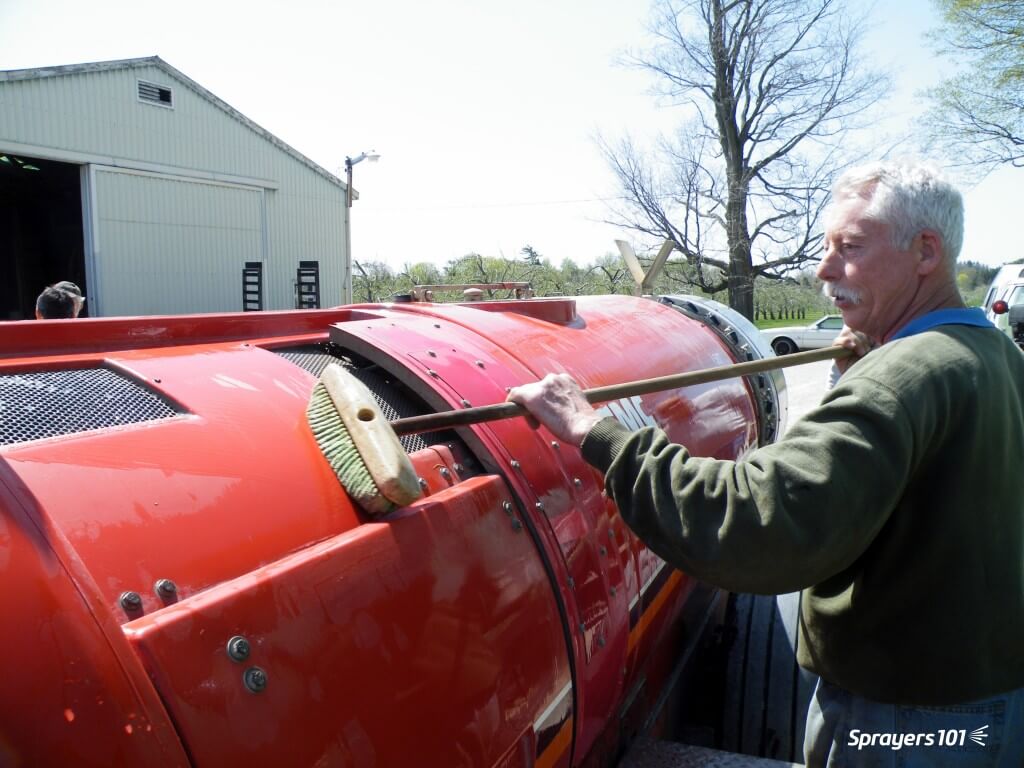
Keeping the airblast sprayer clean, inside and out, as part of the spray day. Ken Bell is pictured giving his FMC a bath. This picture was staged – he normally wears PPE and so should you.
Dr. Tom Wolf (Agrimetrix Research and Training), defines cleaning as two processes. Rinsing is the dilution of any remaining spray solution. Cleaning is rinsing with additional steps to decontaminate sprayer components (e.g. filters, nozzles).
Rinsing
1. Rinse ASAP
Don’t let residue sit in (or on) the sprayer, even if you plan to use the same product the next day. Multiple studies have shown that products adsorb onto, and absorb into, plastic and rubber parts. They form hard-to-clean residues when left to dry.
Think about cleaning oatmeal or egg yolk off dishes – it’s far easier if you clean them before they dry. Rinse right away, while the sprayer is still wet.
2. Minimize the volume remaining in the sprayer
Experience, sprayer math, and familiarity with airblast sprayer design helps minimize the volume remaining in the sprayer. Rate controllers and volume-monitoring systems (e.g. Ontario’s Accu-Volume) provide real-time feedback so the operator can speed up or slow down to empty in the right place. Minimizing any remaining volume makes rinsing far more effective.
Even an “empty” sprayer can still retain several litres of standing volume in the sump and lines. Operators should know this volume. Never Drive-and-Drain to empty standing volume onto the ground.
Standing volume from the booms allowed to drain to a holding tank via the bottom nozzles.
3. Dilute the remnant: The Triple Rinse
Rinsing the system multiple times with low volumes (aka The Triple Rinse) is more effective at reducing pesticide concentration than a single, high-volume rinse. See for yourself using this clever dilution calculator.
Once the sprayer is “empty”, use clean water to fill the tank to 10% of its capacity (or add 10 parts water to one part standing volume) for the first rinse. The use of such low volumes may not be possible with centrifugal systems where the tank must be filled above the top of the pump for priming. Know your sprayer design.
Agitate and circulate it through the entire sprayer for a few minutes. Spray out the rinsate and repeat the process two more times. Where do you perform this? Where does the rinsate go? Read on.
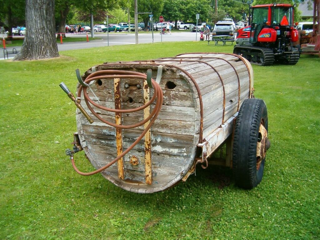
A wooden sprayer tank. You know that had to be tough to clean.
Where does the rinse water come from?
Nowadays, all airblast sprayers should include an onboard tank-rinse system consisting of a clean water tank and tank-rinse nozzles inside the tank. They may even include a pressure wand to rinse the exterior.
Sadly, most airblast sprayers do not have these features. But, aftermarket rinse kits are available. If you are considering installing a rinse system, check out the continuous rinse system.
Left- Product-pump-powered water tank, Right- external-pump-powered water tanks. Images from Paolo Balsari’s (DiSAFA) “Sprayer Cleaning: Importance and Phases” at AAB Sprayer Cleaning Workshop, Oberbozen, Italy. October 2019.The Hol features a separate 150 L tank to supply clean water to its automatic tank rinse system.
Alternately, the clean water for this process can be carried on a support vehicle or sourced from holding tanks strategically-located near the planting.
Where to rinse
Precautions must be taken to ensure rinsing is performed away from wells or open water. It is best to perform the triple rinse in the crop that was just sprayed. The dilute rinsate can be flushed through the lines and sprayed out through the nozzles onto the crop. You can choose to overspray treated areas again at a lower dose (label permitting), or use a hedgerow or target row that has been set aside for this purpose.
As regulatory agencies concerned with environmental contamination re-evaluate chemistries critical to horticulture, it becomes even more important for airblast operators to manage rinsate responsibly.
While it is best to rinse the sprayer exterior in the planting as well, most return to the farm. Too often, the entire rinsing procedure takes place on-farm, on crushed gravel. This creates point-source contamination: a leading source of off-target pesticide movement. Washings should be secured (e.g. on an inflatable or permanent loading/mixing pad.
Cleaning an airblast sprayer on an inflatable pad. Images from Victoria Nelissen’s (pcfruit, Belgium) “On-farm systems to avoid point pollution” at AAB Sprayer Cleaning Workshop, Oberbozen, Italy. October 2019.
In Europe, operators are encouraged to collect contaminated rinsate for safe disposal. There are four systems in use:
Bioremediation – Employs a bio-active matrix (E.g. Biobed).
Evaporation / Dehydration – Residue following evaporation is collected and disposed of (E.g. Heliosec).
Physico-chemical – A combination of filtration and active carbon.
A complete cleaning is required prior to long-term storage, or when residues from previous applications are known to cause physical or chemical antagonism with scheduled applications. Perform the following steps after a complete triple rinse:
One. Remove the suction and in-line screens. Remove nozzle strainers and nozzle tips. These will be inspected and cleaned shortly.
Two. Fill the tank about 1/2 full of water and add an appropriate tank cleaning adjuvant. For example, ammonia at 3%/100L water will raise the pH and helps remove those products whose solubility benefits from this. A detergent at 1.0 kg /150 L water will remove the oily layer formed by EC formulations. Commercial cleaners like All Clear or Cleanout conveniently combine these properties in one jug. Be aware that adding a surfactant or a commercial cleaner can generate a lot of foam, so have de-foamer handy.
Note: Ammonia cleaner products do not “neutralize” pesticides; they raise the pH, improving the solubility of some products. Do not use chlorine bleach! It is not as effective a cleaner as ammonia and can form chlorine gas when mixed with ammonia-containing liquids.
Three. Collect a bucket-full of cleaner solution from the tank. Using a brush, clean the suction and in-line screens, and the nozzle strainers and tips.
Four. Meanwhile, agitate and circulate it the cleaner solution through the entire sprayer for five to 10 minutes. Open and close any lines or valves during this process to ensure everything is exposed to the rinse.
Five. You might spray a small volume through the booms, but drain the vast majority through the plumbing system. Collect some for cleaning the exterior of the sprayer.
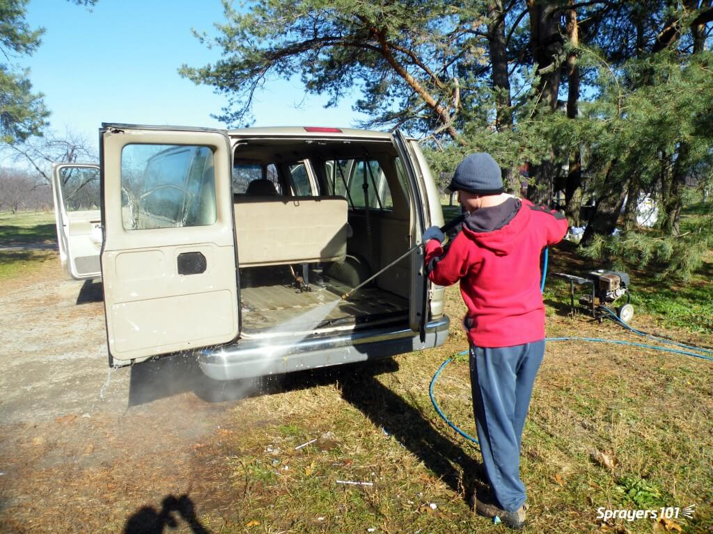
Six. Clean the exterior of the sprayer. High pressure washers and scrubbing with a push broom works well. Studies in Europe have shown the vast majority of residue is found on the sprayer head (i.e. fan outlet and boom area).
Pressure washers are handy tools on a farm, and they’re fun to use, too. However, they can cause a great deal of damage if they are used to wash delicate things like engine parts, electronics housings, or sealed bearings. Use caution when power washing an airblast sprayer.Relative external contamination on a low profile axial airblast sprayer. Image from Paolo Balsari’s (DiSAFA) “Sprayer Cleaning: Importance and Phases” at AAB Sprayer Cleaning Workshop, Oberbozen, Italy. October 2019.
Seven. Rinse it all off. Replace all parts unless preparing for long-term storage.
This article describes a method for assessing airblast sprayer coverage based on a protocol developed by Dr. David Manktelow (Applied Research and Technologies Ltd., NZ). It was co-written with David Manktelow and Mark Ledebuhr (Application Insight, LLC, USA). An older article describing canopy coverage assessment can be found here.
Why assess coverage?
Airblast sprayer configuration can require a lot of guesswork. There’s too much time between spraying and observing the results for operators to evaluate adjustments. They need timely feedback to assess the fit between sprayer and target.
Achieving adequate coverage of target surfaces (e.g. fruit, wood, inner canopy, etc.) is the basis of effective crop protection. Assessing coverage as soon as possible alerts the operator to correctable problems. The following three methods are helpful, but they have limitations.
The shoulder-check
Shoulder-checks can identify leaks and plugs, but operators cannot detect variation in flow from nozzle-to-nozzle (even when it’s over 50%). The vantage point also makes it difficult to determine if spray is passing under, over or through the target row. It is better to perform an inspection with the help of a partner outside the sprayer as part of a formal pre-spray check.
Shoulder-checks are fine for detecting plugged or leaking nozzles, but the vantage point makes it hard to discern much else.
Run-off
Unless specified by the pesticide label (e.g. drenching bark
with oil), spraying to run-off usually means excessive and non-uniform
coverage. It’s been demonstrated in trees and vines that when the outer canopy
begins to drip, the inner has only received about half the spray volume.
Efficacy trials confirm that spraying to run-off will provide protection, but it’s unnecessarily wasteful. Loses of 10-15% have been measured at the point run-off. Additional spray volume may increase coverage in the inner canopy, but the saturated outer canopy receives no additional deposit. The excess simply drips off. Further, there are potential phytotoxicity issues at the drip-points where residues concentrate as they dry.
Dripping is an unreliable coverage criterion because the threshold for run-off depends on the nature of the target surface (e.g. waxy, hairy, vertical) and the product formulation (e.g. oils, stickers, spreaders) and droplet size.
Run-off is not a reliable indication of good coverage.
Inspecting wetting and residue
Inspecting targets for wetting or residue can give a broad indication of whether a target received spray, but it’s hard to see on some plant surfaces. Dry fluorescent tracers and kaolin clay can help operators visualize deposits on actual plant surfaces, but they are messy, time-consuming and after-the-fact (i.e. too late too correct sprayer settings).
Helpful Tip: Look for residue on high-contrast infrastructure, like trellises or black irrigation lines. Remember, they are sill only subjective indicators.
The preferred method
Water sensitive paper
This method relies on water sensitive papers to help visualize spray coverage. The yellow side can resolve droplets >50µm in diameter, turning blue where it contacts moisture. With the aid of smartphone apps such as SnapCard (as of 2026, may no longer be available), or portable scanners such as DropScope, water sensitive papers can be used to characterize droplet density and droplet size up to 30% total coverage.
These surrogate surfaces do not show the spreading effects that can occur on plant surfaces (especially where surfactants are used). They also show lower deposits than leaves, which move freely in airblast air. Nevertheless, they give a useful indication of potential coverage.
To avoid fingerprints, wear gloves or handle them by the back and edges. They will slowly turn blue in humid conditions, so keep them sealed in their foil package when not in use. Packages of 50, 25x75mm (1×3 inch) papers are available online or from local agrichemical retailers for about $50.00.
Preparing water sensitive papers
You will need ten pushpins (five dark coloured, five light coloured), ten papers and a resealable plastic bag. The following process may seem like close-up magic but with practice you can quickly prepare multiple sets of papers.
Remove eleven papers from the foil package.
Stack them yellow-side-up and flip the top paper over.
Using the flipped paper, carefully fold the stack in half. Now ten are folded yellow-side-out.
Expose 1/4 of the middle paper. Pinching the stack firmly will flex it and give support as you pierce the corner with a pushpin (twist as you push).
Use the pushpin as a handle to slide it from the stack and drop it into a Ziploc bag. Repeat the process for the remaining nine papers (return the outside one to the package for later use).
They will remain viable in the sealed bag for several days before they are used in the target canopy. Once placed in the canopy, ten folded papers provide 20 target surfaces.
Six steps to preparing and attaching water sensitive paper.
Placing the papers
To avoid boundary effects, don’t place papers in the periphery of the planting. To make sure the sprayer is up-to-speed and the canopy is not overly exposed to wind, go a short distance into the target row and pick a representative tree or vine. The pins will hold the papers to stems, twigs and leaf petioles. Shadowing from leaves is inevitable, but try to avoid placing them up against fruit, leaves or wood. Relative placement within the canopy depends on canopy size:
Small canopies
For grape, pin five dark pins into stems next to inner bunches deep in canopy. Pin the five light pins around the outer bunches, oriented with one side of the paper exposed to the sprayer. When you stand back, it should be hard to see the inner papers.
Similar positioning can be used for berry canes and bushes. Pin five dark pins in the inner canopy, spanning the height but oriented randomly. Pin five light pins in the outer canopy, spanning the height but oriented with one side exposed to the sprayer.
Helpful Tip: Keep the papers clustered in a 1-2m (6 ft) row and tuck the Ziploc bag into the dripline to mark where they are. They shouldn’t take long to find after spraying.
Medium canopies
For high-density orchards and larger trellised canopies, a ladder might be required. Pin five dark pins in the inner canopy, spanning the height but oriented randomly. Pin five light pins in the outer canopy, spanning the height but oriented randomly
Large canopies
For large trees (e.g. tree nut, citrus, sour cherry), a
modified approach is required. Instead of dark pins, use sections of plastic or
galvanized conduit. Note the wire clips developed to affix papers to the
conduit in the image below. Any method of firmly affixing the papers is
acceptable.
Stand at the trunk and raise the conduit section by section to
reach the full height of the canopy. Attach five papers as you erect the
conduit mast with one at the top, one at the bottom and the other three evenly
distributed. A wrap of electrical tape may be required to help hold sections
together. Then, pin five light pins in the outer canopy, oriented randomly and
spanning as high as can be conveniently reached.
Helpful Tip: Tie a length of flagging tape near the papers to make them easier to find and replace between assessments.
Use lengths of metal or plastic conduit to create a mast that can span the height of large canopies. Distribute papers evenly along the length as it is assembled.Larger trees, like nuts, citrus and sour cherry make it harder to assess all canopy positions (and to spray them).
Spraying
It is preferable to spray clean water from a rinsed sprayer, but you can assess coverage during a chemical spray if label restrictions permit re-entry. Always wear PPE when required.
Spray the target row as you normally would (e.g. both sides, alternate row middle, multiple rows) in weather you would normally spray in. Retrieve the papers as soon as they are dry enough to handle.
Complete the top section, being sure to describe the sprayer set-up, application volume and weather conditions at the time of spraying. Either staple or glue the recovered papers to the form. Try to arrange them relative to their original positions in the canopy.
Helpful Tip: Glue sticks work very well but avoid lumps that will show through.
What do you think of the coverage seen on the 20 surfaces in this example? Seven of the 20 surfaces (35%) show almost no deposit, and 10 (50%) have visibly low numbers of relatively large droplets – that is usually an indication of inadequate coverage.
Assessing each paper
Research and experience suggest that a droplet density of about 85 Fine/Medium-sized droplets per cm2 and about 15% overall coverage is adequate for most foliar insecticides and fungicides. With experience, this can be judged by eye. Note: only 80% of all papers require this minimal threshold coverage. This is described later in the article.
Helpful Tip: It is sometimes helpful consider the amount of yellow left between the blue.
Grade each of the 20 surfaces as (E)xcessive, (A)dequate or (I)nadequate by circling the corresponding letter on the form.
Adequate satisfies minimal coverage.
Excessive will provide crop protection, but often indicates unnecessary waste.
Inadequate includes non-uniform coverage and nil coverage.
There are a few notable exceptions:
Make allowances for papers where potentially Adequate coverage has been masked by an adjacent obstacle (see paper number 5, below).
Finer sprays will have very high droplet counts and less volume. Paper number 6 (below) would be Inadequate for a high volume, dilute application. However, this uniform distribution is Adequate for a low volume, concentrated application (e.g. mistblower).
Coarser sprays may have lower droplet counts or coalesce into blobs (see paper number 2, below). Focus on even distribution and the 15% overall coverage.
Unless using a scanner, visually assessing papers can be subjective. Rely on droplet density, overall coverage and the product’s mode of action when making a determination. Paper number 6 is Adequate for a mistblower due to the high droplet density and uniformity.
Assessing the canopy
Spray coverage can be highly variable. This method employs 20 surfaces and semi-random orientation to offset some of that variability. Minimal coverage (i.e. Adequate and Excessive) should be achieved on 80% of the papers.
Complete canopy coverage is not required. Studies in New Zealand winegrapes showed a direct correlation between the percentage of Inadequate papers and levels of bunch botrytis. Disease levels increased as the number of Inadequate papers increased over 20%.
Watch for the following in the overall coverage patterns:
Clustered gaps in coverage
This occurs when spray fails to reach the targets. Gaps often occur in the top third of large canopies and deep in dense canopies. This could indicate problems with air speed/orientation, dense canopies, or inadequate flow from corresponding nozzle positions.
Uneven coverage
In medium and large canopies, the outer canopy often receives more spray than the inner canopy, and this may be unavoidable. Be aware that an even distribution of droplets on poorly covered surfaces could indicate underdosing relative to bluer surfaces.
Run-off
This is typical in the outer portion of large and/or dense canopies during high volume (i.e. dilute) applications. More than 50% of surfaces will be thoroughly wetted; Papers will curl, and blue dye may drip off. Unless specified on the product label, it is excessive for foliar applications, but may be unavoidable.
In low volume (concentrate) applications, run-off could indicate poor nozzle distribution or tight alleys. It is generally undesirable and indicates waste.
Improving canopy coverage
This is an iterative process requiring a few attempts before coverage is improved. Try to identify the most limiting factor, make a single adjustment, and then reassess. Consider factors such as travel speed, sprayer air output, nozzle rates and overall spray volume. Also consider canopy management and weather conditions.
When water sensitive papers are prepared in advance, each assessment should take two people about 20 minutes. Compare assessments side-by-side. When one set of papers appears “bluer” than another, measurements have shown it represents >20% difference in actual canopy deposits. This is very likely to have a biological impact.
This small investment of time and money can return better crop protection, greater efficiency, and confidence that the airblast sprayer is doing the job.
Real world example
While in Mildura, AU, we were invited to optimize a Silvan wrap-around multirow sprayer in box-hedged grape. Originally an air-shear sprayer, it was converted to employ air induction hollow cone nozzles (six air outlets per row-side, 550 L/ha [50 gpa], 8.5 km/h [5.3 mph]).
A Silvan wrap-around multirow sprayer in grape.
We noted that the outer arms were 2.8m (9 ft) from the canopy, and the inner arms were 2.1m (7 ft). We brought them in to 2.1m and employed the previously described assessment method to establish a baseline for comparison (see assessment number 1).
The outer arm was brought in until nozzles on both arms were equidistant from the target canopy.Assessment Number 1 (Left). Mostly Inadequate.
Watching as the sprayer passed, we noted the canopy compressed rather than ruffled. This was likely caused by the air outlets being perpendicular to the canopy. When the canopy closed, air and spray were deflected rather than allowed to penetrate. There were also V-shaped plates in each air outlet left over from its days as an air-shear sprayer that deflected the air in strange ways.
We angled the air ducts and decided to remove the 80 degree air induction nozzles. There have been recent reports of improved grape canopy penetration from the new Arag 40 degree hollow cones, so we tried them. Unfortunately, we chose nozzles with too high an output and the operating pressure dropped below 3 bar (44 psi). With poor atomization, the resulting coverage was still poor. Note the finer droplet size from the switch from air induction to conventional hollow cones (see assessment number 2).
Assessment Number 2 (Middle). Finer droplets and still mostly Inadequate.
Time was limited, so we made two significant changes before the final assessment (yes, we know we said one at a time). First, we rearranged the nozzles. 60% of the total volume was from 40 degree nozzles aiming finer droplets at the fruit zone. The remaining 40% was from 80 degree A.I. nozzles aiming coarser, drift-resistant droplets at the upper canopy. This also restored our working pressure.
Then we noticed the position of the nozzles relative to the air outlets. The air preceded the nozzles, which would leave the droplets trailing behind the air rather than carried into the canopy. We turned the nozzle/duct assembly 180 degrees, so the nozzles preceded the air outlet. The final assessment showed greatly improved coverage (see assessment number 3).
Flipped nozzle/air duct assemblies so nozzles preceded air to better entrain the spray. Assessment Number 3 (Right). Far better coverage, but still room for improvement at the top of the canopy.
The sprayer operator reaped immediate benefit from the two hours of assessment and reconfiguration and has continued to use this method to optimize the match between his sprayers and crops throughout the season.
Agricultural products are formulated to be as emulsifiable as possible, but many do not mix well in water. They contain elements that do not dissolve (e.g. wettable powders), or they may be petroleum distillates (e.g. emulsifiable concentrates). Other products are heavier than water and form precipitates (e.g. fertilizers and powdered metals like copper). Consequently, good agitation is very important.
Effective agitation requires water to “sweep” the bottom of the tank so that any precipitated material is picked up and re-mixed. Turbulence is often not enough. If there is too little agitation, the pesticide will be applied unevenly and not always at the required rate. If there is too much agitation, the pesticide may foam (which can be controlled using anti-foamers) or cause an invert emulsion (a gel). There are two types of airblast sprayer agitation: Mechanical and Hydraulic (learn about pros and cons here).
Mechanical Agitation
Mechanical Agitation is produced by paddles that are attached to a shaft mounted near the bottom of the spray tank. While effective, this system cannot always sweep the very bottom of the tank, so there is always some material that precipitates out of reach. Are your nozzles and screens plugging frequently, and is there “sludge” left at the bottom of the tank after spraying? You may have an agitation issue.
Note the two paddles set at 90° to one another on the mechanical agitation shaft in this very cool “cutaway” Turbomist sprayer.
Hydraulic Agitation
Hydraulic Agitation is accomplished by returning a portion of the pump output to the tank. Cylindrical and oval tanks are the ideal configuration for the sparging (i.e. rinsing) type of hydraulic return agitation system. This system consists of a tube located longitudinally along the wall of the tank, with volume booster nozzles aimed at the centreline so they sweep across the bottom. Volume booster nozzles take a small amount of water pumped into their venturi chamber and create a vacuum that draws three to four times that volume from the surrounding water and expels it out the end.
For hydraulic agitation to the effective, the agitator nozzle(s) should be fed by a dedicated line from the pressure side of the pump (not the pressure regulator). They should have a valve to throttle the flow or completely shut it off to prevent foaming.
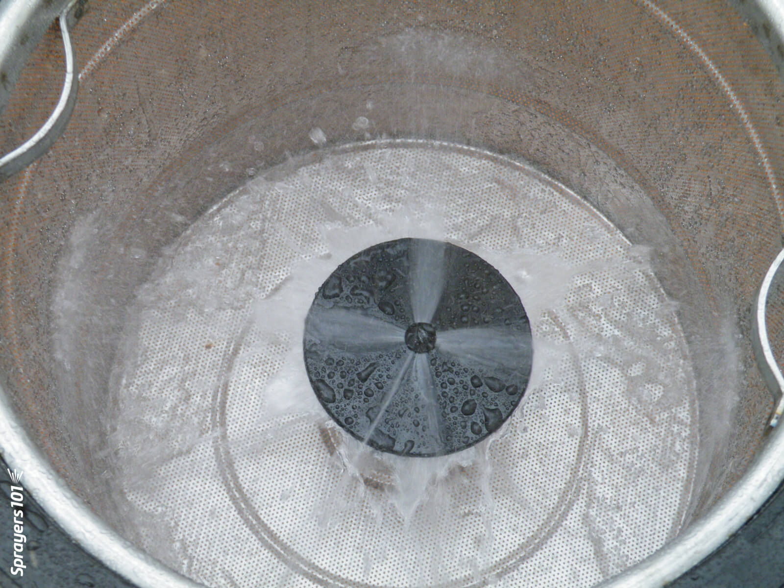
A mixing nozzle in the basket of a Hol sprayer.With enough pump capacity, a hydraulic return in the tank basket is a great way to agitate as you mix. A return in an older FMC.
Adding Water Soluble Pouches
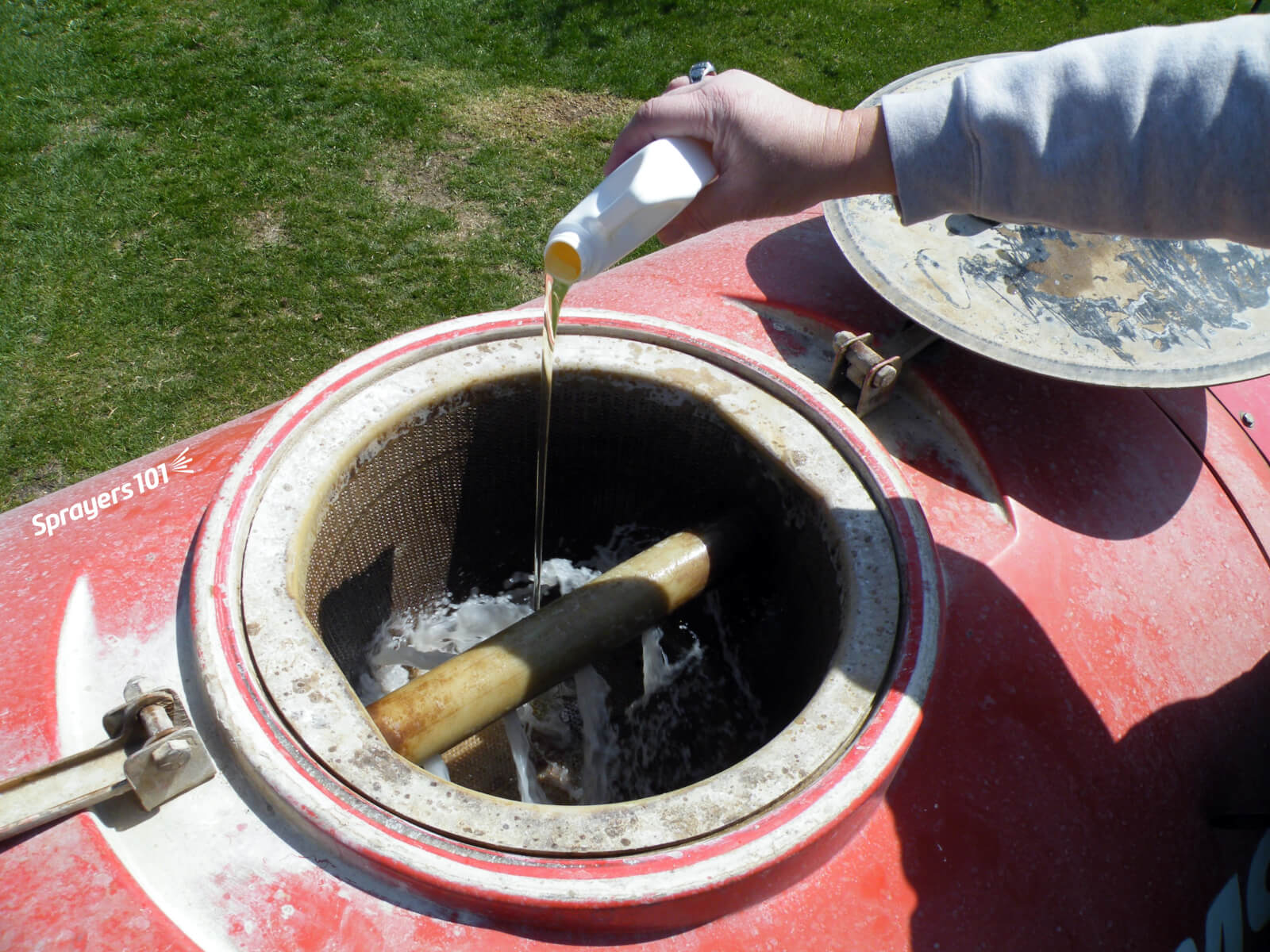
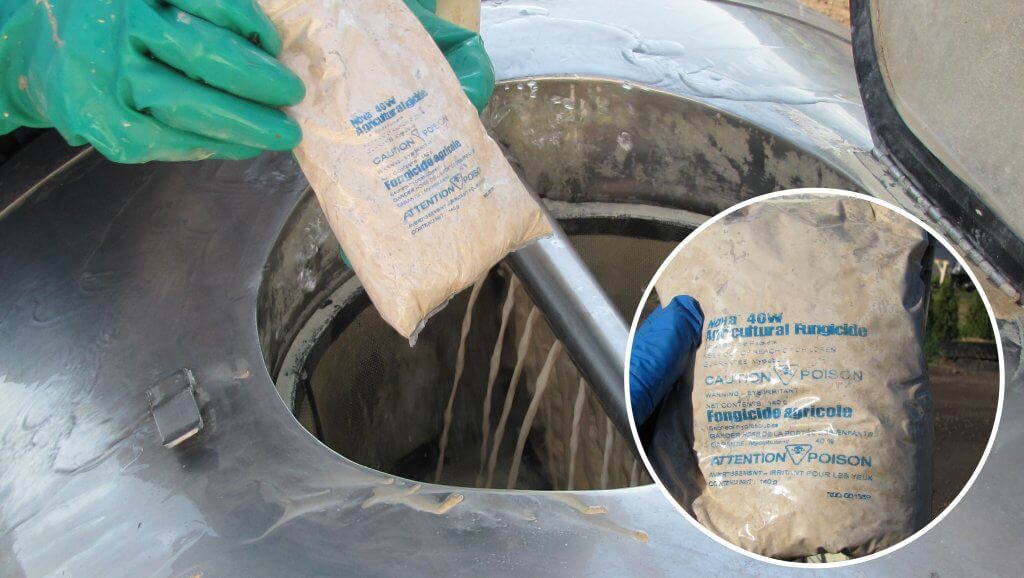
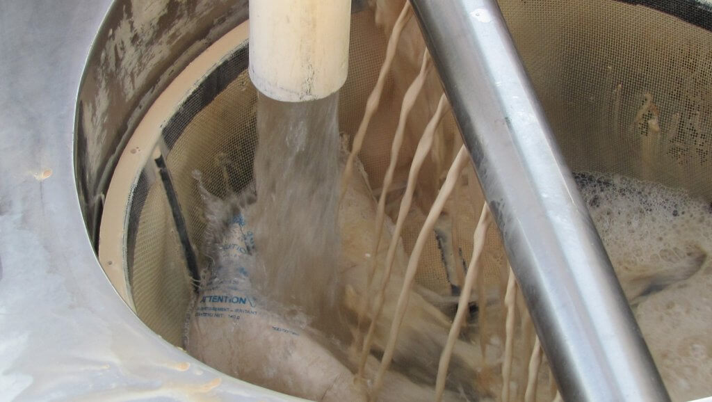
Adding pesticide to the sprayer may not always be straight-forward. Many airblast operators, for example, place dissolvable pouches in the basket so they can be broken up by the hydraulic return, or the fill water. But fill water often splatters out of the basket, and the bags can burst open, releasing product into the air. This creates unnecessary contamination and both inhalation and dermal exposure concerns.
Photo credit: Mario Lanthier.Photo credit: Mario Lanthier.
Some elect to temporarily remove the basket and add the pouches to a half-full tank with the agitator on. However, the pump can suck in the partially dissolved bag which then coats the intake screen. This is exacerbated when the fill water is cold. I know of one operator that had to rebuild the pump because the Viton seals burned out. This operator now adds pouches to the basket while standing upwind and away from potential splatter. Or, they mix a pre-slurry.
Mixing a pre-slurry requires the operator cut the bag into a five or 10 gallon bucket filled with water and to incorporate using a paint mixer. However, mixing a pre-slurry increases the chances of dermal exposure, inhalation and point-source contamination. Dissolvable bags were intended as a form of closed transfer, which is a good idea. Mixing a pre-slurry defeats that intent.
And so, for all these reason, I don’t feel dissolvable pouches are a good formulation choice. If possible, select product formulations that do not cause possible filling issues and better match the capabilities of your agitation system. Always choose the safest and most effective filling method for your sprayer design.
On a trip to Mildura, Victoria I met Matthew McWilliams, Director at Interlink Sprayers. His passion for innovation was exciting. He described Interlink’s history of near-annual design improvements, each of which made the last generation of sprayers look a bit passé. Continual improvement means spending a lot of time educating and upgrading customer’s sprayers, but that level of support is worth it. Their strategy of drawing from leading international designs and improving on them has led to a unique axial fan assembly that boasts impressive benefits for those spraying large canopies.
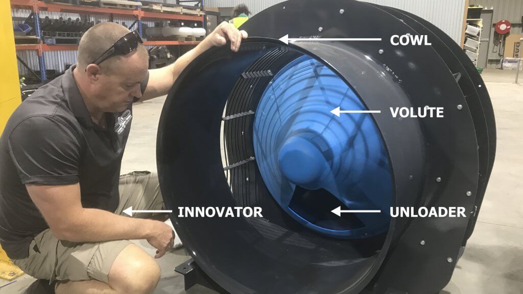
A man and his fan housing.
Matt explained a problem common to any axial fan: they hate back-pressure. When an axial fan blows air against a volute, which redirects the air laterally, the back-pressure acts like an air break. It pushes back against the fan, flexing the blades, reducing output volume and reducing efficiency.
In an effort to relieve some of this pressure, Interlink cut a hole in the volute (called an “Unloader”). Venting reduced the pressure and increased efficiency significantly. It did something else, too, but we’ll get to that later.
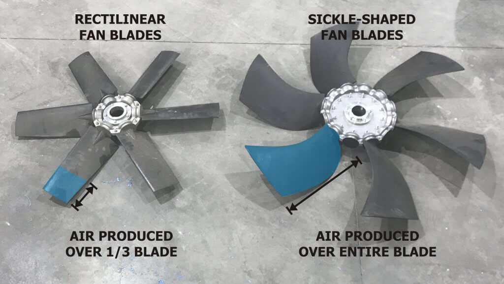
This success led them to reconsider fan blade design. Classic, rectilinear fan blades are inefficient. They only produce air over the last 1/3 of their length. Using computational fluid dynamics, they modelled an efficient sickle-shape that creates pressure over the entire length. This means it can produce as much volume as a rectilinear blade, but with fewer revolutions.
The difference between rectilinear and sickle-shaped fan blades.
When the new blades were combined with the Unloader, they were able to move the fan closer to the volute and make the cowl longer. A less-exposed fan is not only safer, but its proximity to the volute increased efficiency.
The result was a 2.5x increase in pressure and a concomitant 30% savings in horsepower. In other words, while similarly-sized sprayers were using 25 L (6.5 US gal.) of fuel per hour, they created the same air volume and speed using 17 L (4.5 US gal.) fuel per hour.
But why stop there?
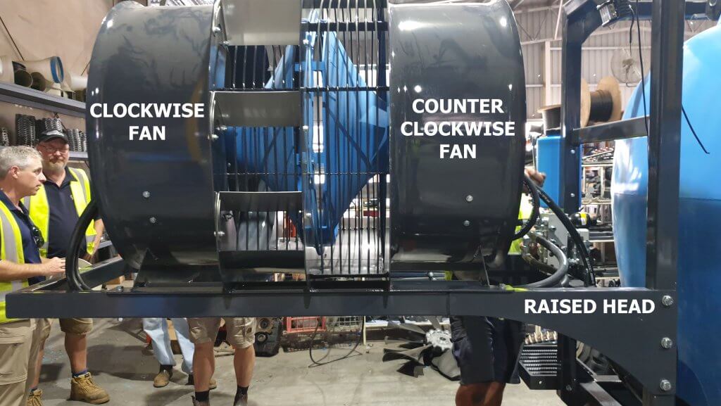
Nut orchards in Australia and the US can grow up to 21 meters (~70 feet). A low-profile axial sprayer must produce a great deal of air volume to both penetrate the canopy and reach the top. Increasing fan diameter can help, but perhaps two fans are better? Air-O-Fan has their twin-fan system, where two shaft-driven fans with reversed blade pitches produce high-volume turbulent air. Interlock decided to try it.
Hydraulics permit the twin-fan head to be raised off the ground.
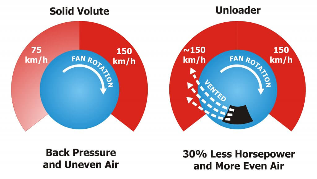
When two hydraulically driven fans were placed back-to-back (spinning counter to one another) the Unloaders did something Unexpected. Normally, an axial fan blowing against a volute creates deflection, causing higher speeds on the downward side of the fan. Most sprayers use vanes to correct this, but they cause back-pressure. Serendipitously, when placed back-to-back, the pressure vented through the Unloaders was reclaimed on the upward side of each fan, equalizing airspeed across the outlet.
The air vented through the Uploader evened-out the airspeed.Computational fluid dynamics demonstrate even air-speed and volume on both sides of the sprayer.
And there’s still more. Since this counter-rotation twin fan design is hydraulically driven, it is not restricted by a shaft. This allows the head to be lifted off the ground. Quite often in large orchards, air and nozzles are aimed too low, wasting spray below the canopy. Lifting the fan and nozzle banks brings everything closer to the top of the canopy; a notoriously difficult target to reach. It also reduces the level of dust and detritus stirred up from the canopy floor. Operators reported that the elevated fan head helped keep fan intakes and radiators (required on Australian airblast sprayers) clear of debris.
This low-profile axial airblast fan is a refreshing new approach to a design that has seen only marginal improvement over the last 20 years. Given the pace of innovation in Matt’s factory, I’m sure the next set of improvements will be in place by the time this article is published.
Excepting air shear and centrifugal style nozzles, most airblast sprayers employ nozzle bodies designed to except hydraulic nozzles distributed evenly along the booms. Nozzle caps compress the nozzle against the body to force the spray mix through the nozzle orifice. Nozzle bodies are not all created equal.
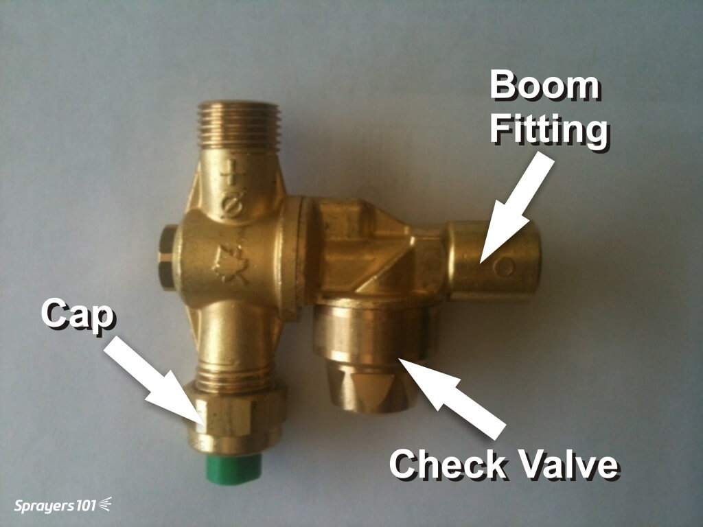
Double Outlet Roll-Over Nozzle Bodies
Double outlet roll-over bodies (pictured below) allow the operator to quickly switch between two nozzles mounted in each position. This is convenient when alternating from dilute to concentrated applications, or changing the spray distribution from block to block.
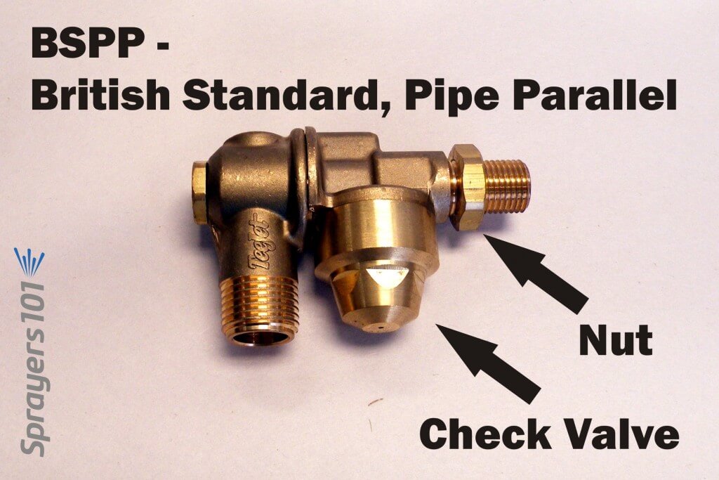
A typical brass roll-over style nozzle body with cap and check valve.
The roll-over feature can act as a shut-off and facilitate fine-tuning the orientation +/- 15° from centre. When roll-overs are new there is an audible ‘click’ when they reach 15° to alert the operator that turning them any further will interfere with flow. This feature fails as bodies wear.
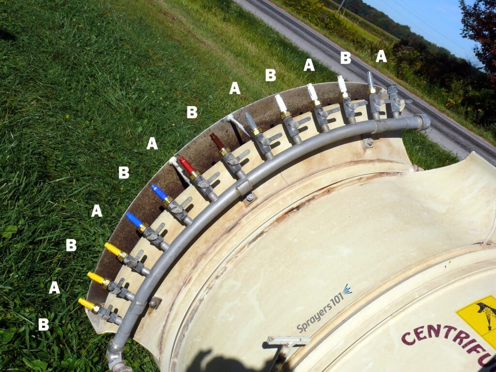
Single Nozzle Bodies
Some sprayers employ single nozzle bodies featuring screw or lever-style quarter-turn shut-offs. Some sprayers, like the Turbomist featured below, double the density of the bodies along the boom, arranged in an alternating A-B pattern. The operator shuts off each alternate nozzle, perhaps using the A’s for dilute and the B’s for concentrate applications. The density gives the operator the ability to “double up” in positions along the boom if more spray is required.
Some sprayers do not use double outlet roll-over nozzle bodies. Instead, they double the density of single bodies along the booms for use in an alternating A-B pattern.
Still others may affix the nozzle bodies to the deflectors (like the Air-O-Fan below), permitting the operator to orient the air and nozzles at the same time.
The Air-O-Fan offers double-density by affixing two single nozzle bodies to each air deflector. The operator aims air and nozzles simultaneously and can select flow combinations using quarter-turn shut-offs.
Check Valves
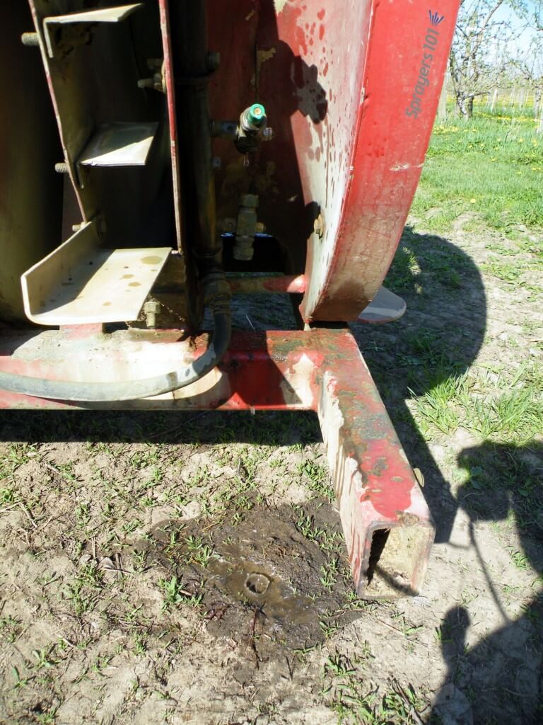
In my opinion, it should be mandatory for nozzle bodies (or at least booms) to have diaphragm check valves. When pressure drops below ~15 psi the valves shut to prevent the boom from draining (see image below).
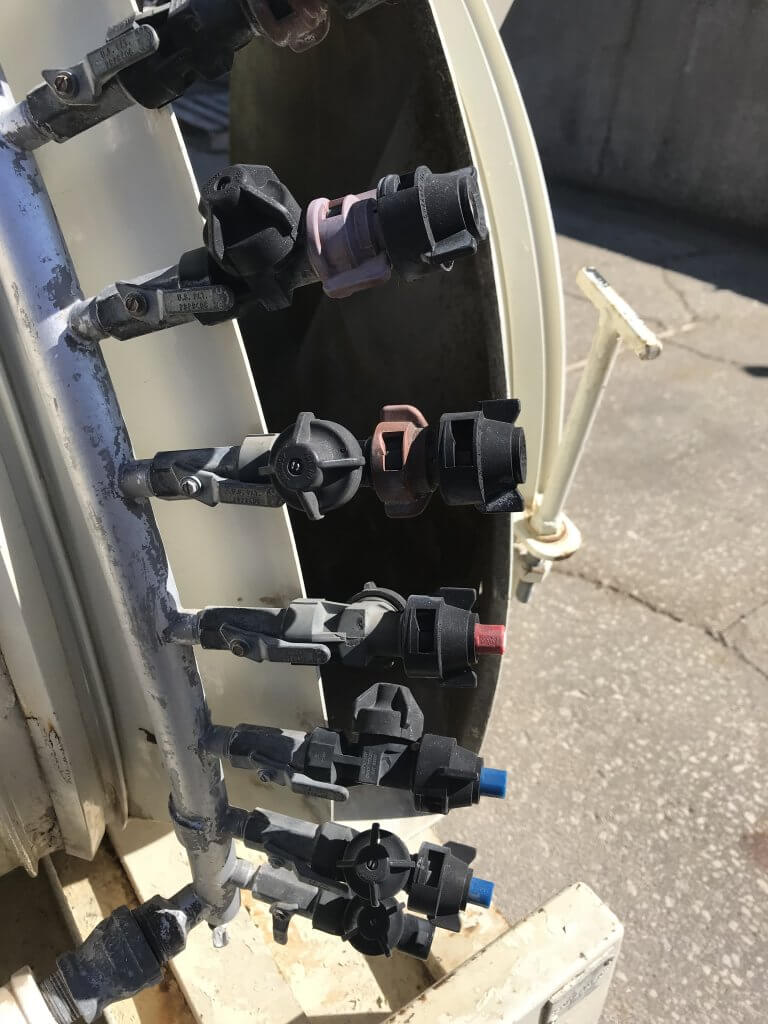
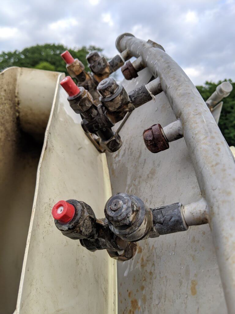
An older FMC with nozzles bodies that do not have check valves. Once the pressure is off, the booms drain through the lowest nozzle. This is a waste of pesticide and unnecessary environmental contamination.
Booms don’t just drain in the yard. Operators shut off the outside boom when turning at the end of a row. Without check-valves, the boom drains through the bottom nozzle, wasting pesticide and causing repeated and unnecessary point-source contamination. Further, it takes a moment for the boom to refill, meaning the top nozzles may not be spraying at the beginning of each row.
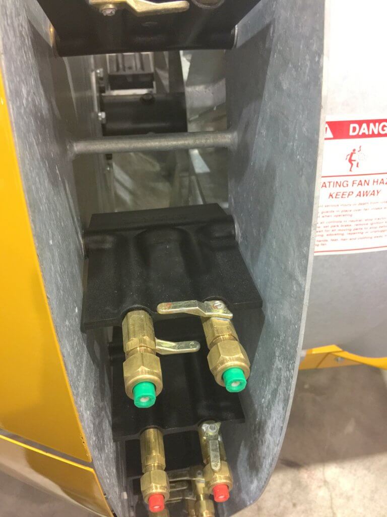
You may be tempted to purchase mesh nozzle strainers with built-in ball valves. They can work as an alternative to integrated nozzle body check valves, but they plug and fail with irritating regularity. The image below shows a creative method for installing check-valves on single nozzle bodies. The nozzles protrude and the check valve seems too close to the shut-off, but reputedly this works.
An example of retrofitting diaphragm check valves on single nozzle bodies.
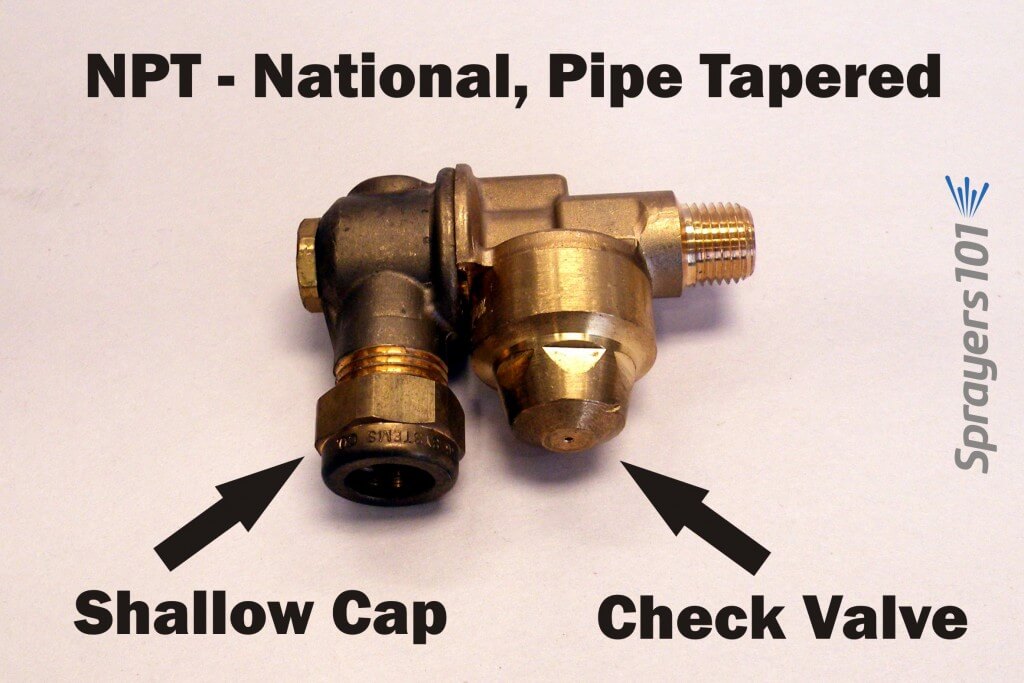
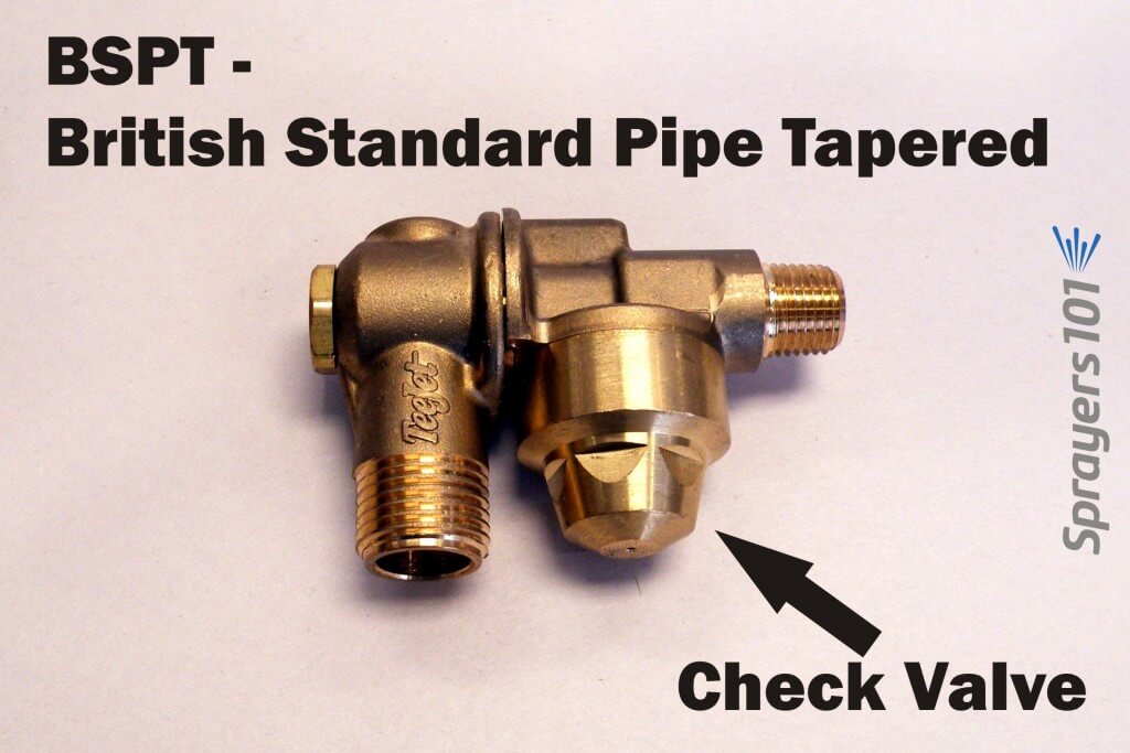
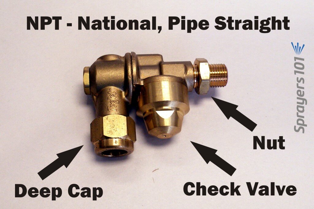
Thread Types
In North America, you will encounter four inlet thread types: NPT, BSPT, NPS and BSPP.
National, Pipe Tapered (NPT) single-sided, brass roll-over nozzle body with check valve. Note the shallow cap pictured here.British Standard, Pipe Tapered (BSPT) single-sided, brass roll-over nozzle body with a check valve.National, Pipe Straight (NPS) single-sided, brass roll-over nozzle body with check valve. Note the deep cap pictured here.British Standard, Pipe Parallel (BSPP) single-sided, brass roll-over nozzle body with a check valve.
The inlet thread sizes available are 1/4” female, 1/4” male and 3/8” male. 1/4” female is not available on the NPS or BSPP inlet thread types. If you are considering installing new roll-over bodies, know your boom’s thread type. The retrofitted Turbomist below, for example, required bodies with female fittings.
A retrofitted Turbomist with check valves and female double outlet roll-over bodies.
Molded Nozzles
Another reason for installing new bodies is to convert from disc & core combination nozzles to single-piece, molded nozzles. They may not fit existing nozzle bodies. Check the diameter of the body outlet (where the nozzle rests) and the outlet cap (which compresses the nozzle against the body outlet). Your sprayer may currently use an unusual-diameter nozzle, like older FMC disc & whirls or European large-diameter pink ceramic disc & cores. Today’s ISO molded nozzles won’t fit in those bodies, so you’ll need to replace them.
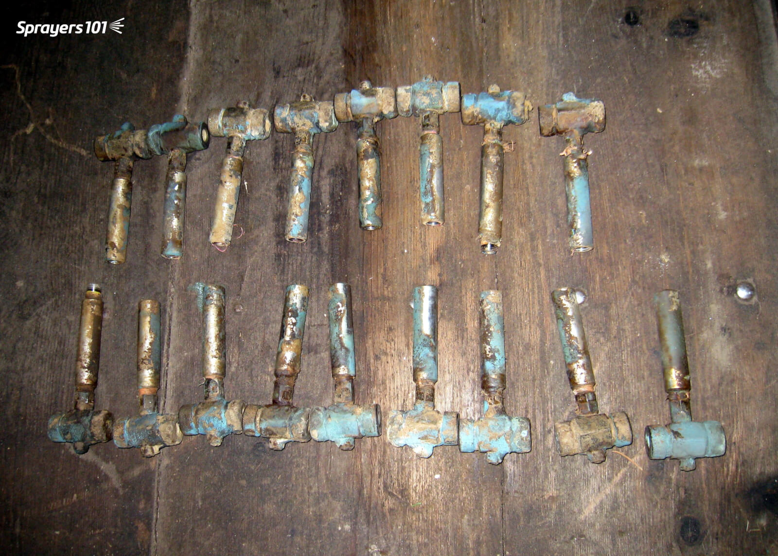
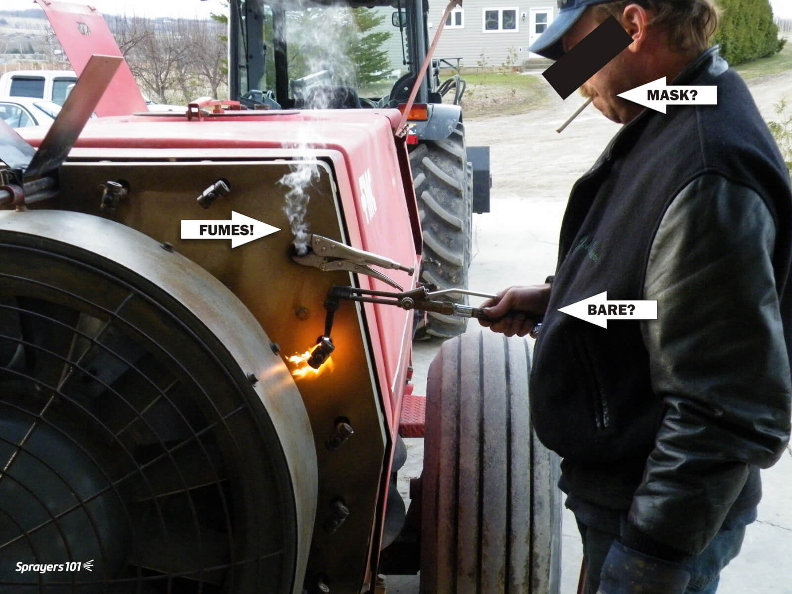
Old roll-over bodies without check-valves. These were removed to make way for better bodies.Older nozzle bodies can seize in the boom, requiring novel approaches to removing them. In this case, the mechanic is heating the fittings using “the blue wrench” to loosen them. If you do this, do not do what this mechanic did. Operate in an open space using gloves and a respirator. Years of residue build-up should be anticipated and respected.
Be aware: that unlike disc and core, molded nozzles protrude and may hit the edge of the sprayer duct when rolled over, preventing them from turning freely
Nozzle Body Caps
Nozzle bodies DO NOT come with the nozzle caps; they are specific to the nozzle type and must be ordered separately. This was an unpleasant surprise the first time I ordered a set of bodies.
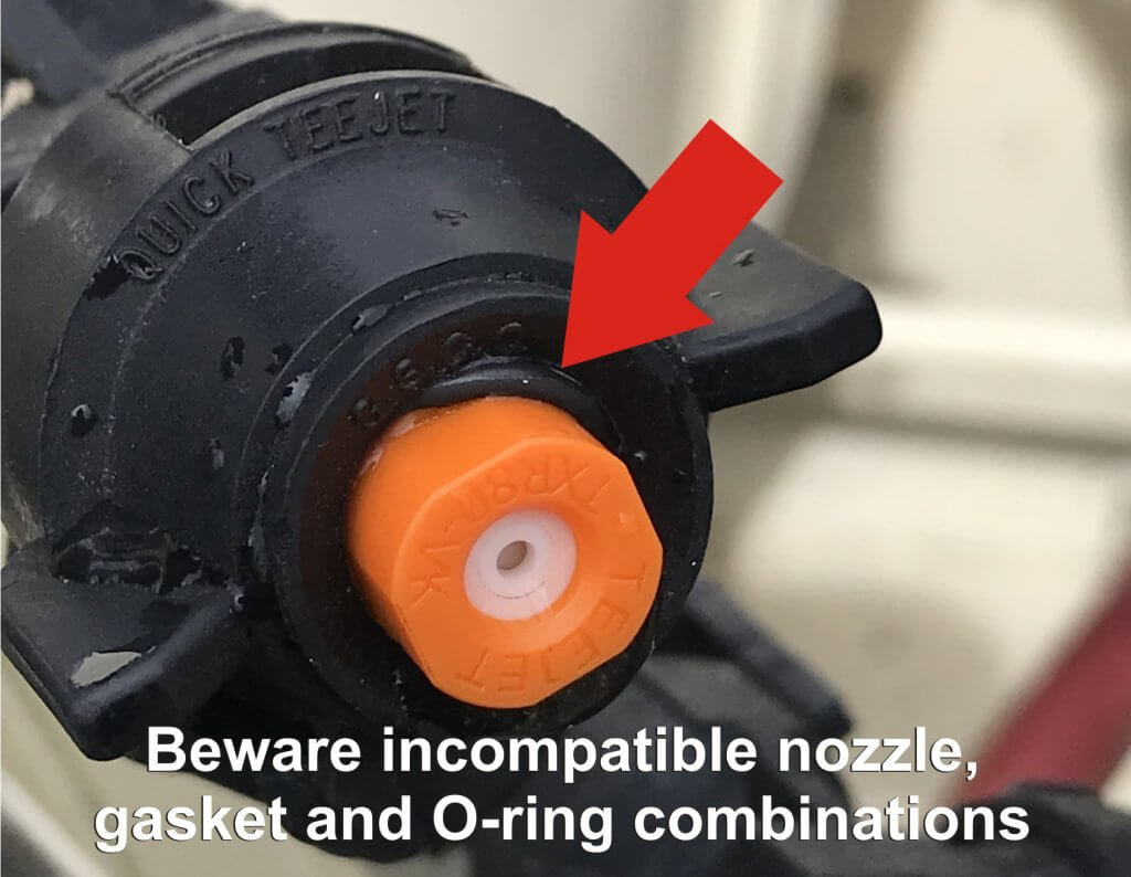
The standard caps are threaded brass hex nut-style but there are also nylon wing-style caps that don’t require a wrench. Beware converting to quarter-turn systems for airblast sprayers. It can work, but nozzles may require additional gaskets and O-rings… and even then are known to leak if the cap diameter is too large (see below):
Airblast pressure often exceeds 100 psi and can force the O-ring off the molded nozzle and cause leaks.
Be aware: North American nozzle caps might not fit imported European bodies, and European nozzles might not fit North American cap diameters. The LipCo sprayer is one such example.
Regarding the cap depths, sprayer operators must consider the how much “stuff” is between the nozzle body and cap. Gaskets, spacers, O-rings and strainers take up room that may warrant a deeper cap. Perhaps most critical is the nozzle itself. For example, brass disc-core are quite thin, but ceramic are much thicker. They require different cap depths.
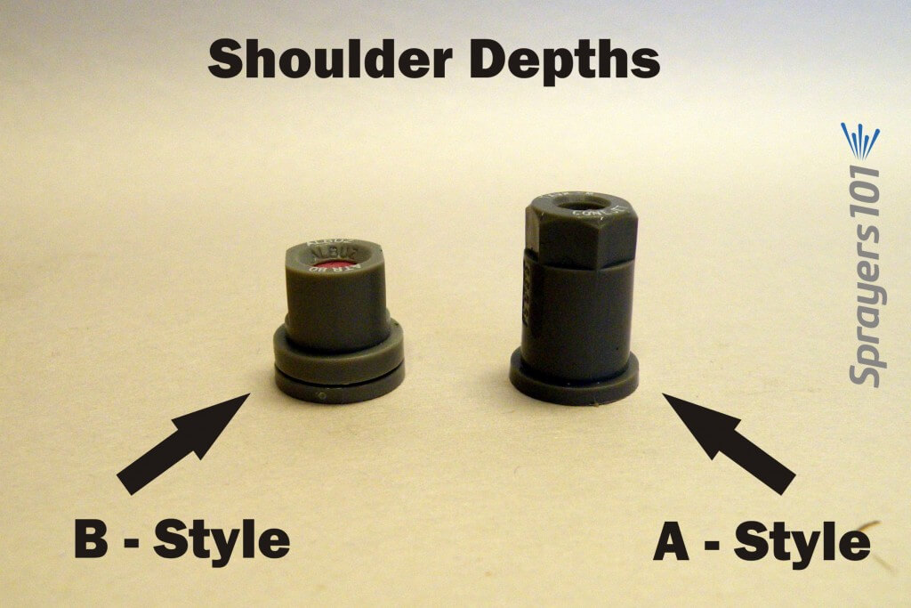
TeeJet’s molded cone nozzles come with an ‘A’ (Thinner) or ‘B’ (Thicker) shoulder. The shoulder is the lip around the nozzle base that is compressed against the nozzle body outlet. The B-shoulder is the ISO standard, and is preferred (see below). Shallow caps may not thread onto a nozzle body using a nozzle with a B-shoulder. Deep caps may bottom-out before compressing a nozzle with an A-shoulder, creating leaks. Be sure to note in the nozzle catalog which caps are recommended for the nozzle.
Molded cone nozzles come in the thin shoulder (A-style) or thick shoulder (B-style) varieties. The B-style is the ISO standard and is preferred.
Nozzle Strainers (aka Filters)
Before we wrap up, here’s one more look-out. As mentioned, the nozzle strainer shoulder takes up some room between nozzle body and cap. It turns out there can be another concern.
A hop grower contacted me. He had installed new nozzle bodies on his sprayer. He’d taken into account the shoulder depth and the cap depth. So why were his nozzles plugged? And why when he loosened the cap to finger-tight did they spray, but leak?
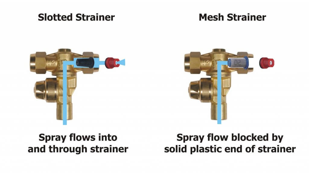
We tried gaskets, O-rings, different cap depths and new nozzles – but no change. That’s when we noticed one side of the roll-over body had a plastic slotted strainer and the other had newer mesh strainer. The mesh strainers were longer and terminated in a disk of solid plastic. When we swapped the two strainers, we had flow! We realized the longer mesh strainers were being compressed against the orifice in the nozzle body, acting like a cork in a wine bottle.
I prefer slotted over mesh because they are a bit more forgiving with dry formulations and hard water residue, but perhaps more critical is that they aren’t long enough to block the flow.
Be aware that some strainers may be long enough to block flow in the nozzle body.
Take Home Tips
If you are considering installing new nozzle bodies:
Confirm the male or female fitting and thread type of your boom
Ensure bodies have check valves
Ensure roll-overs and check valves clear any obstructions with nozzles in place
Know the nozzle type you intend to use, and ensure cap diameter is appropriate
Know whether you will use gaskets, o-rings, spacers and strainers, and confirm the cap depth will accommodate everything.
Be certain the strainer you choose isn’t so long that it interferes with flow.
Consider buying a single nozzle body to install as a trial before buying an entire set of replacements.