Category: Spray Basics

  • Calibrating a Plot Sprayer for Airblast Crops

    Calibrating a Plot Sprayer for Airblast Crops
    The calibration of handheld plot sprayers is an important part of agricultural research, and this article already covers all the bases… as long as you are spraying broadacre or row crops. But what happens when you are trying to emulate an airblast sprayer and treating a tree, bush, cane or vine?

    The key difference is that spraying a two dimensional area requires the operator to pass the boom over the target at a uniform height and pace to achieve consistent coverage. But, a three-dimensional target requires the operator to circle the target, or spray from both sides, until it has received the required dose (or volume).

    In order to scale down a typical airblast carrier volume for small plot work, we need to know three things:

    1. The area you wish to treat (e.g. bush, grape panel, tree, etc.), including it’s share of the alley (in m2).
    2. The emission rate from the calibrated plot sprayer (in US gal./min.)
    3. The airblast carrier volume you wish to scale down (e.g. L/ha).

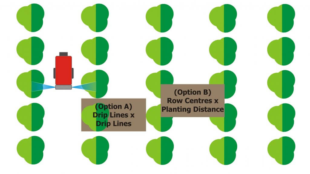
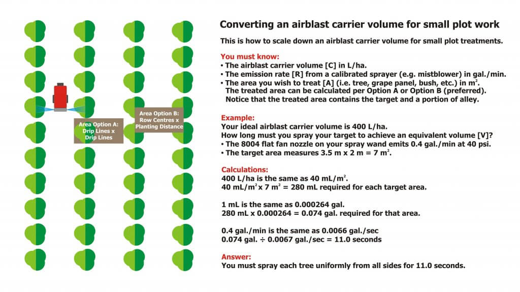
    The illustration below shows two options for calculating the treated area. Option A requires you to measure from the outermost edges of the canopy (imagine if the canopy was wet and dripping – the dripline is that outermost point). It is less consistent than the preferred Option B, where the area is determined from row centres and planting distance.

    Two options for scaling down an airblast carrier volume for small plot work. Both produce the same treated area, but Option B is the preferred method.
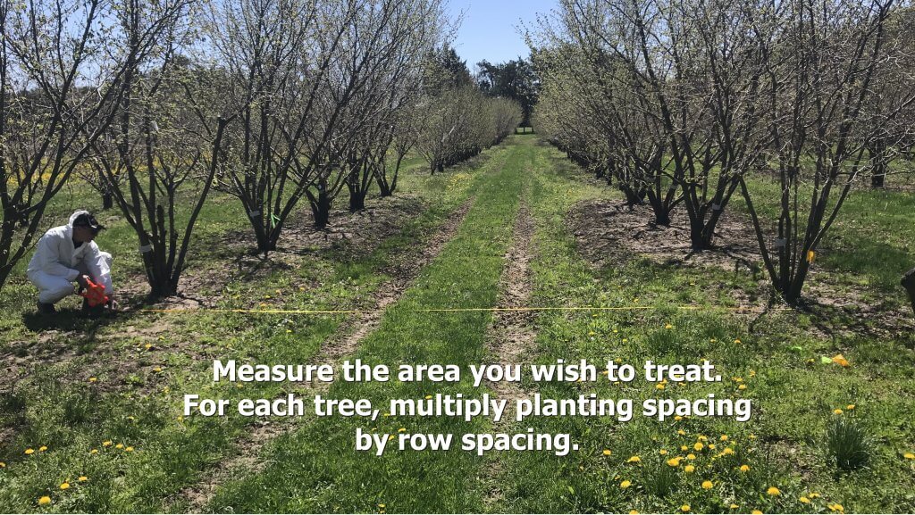
    Use the average planting distance and row spacing in metres. For a panel of grapes, use the centre of each panel as the planting distance.

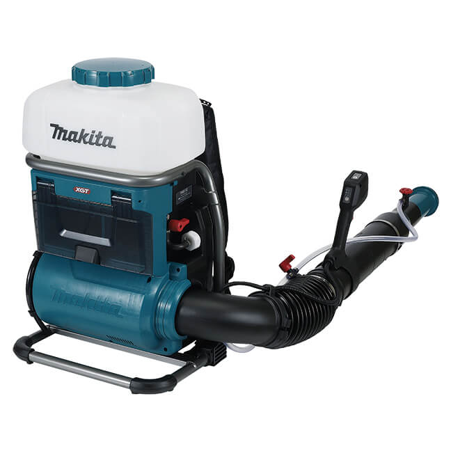
    If you are using a CO2 powered hand wand (preferred over a manual pump) with one or more hydraulic nozzles, then you can calibrate it using the methods in this article. There are battery-powered options from Jacto and Petra Tools, the latter offering a battery powered ULV system as well. Makita also has a battery entry (image below). However, if you are using a backpack mistblower, which better approximates an airblast sprayer compared to a hydraulic hand boom (see this article), it requires a different approach. Plus, you get to look like a Ghostbuster, which is a win in my book.

    PM001GL201 – 40V max XGT Brushless Cordless 15L Backpack Mist Blower (8.0Ah x2 Kit)

    Follow along in the following images as we explore how to calibrate a backpack step by step:

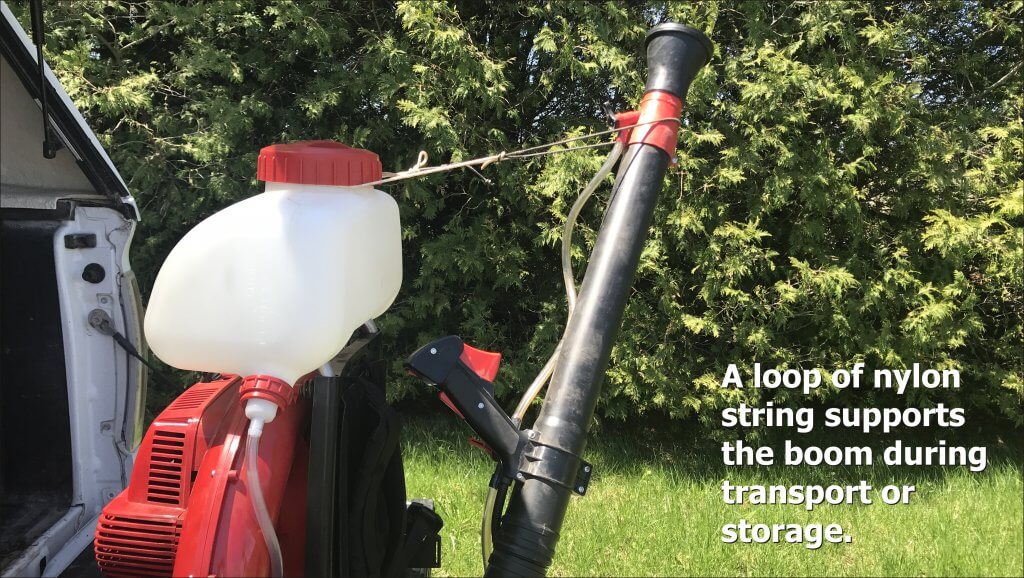
    When transporting a mistblower, use a loop of nylon cord to secure the boom in an upright position.
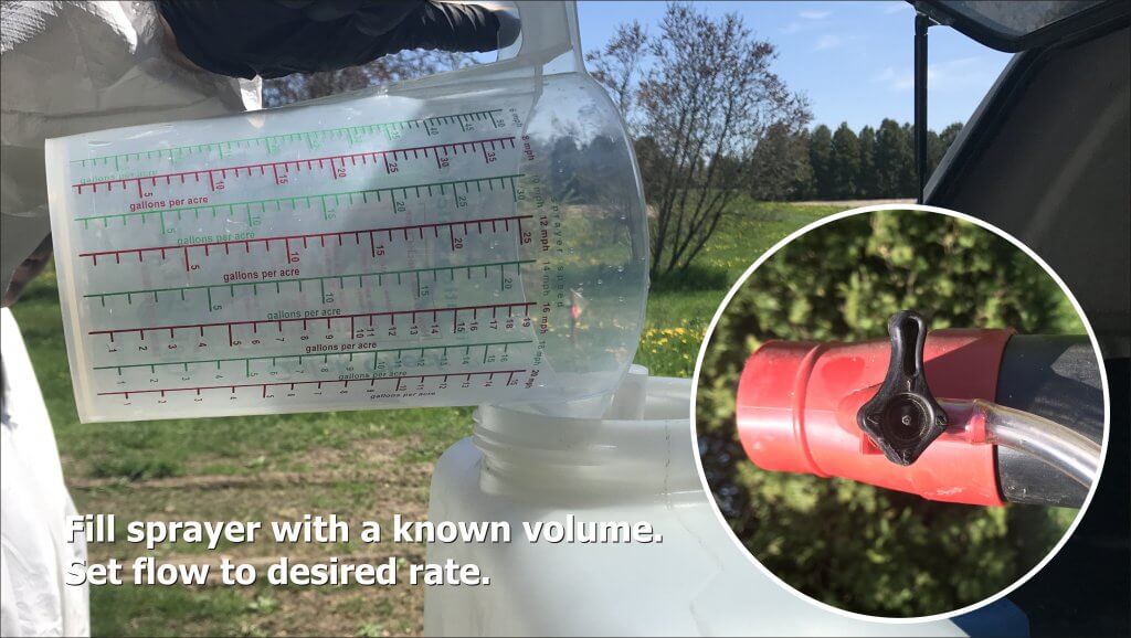
    For calibration, fill the completely empty sprayer with a known volume of water. If the boom is gravity-fed, be sure the feed valve is closed so the water doesn’t run out of the boom.
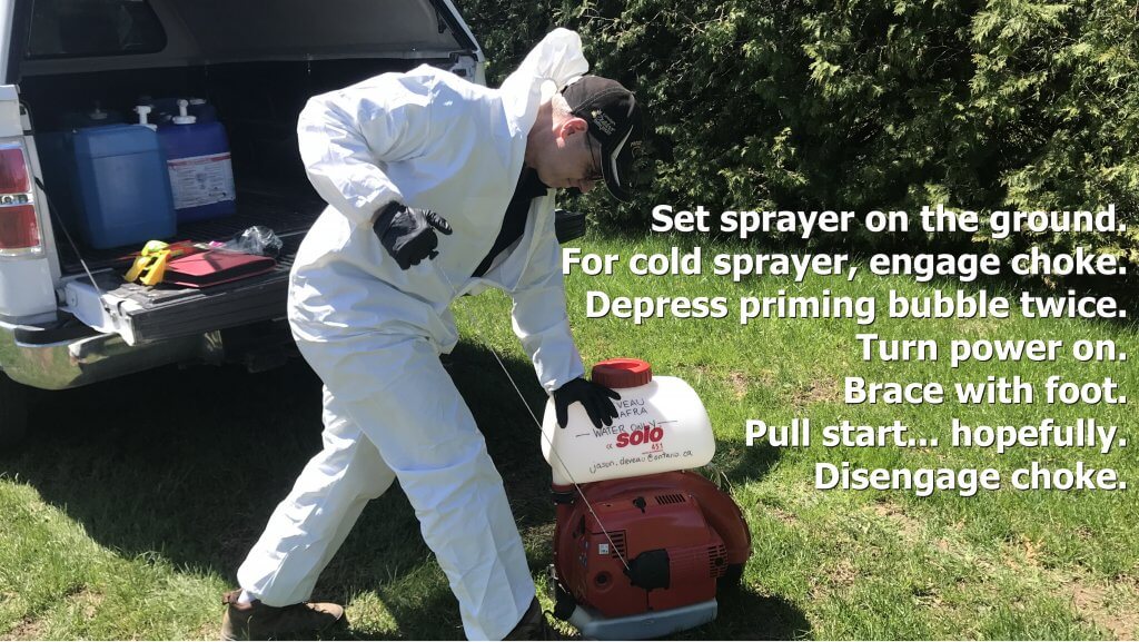
    With the sprayer on the ground, brace it with your foot. Step on the metal frame, not the motor housing or tank. Follow the operating instructions to pull start the motor.
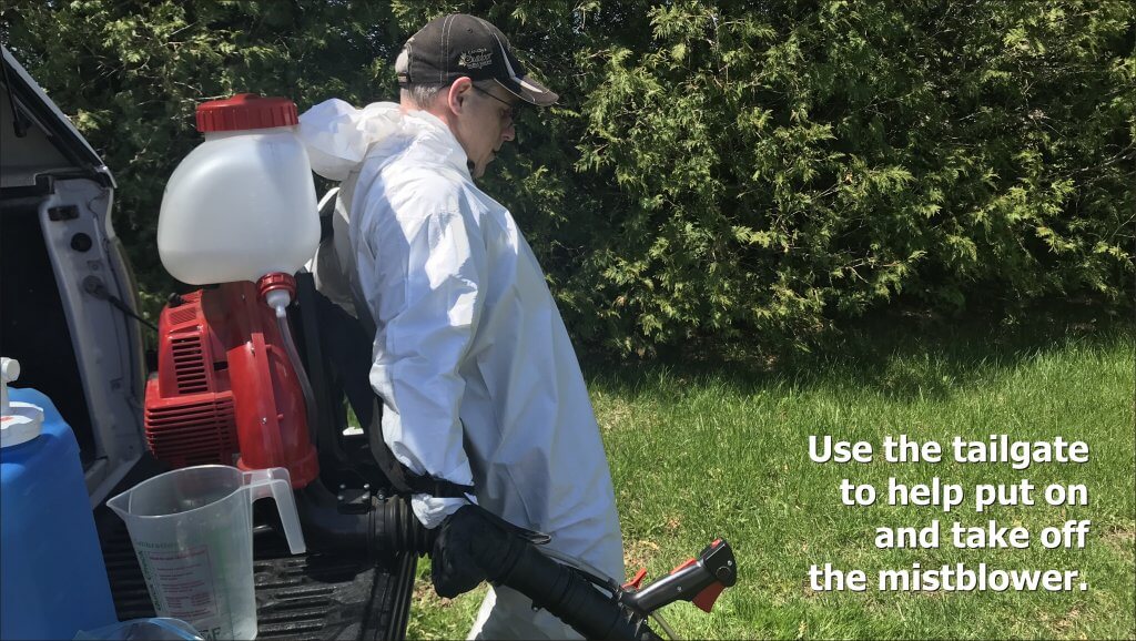
    Being cautious of the hot exhaust, set the sprayer on a tailgate, or other elevated surface to facilitate strapping it on.

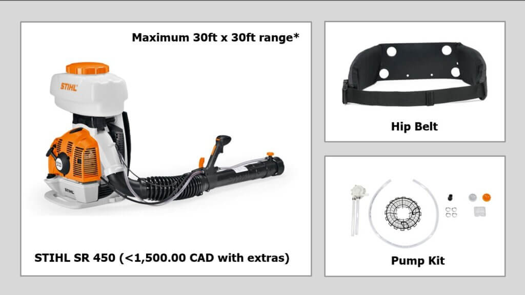
    Be aware that most mistblowers use gravity to feed the spray mix from the tank to the boom. A pressure pump kit is recommended for applications where the spray tube is held upward more than 30 degrees to maintain a consistent discharge rate. A hip belt is also recommended to reduce fatigue. Examples are shown below are for Stihl-brand sprayers. Some may or may not require the pump (e.g. Tomahawk) but they are primarily intended for mosquito control and in that case a consistent rate over a vertical plane may not be as important.

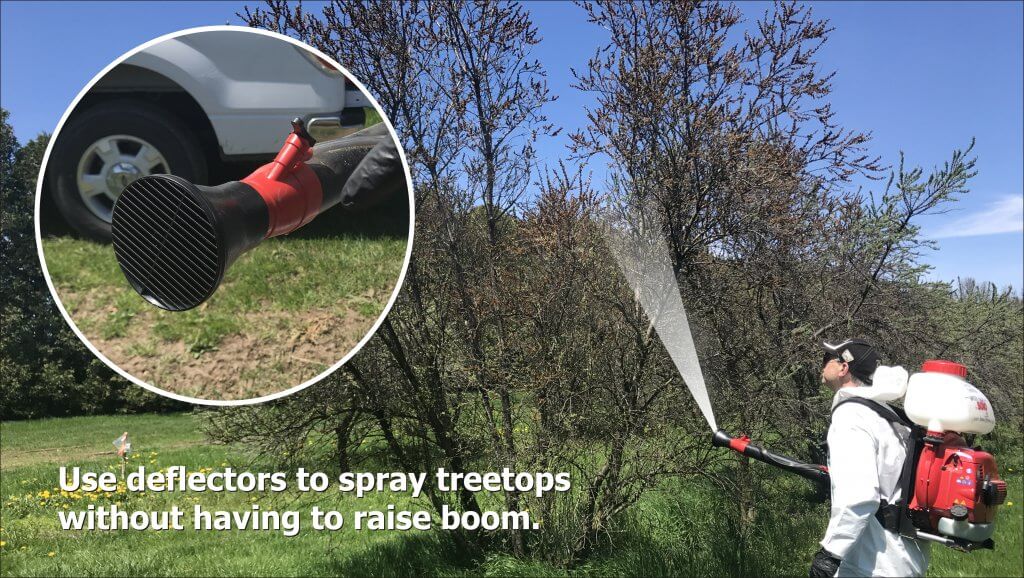
    If your sprayer does not have a pump kit, pointing the boom upward will cause spray to slow or even stop. This greatly diminishes your ability to reach high targets and achieve consistent coverage. In this case, attach the deflector (which comes with the sprayer) before proceeding with the calibration.

    Deflectors angle the spray upwards without having to lift the boom. This is easier on your shoulder and keeps the rate consistent.

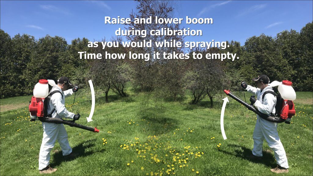
    Set the flow rate to the preferred setting (usually a dial at the end of the boom), and using a stopwatch, time how long it takes to spray the entire volume. Be sure to move the boom exactly as you would when spraying the target, either side-to-side or up-and-down, to capture possible rate changes from the gravity feed. Convert the output to US gal./min.

    When timing output, move the boom as you would when spraying the target.

    Alternately, some people will stand on a bathroom scale with the backpack full. Then get off and spray for a period of time. Then get back on the scale. One millilitre of water weighs one gram, so you can calculate the flow from the weight difference.

    Now you know the area and the emission rate. You should have a target carrier volume in mind (e.g. L/ha). Using the following example, let’s determine how long you need to spray the target:

    A sample calibration.

    In this example, an ideal airblast Carrier Volume [C] for the orchard is 400 L/ha. We want to scale this down to determine the Volume for Treated Area [V]. First, divide [C] by 100 to convert it to 40 mL/m2. Then, because in Canada our nozzles are in US units, we do an ugly conversion: Since 1 mL = 0.000264 US gallons, [C] becomes 0.0106 US gal./m2.

    The Treated Area [A] measures 3.5 m by 2 m = 7 m2.

    The Emission Rate [R] is the rate the plot sprayer sprays. While we prefer using a mistblower, many still use a hand wand with no air assist. In this case let’s suppose we are using a hand wand with two 8002 flat fan nozzles operating at 40 psi. According to our calibration, we confirm it sprays 0.4 US gal./min.

    • [C](US gal./m2) × [A](m2) = [V] (US gal.)
    • 0.0106 US gal./m2 × 7 m2 = 0.074 US gal.

    We know we want to spray the target with 0.074 US gal., and we also know [R] which says our boom emits 0.4 US gal./min. We convert this to seconds by dividing by 60, so [R] = 0.0067 US gal./sec. From this we can calculate how long [T] we must spray the target.

    • [V](US gal.) / [R](US gal./sec.) = [T](seconds).
    • 0.074 US gal. / 0.0067 US gal./sec. = approximately 11.0 seconds.

    So, we know that to spray the target with an equivalent 400 L/ha, we must achieve consistent coverage from all sides by spraying it for a total of 11 seconds. Pro tip: Always mix a little more spray volume than you will need to account for priming.

    This is only one way to calibrate a backpack sprayer for spot spraying. If it’s isn’t quite what you need, check out these resources:

    1. Calibrating a Knapsack Sprayer (www.weedfree.co.uk – 2008)
    2. Don’t Overlook Backpack Sprayers (John Grande, Rutgers)
    3. Hand Sprayer Calibration Steps Worksheet (Bob Wolf, Kansas State University – 2010)
    4. Sprayer Calibration Using the 1/128th Method for Motorized Backpack Mist Sprayer Systems (Jensen Uyeda et al., University of Hawai’i – 2015)
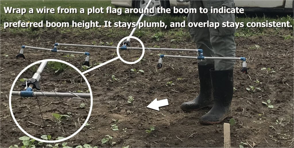
    Pro Tip: To maintain a consistent boom height without a wheel, coil a measured length of wire from a plot marker flag to guide you.

  • Calibrating a Plot Sprayer

    Calibrating a Plot Sprayer

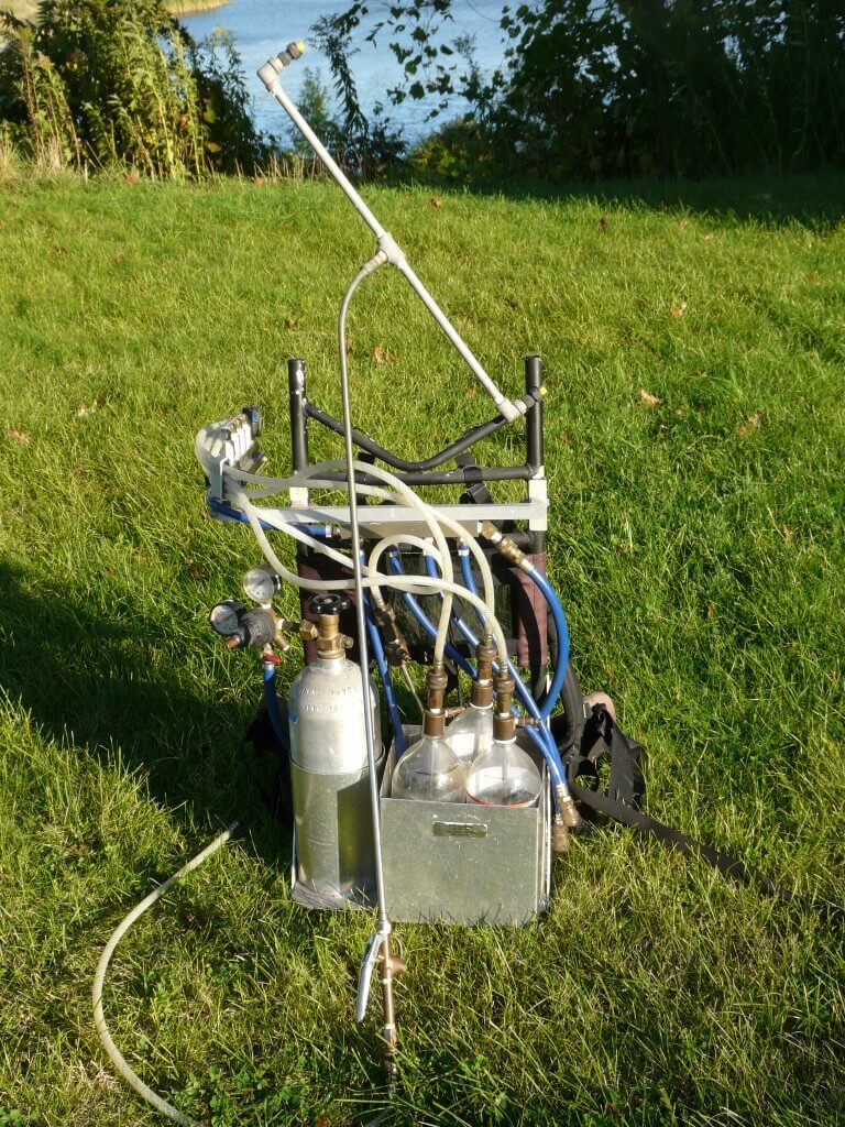
    It’s the rite of passage of many agricultural summer students across the world: applying experimental treatments to field plots using a research sprayer. The results of these experiments may be the basis of new product use registrations, or provide clues into future scientific studies. Needless to say, the application method needs to be bullet proof to ensure the results are reliable. Here are a few guidelines, starting with some tips:

    Pro Tips:

    1. When assembling a hand-held boom, ensure the threads are properly sealed using Teflon tape. More or less tape can be used to create a snug fit at the right part of the thread rotation.

    2. Choose nozzle bodies with diaphragm shutoff valves. These valves stop flow below 10 psi and prevent dripping of the nozzles after shutoff, without pressure drop during operation.

    3. Avoid the use of older style “check-valve strainers”. Although these also prevent drips, they create a pressure loss of about 5 psi which creates uncertainty around the actual spray pressure.

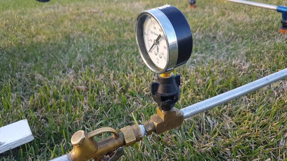
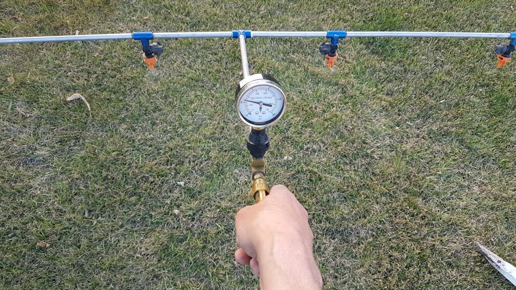
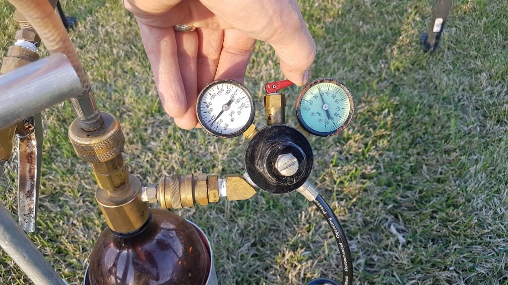
    4. Install a trusted pressure gauge on the handle of the sprayer in clear view for the operator. This provides important information. Don’t believe the gauge on the regulator. Ours, for example, is stuck at 30 psi.

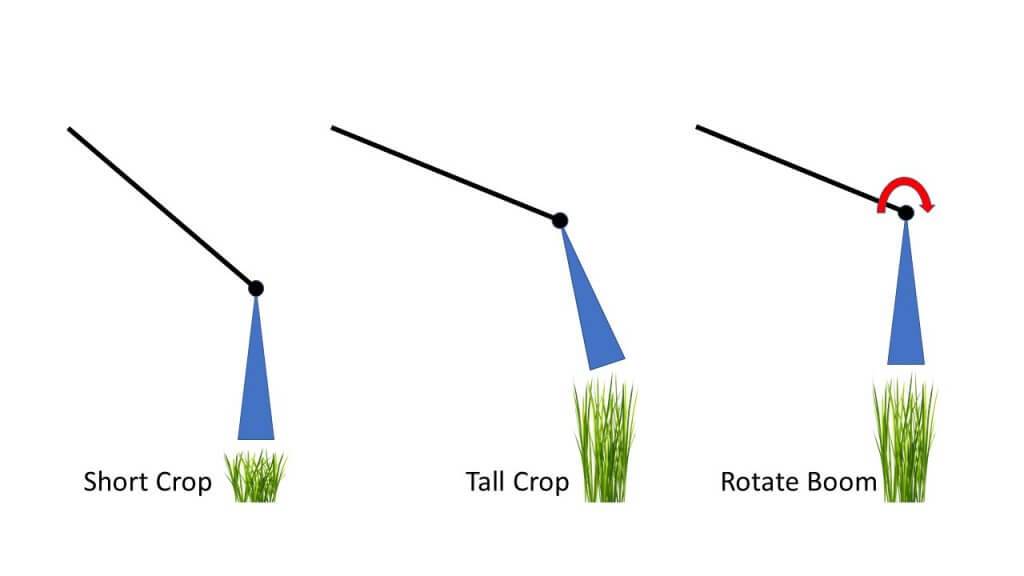
    5. For hand-held booms, rotate the booms so that the nozzles point down, for each application. Different size people or height of crops will change this angle and make accuracy more difficult.
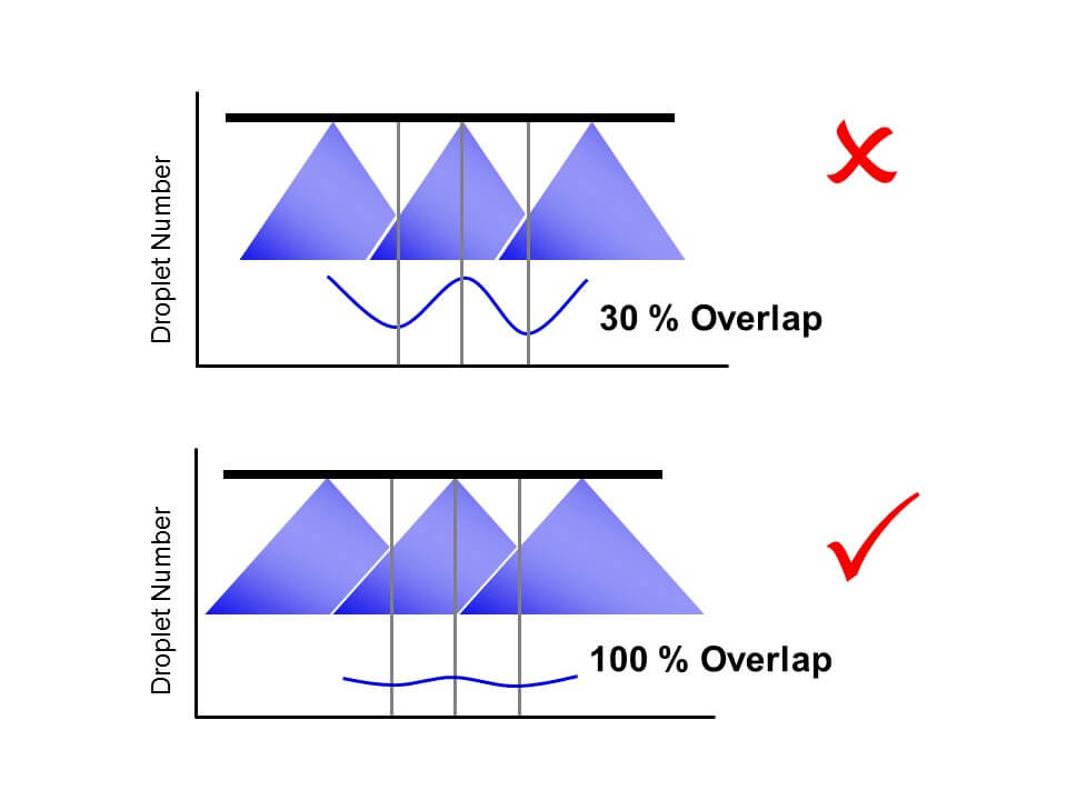
    6. Set the boom height so that you achieve 100% pattern overlap. This means that a nozzle’s pattern width should be twice the boom’s nozzle spacing. Boom height will be close to 50 to 55 cm above target, depending on fan. Too low, and the pattern may cause striping. Your supervisor will see that all year long and think of you.

    7. You can test the spray pattern by applying water to a concrete pad. At the right boom height, the entire boom width should dry at a similar rate.

    8. Install a visual guide for boom height. For example, place a wire flag at the end of the plot, at the correct height. This will provide a handy reference of boom height as your arms get weary. Or hang a wire, zip tie, or chain from a spot that doesn’t interfere with your spray pattern (thanks ACC).

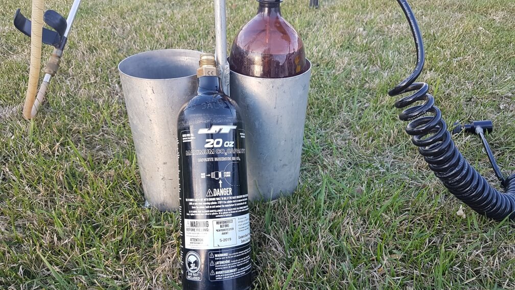
    9. Minimize weight by using smaller bottles of CO2. We use 20 oz paintball bottles, they are much lighter, last long enough, and can be legally refilled with liquid CO2 or topped up with gas from a nurse tank in the field.

    10. Spray out leftover mix in a designated part of the plot area. Do not pour any mix on the ground. Please. Consider a biobed on your research farm.

    11. When completing a treatment, spray the boom completely empty so air comes out of each nozzle. This provides certainty that the next liquid at the nozzles is from the next bottle, be it water or another treatment.

    12. When spraying dose responses of the same product, always start with the lowest dose. Again, spray out in a designated place until the boom produces air, no need to flush.

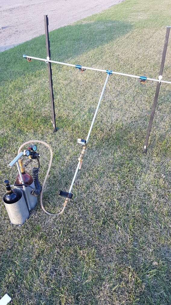
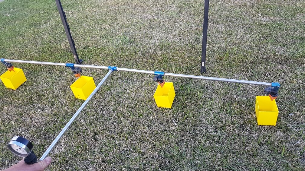
    13. Construct a boom hanger from electric fence posts and coat hangers. Nozzles face down and can be serviced. The boom should never lie on the ground.

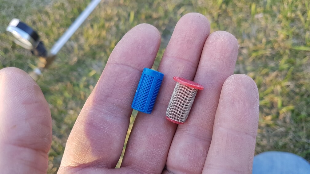
    14. Use nozzle screens to prevent time delays due to plugging. Usually 50 (blue) or 80 (yellow) mesh is sufficient. Any finer mesh may interfere with some dry formulations. Note: Beware old screens – ISO mesh colours have changed. Learn more here.

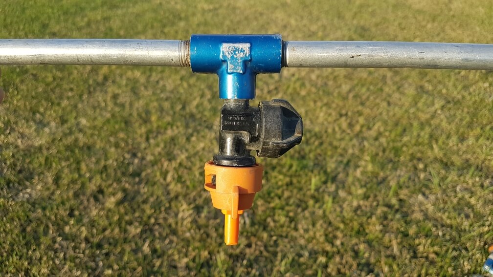
    15. It’s very useful to apply research sprays with low-drift nozzles. Air-induction tips are most effective. These reduce drift, and are also closer to the commercial spray quality used by producers.
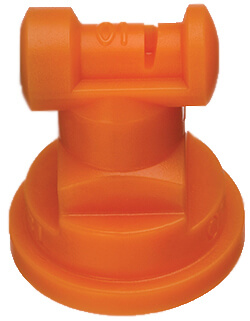
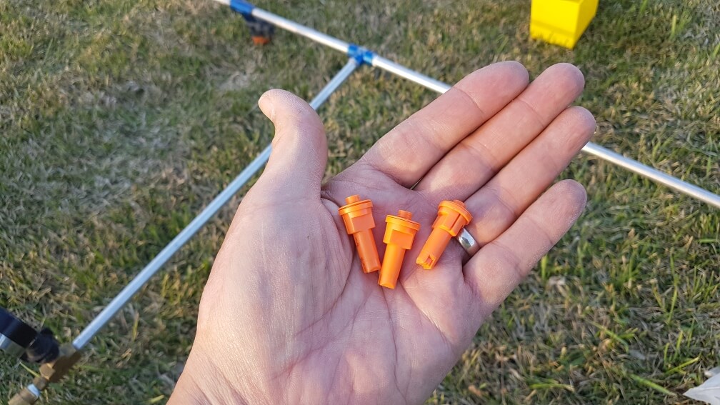
    16. 01 size (orange) air-induced nozzles are available from Albuz (AVI Twin and AVI), Arag (CFA, CFAU, AFC), Billericay (Air Bubble Jet), Greenleaf (AirMix and TurboDrop XL), Lechler (ID3 and IDK). No other major manufacturer produces this small size of tips in air-induction.
    17. 015 size tips (green) and larger are produced by the above, as well as Albuz (CVI Twin and CVI), Hypro (GuardianAIR or ULD) and TeeJet (AIXR, AI, and TTI), within both manufacturers listed in order of increasing coarseness.

    18. Always carry several other nozzles of the same size and type already on the boom. Should a nozzle plug, replace it, don’t clean it. Clean it later.

    19. If a nozzle plugs and there is no extra nozzle, use compressed air to clean it. Compressed air electronics cleaners are available in most electronic stores.

    20. If a plugged nozzle can’t be cleaned, simply place it at the end of the boom and continue. Plot ratings and yields are usually taken from the centre. Remind your supervisor of this.


    21. Always de-pressurize a sprayer before disconnecting any liquid hoses. You can’t rely on check valves. If two people work together, make sure you practice and communicate this with each other.

    Calibration:

    1. Assemble the sprayer and run water through it to ensure it’s free from silt or residue. Repair leaks.

    2. Install nozzles and ensure none are plugged and the pattern looks good.

    3. While spraying water, set pressure to what you intend to spray with. (Note: boom pressure will be lower than regulator (attached to CO2 canister) by a few psi, hence the separate pressure gauge on the boom. Also note that the set pressure will always be higher when the system is at rest.)

    4. Obtain four containers of similar size that can hold about 500 mL, and place on ground at nozzle spacing. Using stopwatch, emit spray directly into all four for a set time, say 30 s.

    5. Expected spray volume at 40 psi: 01 tip, 380 mL/min; 015 tip, 570 mL/min; 02 tip, 760 mL/min. In other words, from a 2 L bottle you’ll not get much more than 30 s spray time from 4 tips.

    6. Measure collected volume from four tips using the same graduated cylinder.

    7. Repeat, for total of three times.

    8. Average three reps for each nozzle and convert to mL/min. Make sure all nozzles are within 5% of the average flow. Replace those that aren’t or place worst offender on outside edge of boom.

    9. Advance to “Calculations”, but be prepared to conduct another calibration

    Now for the fun part.

    Calculations

    There are three options for applying the correct amount. We’ll be using metric in these examples:

    1. Use the average nozzle flow from the calibration (mL/min) and the target application volume (L/ha) to calculate the necessary walking speed (km/h);

      or
    2. Use the flow from the calibration and a set walking speed to arrive at an application volume;

      or
    3. Use a set walking speed and a set application volume to calculate a required calibrated flow.

    Option 1:

    Walking Speed = (60*flow)/(Volume*nozzle spacing)

    If your nozzle flow was 330 mL/min and you wanted to apply 100 L/ha using a sprayer with 50 cm nozzle spacing, your required walking speed is 60*330/100/50 = 3.96 km/h

    Option 2:

    Application Volume = (60*flow)/(Speed*spacing)

    If your nozzle flow was 330 mL/min and you wanted to walk 5 km/h using a sprayer with 50 cm nozzle spacing, your application volume is 60*330/5/50 = 79 L/ha

    Option 3:

    Required flow = (Speed *Volume*spacing)/60

    If your speed is 5 km/h and you wanted to apply 100 L/ha using a sprayer with 50 cm nozzle spacing, your required flow is 5*100*50/60 = 417 mL/min

    If you selected Option 3, you now need to return to your sprayer and find a nozzle, or a pressure, that delivers an average of 417 mL/min. You can use math to get into the ballpark with the nozzle you already have:

    New Pressure = (required flow/calibrated flow)2*calibrated pressure

    If your required flow is 417 mL/min and the calibrated flow is 330 mL/min, and you calibrated at 30 psi, then you should be close to your required flow at (417/330)2*30 = 48 psi

    Now, return to your sprayer, set the pressure to 48 psi, and confirm this estimate.

    We use Option 3 when comparing nozzles of the same size but from different manufacturers. It’s not uncommon for these to have slightly different outputs. Rather than adjusting our walking speed slightly, which is very difficult to do accurately, we change pressure slightly so all nozzles produce the same flow. This is also useful when comparing water volumes by switching to a larger nozzle.

    Travel Speed:

    The last step is to confirm travel speed. Say you want to walk at 5 km/h. The best way to calibrate walking speed is to measure a known distance (m) in the field you’ll spray. Wearing the gear and carrying the sprayer you will use to spray, walk this distance. Use a wire flag to mark the start and end points; when the boom hits the flags, start and stop the timer. Repeat until comfortable.

    Time needed to walk distance:

    Time (s) = Distance *3.6/required speed

    Say your walking distance is 10 m, and you need to walk 5 km/h.

    10*3.6/5 = 7.2 s

    A simple spreadsheet that can be used for the calculations can be found here.

    Congratulations! You’re done. Happy spraying! Remember to not worry too much about a 5% deviation from your expected application. That’s definitely an acceptable error, as long as you don’t allow too many of those to add up.

    Low Volume Research (Aerial)

    Some product uses are by air, and the label volumes for those are often 30 to 50 L/ha. Registrants need to provide efficacy data at those volumes. Ground application can be accepted as a surrogate for aerial as long as the volumes are correct.

    Since the spray nozzles aren’t typically available below the 01 (orange) size and if they are, they usually plug so easily and make such a fine spray that they’re frustrating to use. The alternative, to travel faster, is also problematic on research plots.

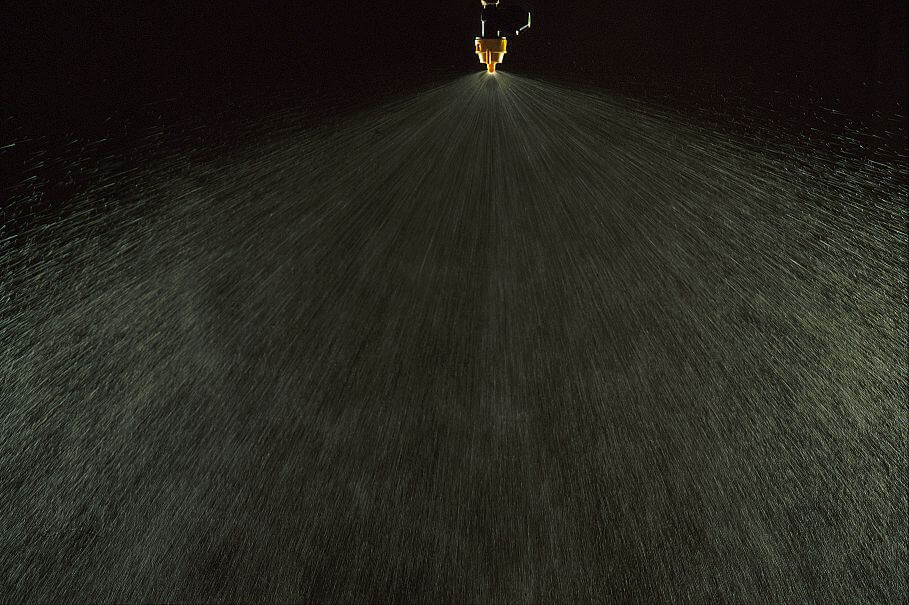
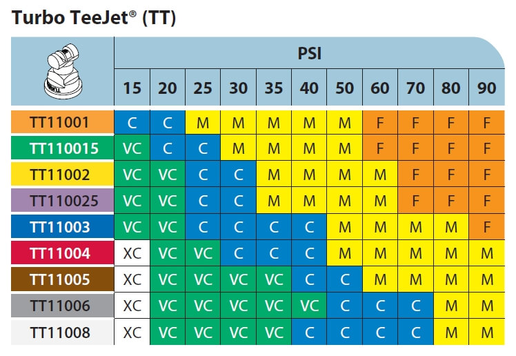
    We recommend that Turbo TeeJet nozzles be used for this purpose. They produce such a wide fan angle that a 100 cm spacing is justifiable. Simply cap off every second nozzle body. Booms need to be elevated to ensure overlap, for uniformity. The value of the small nozzles and wider spacings is the low total application volume that is now possible.

    The TT tips can also be used at fairly low spray pressures (say 20 psi) further reducing their output.

    Spray Quality of TeeJet Turbo TeeJet (ASABE S572.1). This tip is available in smaller sizes and, due to its wide fan angle, can be used at 40″ (100 cm) spacing, therefoe applying low water volumes.

    /

  • How to Calibrate a Drone – Swath Width Calculation

    How to Calibrate a Drone – Swath Width Calculation

    Calibration is a fundamental step in any spray application. To apply the correct product rate, we need to know how much liquid per unit land area is deposited under the sprayer.

    To conduct the calculations, either manually or through the drone software, we need to know the width of the spray swath. This task requires the operation of the sprayer under typical conditions, some kind of sampler capture the spray deposit, and a means of quantifying that deposit so the spray pattern becomes apparent. Here’s how we do it:

    1. Confirm the accuracy of the flow meter

    Drones don’t typically report the spray pressure of the spray mix. Instead, they report the flow rate using a built-in flow meter. The drone maintains the desired application rate by using the flow rate to adjust pump speed and engage nozzles over a range of travel speeds. Because everything depends on the flow meter, its accuracy needs to be verified.

    • Fill the spray tank with clean water and flush all the lines.
    • Install nozzles required for task, ensuring all nozzles are identical and in good working order.
    Nozzles installed on DJI T20 drone.
    • Select the nozzle size you installed on the spray monitor.
    • Purge the air from the system.
    • Activate the spray and wait for the flow rate to stabilize on the spray monitor. This may take a few moments.
    • With the nozzles flowing, place collectors under each nozzle and collect the spray liquid for a fixed time, say one minute.
    Capturing spray during flow meter calibration.
    • Ensure the collector catches all the spray. Buckets often create turbulence. Rotary atomizers make this more difficult.
    • When the time elapses, remove the collectors and then shut off the spray.
    • Unless the shutoff is very fast and positive, leaving the collectors in place during shutoff can introduce error as the flow diminishes.
    • Confirm that the volume collected from each nozzle was identical, and that the flow rate reported by the drone flow meter is accurate.
    • Repeat to ensure consistency.
    Use of a Spot-On digital calibrating cup ensures that all spray is captured and it also reports the volume instantly.

    2. Measure the swath width

    Spray swath width is variable. For a measurement to be relevant we must evaluate spray deposition under environmental conditions that are similar to the planned spray operation, as well as use the same operational settings such as altitude, travel speed, nozzle choice, and application volume.

    Spray samplers are positioned along the ground, perpendicular to the flight path. We use water-sensitive paper (WSP) because it’s readily available, fast and easy to use, and the deposits can be analyzed visually or using simple apps that calculate coverage. We create a sampling line of WSP positioned a 1 m intervals (or maybe 0.5 m for narrow swaths). The samplers should extend to twice the expected swath width to account for any swath displacement from sidewinds.

    • Choose a day with light, consistent winds.
    • Find an open space free of obstruction in the direction of the prevailing wind.
    • Install a weather station to document conditions during flight.
    A Kestrel 3550AG or 5550AG wind meter can record weather data and download to a phone via Bluetooth.
    • Mark an approximately 200 m long flight line into the prevailing wind direction by placing wire flags every 50 m.
    • At the 150 m mark, use wire flags to centre a sampler line perpendicular to the flight path. Sampler line length should be about twice the expected swath width.
    Swath sampling line
    • Wooden blocks with paper clips can be used to secure WSP at regular intervals along the sampler line.
    Wooden blocks attached to a 4″ tow strap allows for easy setup and movement of sampling line.
    • Fill the drone 1/2 full.
    • Manually fly the drone along the entire flight line. The spray pressure, flow rate and altitude of the drone should be stable before it reaches the sampler line. This may take 25 meters or more depending on drone model, flight speed and drone weight.
    • Fly 50 m past the sampling line without any drone maneuvering to avoid affecting the deposit.
    • Land the drone and walk along the sampler line.
    • Note the deposits in the central region. Walk along line as the deposits taper off, looking for deposits that are approximately 50% of the average central deposits.
    Water-sensitive paper following a drone application.
    • Estimate the distance between these deposits on both edges of the swath. This is the estimated swath width that can be entered for the second flight.
    • Replace the WSP with a fresh set, refill the drone to 1/2 full, and repeat the flight two more times.

    Other methods perform a more advanced assessment by analyzing the entire swath, and not just intervals. These methods use dyes and dedicated hardware to quantify the deposits along strings or paper samplers.

    The Swath Gobbler documents swaths at high resolution using lengths of 3″ bonded receipt paper, food grade dye, and a digital scanner.
    The Application Insight LLC Swath Gobbler scanner in action.

    3. Analyze the Pattern

    The nearest approximation for drone swathing is that of a manned aircraft. The spray pattern of an aircraft is tapered, meaning the highest deposition is near the centre of the swath, and the edges of the swath fade to zero deposit. In order to achieve consistent coverage, we need the edges of the spray swath to overlap so the cumulative coverage at the edges is closer to that in the centre. Too little overlap leaves gaps and too much overlap results in excessive deposit.

    Insufficient overlap creates gaps in coverage
    Excessive overlap results in over-dosing and waste
    Correct overlap is necessary for efficient and effective application.

    Deposits from drones can be highly variable. The challenge is to find an overlap distance that minimizes this variability, minimizes both over- and under-application, and maximizes swath width. Download a copy of our Excel spreadsheet to help you with this process.

    The first step is to estimate a reasonable average deposit, called “Threshold”. Graph the deposits from each sampler, and estimate a point on the Y axis (Relative Deposition) that represents the average maximum deposit. This could be the maximum value of the plateau, or a midpoint between the maximum and a nearby dip. This is the Threshold. We then take 50% of this estimated average deposit, and find the two distances on the X axis (Sampler Locations) that intersect the curve at these points. The distance between these two points is our first estimate of the swath width. If two adjacent swaths are spaced so the edge of one overlaps 50% with the next, the overall cumulative deposit should be relatively even.

    The coverage information from each sampler location is graphed to create a deposit pattern.

    We can alter the amount of overlap to improve the apparent uniformity, but be cautious. For example, even though we can often improve the uniformity by narrowing the swath width, this can add deposit to the area under the drone and raise the overall deposit amount. Plus, the narrower swath also lowers the productivity of the drone. Use the Excel model to establish a swath width that has the lowest variability (Coefficient of Variability or CV) AND results in a balance between over- and under-dosing.

    The amount of overlap is adjusted to minimize variability (CV) and both equalize and minimize over- and under-dosing.

    4. Recognize the factors that influence swath width

    Operational use case affects swath width

    Swath width is affected by altitude, speed, water volume and spray quality. Generally, higher altitudes, lower volumes, and finer sprays will result in a wider swath. Unfortunately, the same configuration also results in greater drift. It is recommended that swath widths be determined for each spray volume and nozzle arrangement that will be used.

    Drones will be applying low water volumes and this requires a critical assessment of coverage to ensure the deposit density is sufficient to achieve the desired result. A low volume will require a finer spray for minimum coverage to be realized. Coarser sprays that reduce drift and evaporation will need higher water volumes and result in narrower swaths. Significant time may need to be invested to understand the effects of operational settings and environmental conditions on spray deposit uniformity and swath width.

    Effective Swath Width and the Agronomic Use Case

    The relatively sparse coverage at the extremes of the measured swath width may be insufficient to elicit the desired biological result. The Effective Swath Width (ESW) represents the segment of the total swath width that results in pesticide efficacy. In some use cases, the two widths can be similar, but typically the ESW is only a fraction.

    The difference is influenced by the “Agronomic Use Case” which includes factors such as:

    • Spray mix rheology (i.e. the interaction of spray mix viscosity and atomizer design on droplet size)
    • Minimum effective dose: This is a complex relationship between coverage, spray mix concentration and pesticide mode-of-action that results in an effective result while minimizing the environmental impact.
    • Target location (e.g. a pest within a dense canopy or a weed on relatively bare ground)

    Taken collectively, research has shown a 20-30% reduction in ESW for corn, wheat and soybean fungicide applications compared to swaths measured on open ground. Conversely, herbicides sprayed on bare earth or sparse vegetation can produce an efficacious response 20% wider than the measured swath width. The impact of agronomic use case on ESW must be considered during mission planning.

    Additional pointers

    Here are a few tips and tricks to help you be successful when calibrating your drone.

    • Drone patterns will have deposit peaks and valleys in the central region. Repeated runs are needed to confirm that these are real and persistent. If so, then adjustments in flying height, spray quality, or water volume may be needed to eliminate them.
    • The absence of pressure gauges on drones can be corrected by installing an analog gauge in-line with one of the spray nozzles. If may be necessary to mount an auxiliary camera on the drone to record this gauge. We have observed strong fluctuations in spray pressure, particularly on starting a spray swath, that were not reflected in the reported flow rate.
    A pressure gauge can be plumbed into a drone without affecting flight behaviour. A camera is trained on it to read pressure during a flight.
    • Many drones have the option of recording the flight screen during a mission. This will provide a record of the performance of the drone, and can be valuable should performance problems arise.
    • Although swath width calibration is done by flying into a headwind, the actual spray application should be done with a side wind. Start at the downwind edge of the field and turn into the wind. The drone is symmetrical and the tapered spray patterns should equalize the deposits. Alternately, flying into a headwind and returning with a tailwind can alter the aerodynamics of the spray deposition process, alternating between a wider and more narrow swath width, respectively.

    Drone spraying will walk a razor’s edge of sorts – there is little room for error when using scant water and fine droplets. Getting the basics right has never been more important.

  • Mode of Action and Spray Quality

    Mode of Action and Spray Quality

    The decision on which application method is best for herbicides boils down to two main factors: (a) target type and (b) mode of action. In general, it’s easier for sprays to stick to broadleaf plants on account of their comparatively larger leaf size and better wettability compared to grassy plants. There are exceptions, of course – at the cotyledon stage, broadleaf plants can be very small and a finer spray with tighter droplet spacing may be needed. Water sensitive paper is a very useful tool to make that assessment. Imagine if a tiny cotyledon could fit between deposits – that could be a miss!

    Some weeds are also more difficult to wet, and those may also need a finer spray or a better surfactant for proper leaf contact. An easy test is to apply plain water to the leaf with a spray bottle. If the water beads off or the droplets remain perched on top in discrete spheres, the surface is considered hard to wet. Most grassy weeds are hard to wet, while most broadleaf weeds are easy to wet.

    Grassy weeds are an especially difficult target because they have smaller, more vertically oriented leaves, and almost without exception are more difficult to wet than broadleaf species. All these factors call for finer sprays for effective targeting and spray retention.

    Broadleaf weeds usually have more horizontally oriented leaves which also happen to be larger. As a result, they can intercept larger droplets quite efficiently.

    There are about thirty mode of action (MOA) groups among the herbicides with about ten accounting for the majority in Canadian prairie agriculture. It’s probably an over-simplification to categorize them into just two groups – systemic and contact.  But that grouping goes a long way to making an application decision.

    Contact products (MOA Group 5, 6, 10, 14, 22, 27) must form a deposit that provides good coverage. Good coverage is an ambiguous term that basically means that droplets need to be closely spaced and cover a significant proportion of the surface area because their physiological effects occur under the droplet, and don’t spread far from there. One way to generate more droplets is to reduce droplet diameter, another is to add more water. A reasonable combination of both is ideal because simply making droplets smaller creates issues with evaporation and drift.

    Systemic products (MOA Group 1, 2, 4, 9) will translocate within the plant to their site of action after uptake. As a result, coverage is less important as long as sufficient dose is presented to the plant. In practice, this means coarser sprays and/or less water may be acceptable.

    When two factors are combined, either in a tank mix or a weed spectrum, the more limiting factor rules. Application of a tank mix or product that is active on both broadleaf and grass plants will be governed by the limitation placed on grass targets. A tank mix comprised of both systemic and contact products is governed by the limitations placed on contact products.

    A factor we should also consider is soil activity and the presence of residue. Studies have shown that soil-active products are relatively insensitive to droplet size. But if they have to travel through a layer of trash to get to the soil surface, more application volume is the best tool.

    Below are some recommended spray qualities and water volumes for use in Canada. The spray qualities listed in the table can be matched to a specific nozzle by referring to nozzle manufacturer catalogues, websites, or apps. Note that Wilger also offers traditional VMD measurements on their site, allowing users to be a bit more specific if necessary.

    Click here to download PDF

  • Recirculating Boom Options

    Recirculating Boom Options

    If you read this site, you know we’re fans of recirculating booms. We love them for three reasons:

    1. They save money and waste by recovering spray back to the tank during priming and rinsing
    2. They make boom cleaning easier by eliminating boom-ends
    3. Most require individual nozzle shutoff, which makes for better sectional control

    If you’re new to the concept of recirculating booms, read more here.

    Until recently, these booms were only available on sprayers imported from outside North America (Horsch, Amazone, Agrifac to mention three), or via France’s Pommier booms that have been available as retrofits for many years. In 2018, Agco introduced their Liquid Logic system on the Rogator line, becoming the first North American manufacturer to offer a recirculating boom at the factory. Pattison Liquid also offers Recirculating booms as standard equipment on their Connect Sniper pull-type sprayer.

    In the meantime, three boom retrofit kits and one sectional conversion kit have become available.

    Arag Australia‘s BRS (Boom Recirculation System)

    The first was developed by Arag Australia, and is available there via Nozzles Online, and in Canada through Nozzle Ninja. Designed for John Deere R-Series and Case Patriot sprayers, the kit uses the existing line that feeds liquid to the outermost section and simply extend that line to the end where it enters the boom via two installed elbows. The liquid returns to the centre via the installed boom sections which are connected together by removing the boom end cap (or “aspirator” for John Deere) and replacing the gap with a section of hose. Back at the centre rack, the liquid from both booms meet in the middle. At this point, a three-way valve gives the choice to return the spray to the tank, or to receive pressure from the pump. There is also a manual valve that allows the return to be dumped for safe disposal.

    Arag Boom Recirculation System (Spray Mode)
    Arag Boom Recirculation System (Recirculation Mode)

    The system does not tie into the sprayer’s electronics. instead, it adds a switch in the cab that the operator uses to switch from spray mode to recirculation mode. The switch is not activated at the end of each swath, but instead to prime or flush the boom.

    A switch is added so the user chooses recirculation or spray mode. The boom would recirculate to prime or flush, and remain in spray mode during the spray operation.

    Raven

    Raven offers a recirculation kit for 3000, 4000, and 5000 series Case Patriot sprayers with Aim Command HD and an ISOBUS terminal. The approach is slightly different, as they retain the pressure feed through individual sections but also tie the sections together so the spray is returned to the tank. By including a shutoff valve between each section, the system retains the option to use conventional sectional control for high flow situations, or to isolate a section should a leak occur. The system can be configured and controlled from the sprayer monitor, either a Viper 4+, CR7, or CR12.

    Raven Boom Recircualtion System schematic (from Raven manual). Note the retention of section valves and the addition of manual valves between sections.

    John Deere

    On March 2, 2021, John Deere announced a 2022 factory option called Pressure Recirculation and Product Reclaim. The system keeps several existing sections and adds two steel lines the flull length of each boom wing. One is for supply, the other return. As these lines approach a section, the supply is fed to one end of the section and the return is connected to the other end. On a 120′ boom, there are five recirculating sections, two on each wing and the centre.

    This approach adds one more line than the other designs, and this line will hold materials that ultimately need to be cleaned, flushed, and possibly dumped or sprayed out for cleanout. A possible reason for the extra line is the ability to deliver 220 gpm to the boom, an advertised feature of John Deere high flow booms that may come in handy for topdressing liquid fertilizer. These levels of volume are not needed for pesticides.

    John Deere Boom Recirculation and Reclaim. Top two lines are supply and return and extend the length of each boom wing. These connect to the existing sections on each wing, creating several smaller recirculating sections.

    Latitude Ag

    This Wisconsin company has developed an innovative product that converts any existing plumbed section that contains boom ends into a recirculating section. It does this by incorporating a boom recirculation valve” (the “Merlin IC System“) into the original section feed line. Boom end caps are removed and replaced with sweeps and hoses that return flow to these boom valves. The flow from the boom ends is incorporated back into the sectional feed thanks to a venturi design in the recirculation valve.

    A prototype of the Merlin IC System valve made by Latitude Ag

    Advantages of this design include simplicity. No moving parts are required, the valve simply recirculates the flow from the boom ends automatically whenever that section operates. Existing sectional control, whether it’s by plumbed section or individual nozzle bodies, is unaffected. Flushing the boom with water is done with normal spraying. It takes some extra time to incorporate and dilute the contents of the boom end return lines but results in a clean boom and no section end residue. We’ve seen the results of testing and agree that it works.

    This product does not allow boom priming without spraying. However, a key advantage is that it can be used with direct injection since no product is returned to the tank. Latitude Ag says it will provide the necessary flow sensor and software to make this possible. As of 2025, this system may no longer be commercially available.

    Precision Planting ReClaim

    ReClaim is capable of operating on a sprayer with or without individual nozzle shutoff. For conventional nozzle bodies containing the original spring-loaded diaphragm check valves, the concept is to drop the liquid pressure below the cracking point of the check valves so flow continues through the sections and back to the tank without engaging the nozzles.

    Recirculation fittings are added to the end of each boom section. These feed into 3/4″ lines are installed on section ends, which in turn feed increasing diameter collector lines that eventually return all flow to the tank. Flow reaches the sections as before. When recirculation is turned on, flow exits the boom section through the new fittings and returns through 3/4″ lines to the centre of each section, where it enters 1” lines that take the flow to the center of each boom wing. There the flow in the 1” lines is combined moves to the center of the sprayer on 1.5” lines where it meets the flow from the other wing.  From there, the flow returns to the tank through an electronic ball valve and 2” line. This system ensures no back-pressure and balanced flow from each section.

    For some sprayer rate control systems such as John Deere, the pump won’t operate below about 20 psi despite operator settings. This means the priming or flushing procedure would trigger nozzles to spray if the bodies were fitted with spring-loaded diaphragm check valves. A pressure reduction kit (a second restrictor valve) is required to reduce the pressure sufficiently for ReClaim to work in these instances. More here.

    ReClaim operates independently of any electronic control systems, relying on a toggle switch to initiate recirculation. When flow back to the tank is detected, a light indicates that recirculation is working, and the operator waits approximately 60 sections for a 120’ boom to circulate all volume back to the tank. Download the operator’s guide, here.

    This system requires a lot of additional lines. A 120’ boom would require 120’ of additional 1” line and 60’ of 1.5” line. The manufacturer states that ReClaim adds about 14 gallons of volume that would need to be displaced back to the tank, adding to the standing volume. This volume can be circulated using solution from the main solution tank, or displaced back to the tank using flow from an existing clean water tank, or displaced using compressed air via an optional pneumatic port. It is not clear how spray mix in the ReClaim system can be removed from lines without returning it to the tank and draining it from there. Users should consider the additional surface area and volume that will have to be addressed during cleanout.

    Do It Yourself

    If none of the available options work for your sprayer, consider building your own system. Sprayer plumbing parts are available from the major manufacturers Banjo, Hypro, TeeJet, and Wilger. Wilger, in particular, has developed a nice suite of parts well suited to recirculating booms, including flanged sweeps and thin gauge steel booms, punched for nozzle bodies or unpunched to move product. See their support for DIY projects on this dedicated page: Wilger Retrofit.

    Take Home

    All these recirculation options improve the status quo of plumbed boom sections with boom ends. They should be considered essential equipment on sprayers.