Category: Tables & Apps

Calculators, tables and applications

  • How to Use a Nozzle Flow Chart, With a Surprising Twist

    How to Use a Nozzle Flow Chart, With a Surprising Twist

    Undoubtedly, the number one question we get from operators is: “Which nozzle should I get”? Luckily there’s no simple answer, or we wouldn’t have jobs! The reason it’s not simple is because selecting the “right” nozzle for a sprayer is a process. It can be broken down into two steps:

    • identifying the right flow rate (aka nozzle size)
    • choosing a specific nozzle model (i.e. brand, spray pattern type, spray quality, etc.)

    It’s a big question, so let’s tackle just the first bullet: identifying the right flow rate.

    All sprayer nozzles come in standardized (ISO) sizes, and these sizes are usually identified by numbers stamped on the nozzle as well as the colour of the nozzle itself. The nozzle’s key characteristics (i.e. the fan angle and nominal flow rate), are identified in a format that looks like some version of this (Fig. 1):

    2013_Nozzle_Nomenclature
    Fig. 1: Typical information printed on modern nozzles.

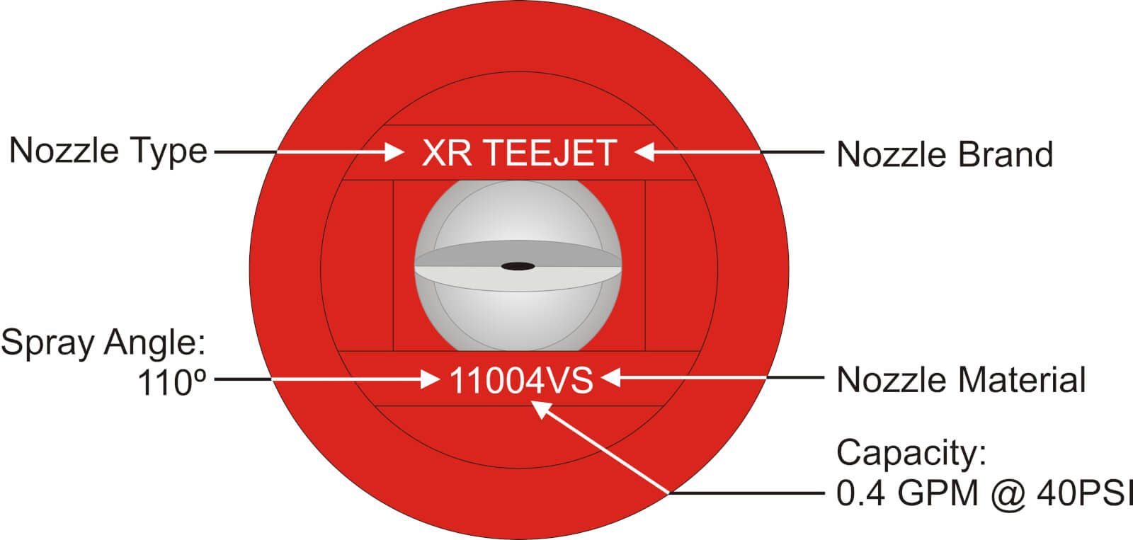
    The 110 refers to the fan angle (110°) and the 04 refers to the flow rate. 04 means 0.4 US gallons of water per minute (gpm) at 40 psi. Each nozzle brand has a slightly different convention, but no matter how the information is presented it ought to be on the nozzle somewhere.

    Nozzle colour has an ISO standard across fan-style nozzles, and we have this table to match the nozzle colour to the flow rate:

    Fig 3: ISO nozzle colours and flow rates

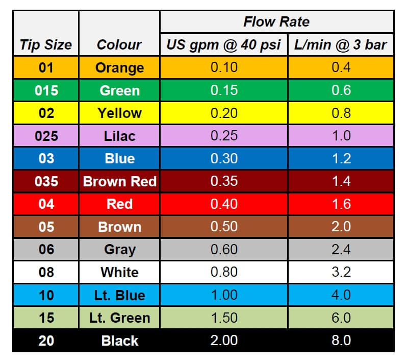
    You’ll note that the nozzle we pictured earlier was “flame red”, matching the 0.4 gpm on the table. So how do we use the table to pick the right size nozzle?

    Application rate (i.e. gallons per acre or L/ha) is a function of travel speed, nozzle spacing along the boom, and nozzle flow rate. Traditionally, this has been expressed as the following formula in US units:

    US Calibration Formula

    This formula is famously represented in nozzle charts found in all sprayer catalogues (Fig 4). Along the left side are nozzle sizes and pressures. Along the top is sprayer speed. The body of the table contains application volume. Pick your speed, and look for your application volume in the columns. If you want to apply five gpa, you need to look for the number 5 (or as close as you can get to it), among these numbers.

    Hypro Calibration Chart
    Fig 4: Typical nozzle flow rate chart, with speed at top and volumes in body. Ugh.

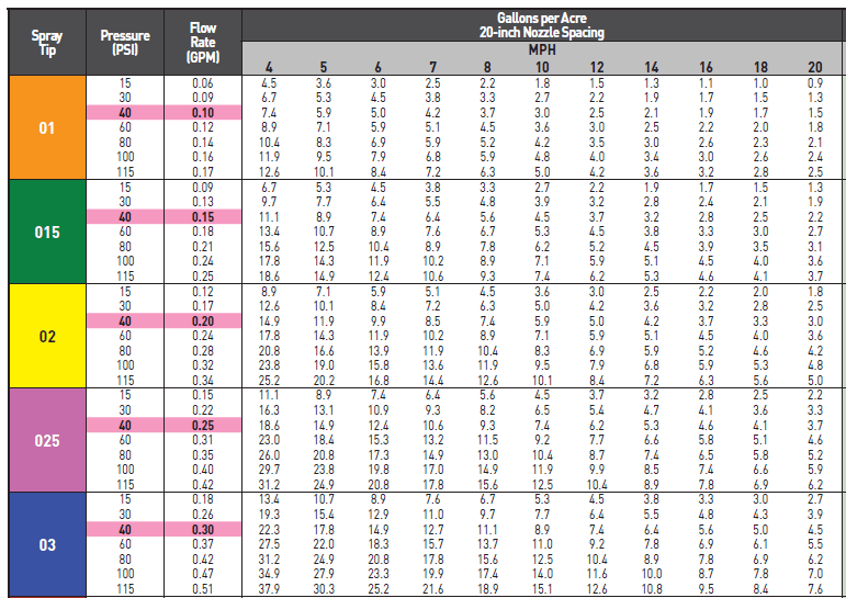
    The format of the chart can be confusing because it doesn’t follow a modern sprayer operator’s priorities. Usually, an operator decides on an application volume first, and this decision is not very flexible. Travel speed, decided second, has more flexibility.

    We’ve therefore re-worked the table to make more sense (Fig. 5). Along the top are common water volumes. The body of the table are travel speeds. Pick a water volume at the top and follow the column underneath this value to find a speed range you’re comfortable with. To the left, the nozzle size and corresponding operating pressures are now visible.

    Fig. 5: Nozzle flow rate chart with volumes at top makes it user friendly.

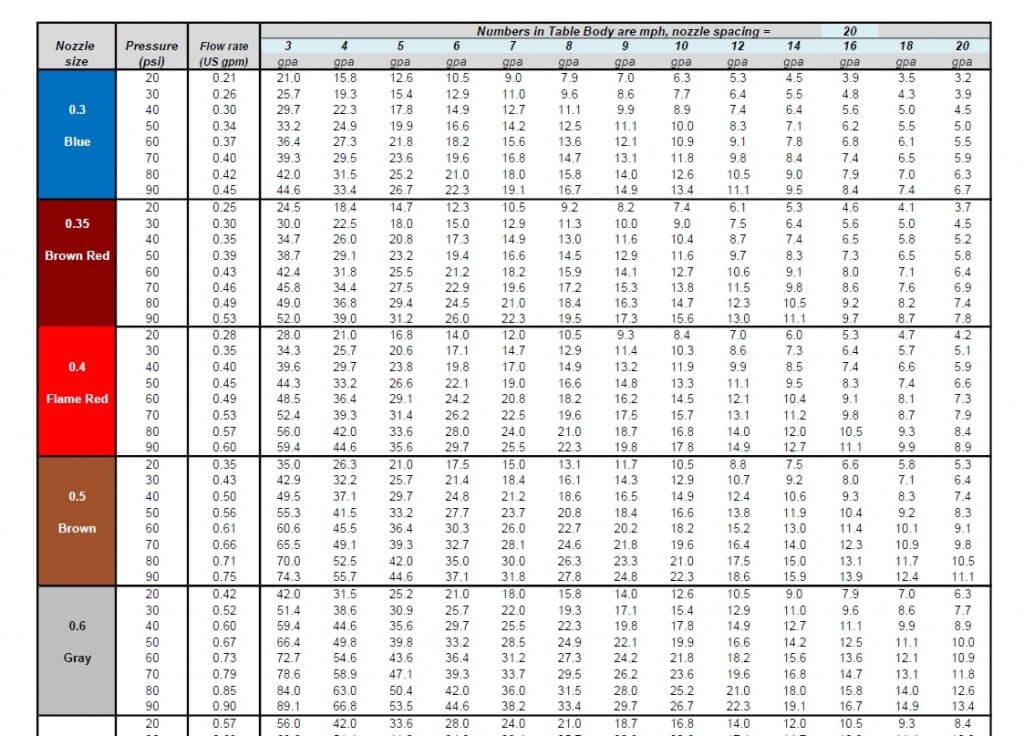
    Try to operate at a spray pressure that’s in the middle of the nozzle’s operating range. For an air-induced nozzle, the range is usually from 30 to 90 psi, so the middle is 60 to 70 psi. That should be the target pressure. Look for a nozzle size that delivers this pressure at your expected travel speed.

    These columns can be used to work out a nozzle’s travel speed range. If a nozzle can be operated between 30 and 90 psi, for example, the corresponding speeds are listed in the same rows in the volume column.

    For example, say you want to apply seven gpa and think that 13 mph would be a good average travel speed.

    Fig 6: Five solutions for the question, “which nozzle to apply 7 gpa at 13 mph?”

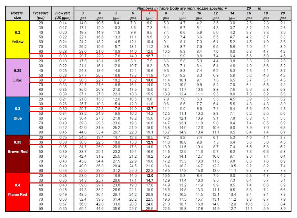
    Move down the seven gpa column, and you’ll encounter a value close to 13 mph five times – the yellow nozzle at 90 psi, the lilac nozzle at 60 psi, the blue nozzle at 40 psi, the dark red at 30 psi, and the red at about 25 psi. Now use the columns to see which of these three best matches your expected travel speed range.

    The yellow nozzle would allow between seven and 12.5 mph from 30 and 90 psi, the lilac nozzle nine to 16 mph, the blue nozzle 11 to 19 mph, the dark red 13 to 22 mph, and the red 15 to 26 mph.

    The best choice for a typical air-induced tip would be the lilac 025 size, since it would meet the target speed of 13 mph at a perfect 60 psi, about right for nozzles of that size, and allowing some travel speed flex on the slower side.

    Some operators try to extend that range, but dropping below 30 psi will likely result in too narrow a pattern, or too coarse a spray quality, so it’s not advised.

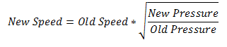
    Note that the three-fold change in pressure from 30 to 90 psi translates to only a 1.73-fold change in travel speed. That’s due to the square-root nature of the relationship, as illustrated by this formula:

    Pressure Formula

    This exercise applies to sprayers with rate controllers that adjust pressure to regulate flow rates. However, if you use pulse-width modulation (e.g. Case AIM Command, Capstan Sharpshooter, Raven Hawkeye, or TeeJet DynaJet) check out this article describing these systems.

    There are a number of apps and websites, usually developed by nozzle manufacturers, which provide similar answers. These are also very useful, and all of them rely on the same formulas used in our new, simplified table. You can go here to download a high resolution version, suitable for framing, in both US and metric units.

  • Increase Sprayer Productivity Without Driving Faster

    Increase Sprayer Productivity Without Driving Faster

    Timing trumps most things in crop protection. A great spray applied at the wrong time isn’t nearly as valuable as a mediocre spray at the right time. So how do we improve our ability to get things done at the right time?

    Often, we try to win races by driving faster. In our last article, we looked at driving speed and concluded that faster speeds can lead to more drift and less uniform deposition. Driving slower can be viewed as a sort of insurance policy: You may not notice the benefits right away, but on days when that extra bit of performance is required, you’re covered.

    So how do you get the job done quickly if you can’t drive faster?  To answer, we have to look to other opportunities for boosting productivity.

    Recently, we built a model to capture all the elements of a normal spray operation that affect timeliness. These were:

    • travel speed
    • boom width
    • tank size
    • water volume
    • field length
    • number of headlands
    • turning speed
    • fill time

    First, we identified a reasonable base condition. For the sprayer, that was a travel speed of 14 mph, a 90’ boom, an 800 gal tank, a 10 gpa water volume, and a 20 minute fill time. Then, we set up a typical field situation, which was spraying a half-mile run on a quarter with two sprayed headlands and a turning speed of 8 mph. Finally, we changed one factor at a time to determine its relative importance.

    Before we discuss the results, let’s make it clear that just because changing some of these factors improves productivity doesn’t mean we’re recommending them! For example, adequate water volume remains an important input that improves coverage and permits the use of low-drift sprays. Larger tanks increase compaction and take more power, and so forth.

    Here’s what we found:

    All productivity values were expressed as acres per engine hour. For this reason, our numbers will be lower than what a typical sprayer monitor reports, most of which calculate acres per spraying hour.

    For the base condition, the sprayer spent 15% of its driving time turning, and 37% of its on-field time stationary (i.e. filling).  For every hour spent on the field, less than half the time (48%) was spent spraying. This resulted in an average productivity of 82 acres/h.

    Increasing the spray speed to 18 mph increased average productivity to 93 acres/h, but it also increased the proportion of time spent turning and loading, resulting in just 40% of the field time spent spraying.

    Decreasing the loading time from 20 to 10 minutes reduced the proportion of field time spent stationary to 23%, covering 100 acres/h at 14 mph. Surprisingly, this was the productivity-winner, resuling in 62% of on-field time spraying.

    We discovered other powerful productivity factors, and chief among them was boom width. A 33% increase in boom width from 90’ to 120’ gave a productivity boost to 94 acres/h, close to the same result as increasing the travel speed to 18 mph earlier. Similar side effects occurred: more time turning, and a greater proportion of time filling, as we saw with faster travel speeds.

    Boom width seems to have some room for growth.  Many smaller European counties use wider booms than we do in North America, for example.  With gps guidance and large fields, we have excellent conditions for their implementation.

    Two other factors that had similar effects to fill time were water volume and tank size. Less water and larger tanks increased productivity by decreasing the fill frequency, with effects similar in magnitude to speeding up the fill time. Decreasing the water volume from 10 to 5 gpa increased productivity to 100 acres/h by decreasing the proportion of time the sprayer was stopped from 37% to 23%. Increasing from an 800 to a 1,200 gallon tank increased productivity to 94 acres/h, again by decreasing the proportion of time spent filling to 28%.

    Taken together, a sprayer with a 120’ boom, a 1,200 gal tank, applying 10 gpa and filling in 10 min had an average productivity of 132 acres/h. And this was achieved without driving faster than 14 mph. If you can string two quarters together and drive a whole mile before turning, that number rises to 145 acres/h, a surprisingly large 13 acres/h gain.

    The perspective of minimizing downtime extends to other tasks, too:

    • Be more prepared for the job by reviewing the product label in advance, noting the correct mixing order.
    • Keep extra nozzles, clamps, and nozzle bodies in the cab.
    • Don’t clean plugged nozzles, replace them.
    • Use low-drift nozzles so a small increase in wind doesn’t shut you down.
    • Ensure all the products needed are on the tender truck (e.g. pesticide, adjuvant, tank cleaner, anti-foamer, etc.).
    • Consider switching to 3” plumbing (pump rates of 300 – 400 gpm are possible).
    • Make sure your inductor won’t be the limiting factor. For example, product pumps can be awfully slow when the product is cold. It might be worthwhile to explore a venturi system.

    Speeding up the fill process is a good idea, but be careful with certain products. Dry materials such as the sulfonyl ureas (e.g. Refine, Express SG, etc.) and some fungicides (e.g. Astound, etc.) require time to hydrate in water so they mix properly. Some operators pre-hydrate these in a smaller tank, while others get an extra tank to pre-mix whole loads and simply transfer them over.

    Also think about the time spent cleaning the sprayer. Thoroughness is important, but perhaps there are efficiencies to be gained there as well, like never letting a sprayer sit after spraying. We’ve written about continuous rinsing, for example, to improve cleaning speed and effectiveness.

    So, the quicker we can spray, while ensuring a quality job, the more effective our crop protection practices will be. We encourage you to use our to determine your best configuration.

    Got a productivity tips to share? Let us know! And remember: In spraying, the race is won in the pits.

    Factor

    Base

    Drive Faster

    Fill Faster

    Spray Wider

    Less Water

    Bigger Tank

    New Sprayer

    Travel Speed

    14 mph

    18 mph

    14 mph

    14 mph

    14 mph

    14 mph

    14 mph

    Fill time

    20 min

    20 min

    10 min

    20 min

    20 min

    20 min

    10 min

    Boom Width

    90 ft

    90 ft

    90 ft

    120 ft

    90 ft

    90 ft

    120 ft

    Water Volume

    10 gpa

    10 gpa

    10 gpa

    10 gpa

    5 gpa

    10 gpa

    10 gpa

    Tank Size

    800 gal

    800 gal

    800 gal

    800 gal

    800 gal

    1200 gal

    1200 gal

    Field Length

    0.5 mile

    0.5 mile

    0.5 mile

    0.5 mile

    0.5 mile

    0.5 mile

    0.5 mile


    Time Turning

    15%

    19%

    15%

    20%

    15%

    15%

    20%

    Time Loading

    37%

    42%

    23%

    42%

    23%

    28%

    19%

    Time Spraying

    48%

    39%

    62%

    38%

    62%

    57%

    61%

    Acres/h

    82

    93

    100

    94

    100

    94

    132