Category: Tables & Apps

Calculators, tables and applications

  • Sprayer Turn Compensation

    Sprayer Turn Compensation

    Turn compensation is a feature in pulse width modulation (PWM) sprayers in which nozzle output matches the boom’s speed during a turn. When turning, the inside and outside of a boom travel at different speeds, resulting in over-dosing on the inside and under-dosing on the outside. Read about PWM systems here, here, and here.

    The degree of the problem depends on the inside turn diameter. Clearly, the tighter the turn, the more severe the over-and under-dosing. The ability of a PWM sprayer to compensate also depends on the turn tightness, as well as the Duty Cycle (DC) the system is operating at during the turn.

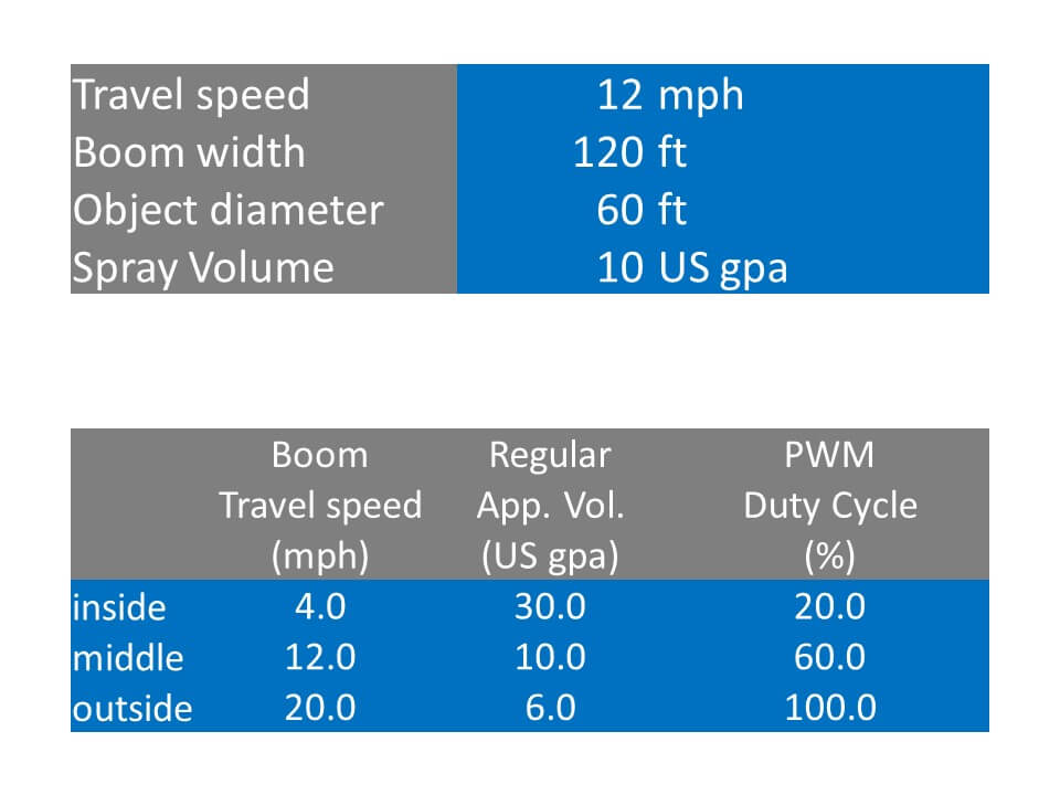
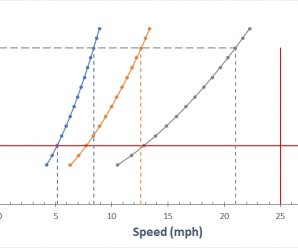
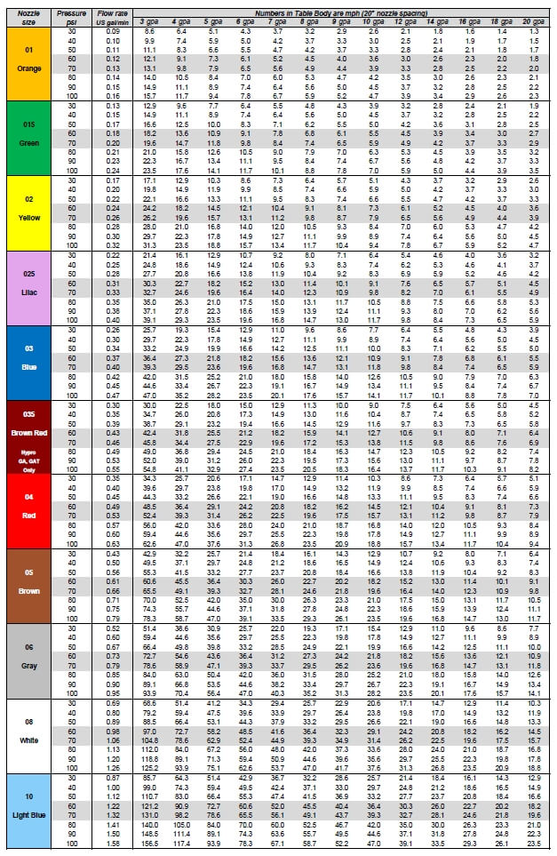
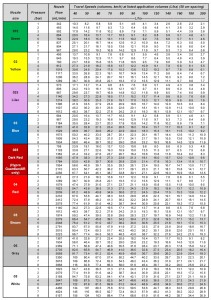
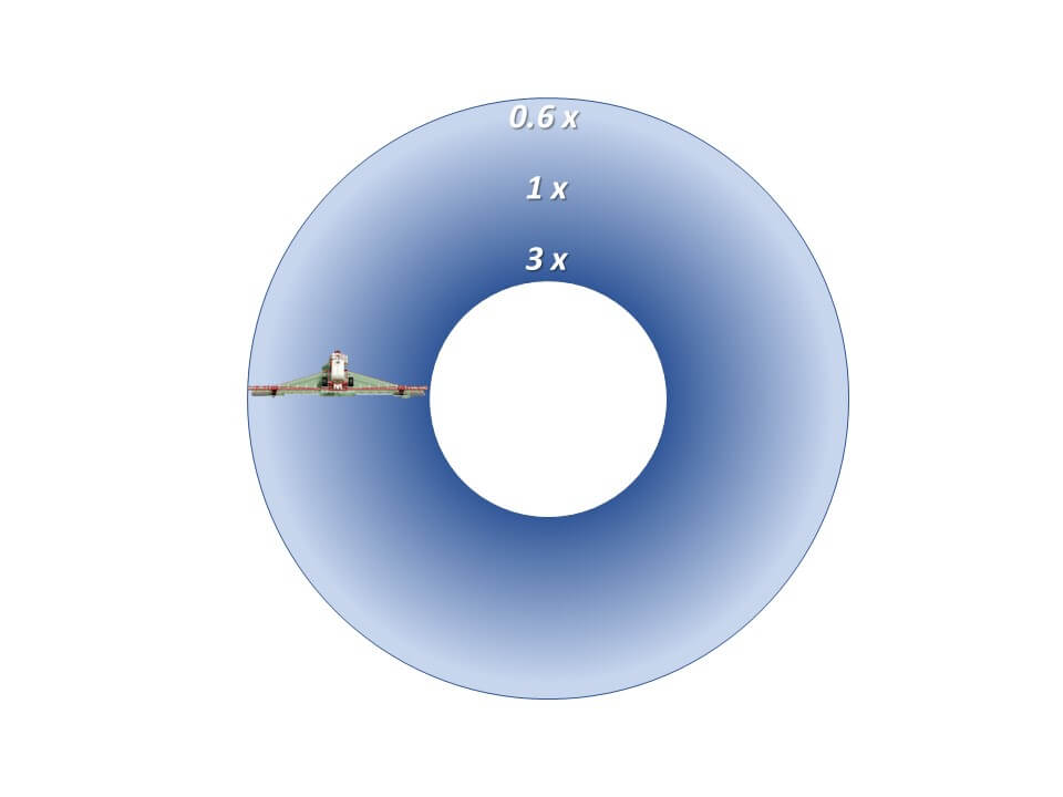
    In the above example, a 120 ft boom makes a turn around an object with a 60 ft diameter. Assuming a 12 mph speed and an application volume of 10 gpa, the inside of the boom travels at 4 mph and applies 30 gpa, or 3x. On the outermost nozzle, the speed is 20 mph with an application volume of 6 gpa, or 0.6 x. A sprayer operating at 60% DC would be able to correct the application in this turn by operating at 100% DC on the outside and 20% DC on the inside.

    But completing the turn at other DCs may be problematic. In this case, lower sprayer DC would require the inside DC to operate below 20%, which may not be possible, depending on the system. Conducting the turn at higher DC would prevent the outer boom from meeting the flow requirements, resulting in under-dosing.

    Optimizing the benefit of turn compensation requires the operator to enter the turn at a DC that meets the objectives. Is it more important to prevent under-dosing of the outside perimeter? If so, slow down in the turn (reducing DC) and maximize the extra capacity at the outside of the boom, possibly at the cost of over-dosing the inside.

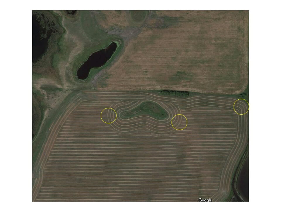
    The agronomic benefit of turn compensation is to provide sufficient pesticide dosage where it’s needed. It’s been reported that repeatedly applying sublethal herbicide dosages at the same site can lead to the development of polygenic resistance in some outcrossing weed species. These areas are likely to occur at the outside boom location of a permanent landscape feature that the sprayer moves around year after year.

    Turn compensation is a valuable feature in all agricultural operations where input distribution uniformity is important. Spraying is no exception, and PWM makes it possible.

  • Nozzle Sizing and Calibration Charts

    Nozzle Sizing and Calibration Charts

    Need to find the right nozzle size for your application?  Sometimes a simple chart is the easiest way to figure things out.  Print it and place it in your sprayer cab.

    In this chart, identify your water volume along the top row, and follow the column until you encounter the travel speeds you’re interested in.

    Once you’ve encountered your travel speed, move along the row to the left to identify the nozzle size and spray pressure.

    Make sure that your travel speeds are achieved at a pressure that’s right for the nozzle you’re using. For most air-induced nozzles, this will be about 60 to 70 psi (highlighted).

    Once you’ve decided on a nozzle size, the travel speed column for that size becomes the travel speed range at various pressures. Avoid operating a low-drift spray below 30 psi – its pattern will be too narrow and likely its spray quality will be too coarse for good results.

    Click on the images or text below to download a high quality pdf version of each chart, starting from the top with US, 15″ spacing, then US, 20″, then US 30″, then metric, 50 cm. Print, laminate, and place them in your sprayer cab.

    Calibration Chart (US, 15 in)

    Download Application Chart (US units, 15″ spacing)

    Calibration Chart (US, 20 in)

    Download Application Chart (US units, 20″ spacing)

    Calibration Chart (US, 30 in)

    Download Application Chart (US units, 30″ spacing)

    Application Chart 2015 (metric)

    Download Application Chart (metric, 50 cm spacing)

    Make your own chart using this Excel Template.

  • Diluting 20,000-Fold with a 30 Gallon Remaining Volume in a 1,200 Gallon Tank

    Diluting 20,000-Fold with a 30 Gallon Remaining Volume in a 1,200 Gallon Tank

    (This short article is an addendum to this article)

    Our goal in this example is to dilute by a factor of 20,000.

    The maximum amount of dilution possible with a 1,200 gallon tank and a 30 gallon remainder is 1200/30=40.

    The formulae:

    Dilution per Rinse = final dilution ^(1/# of rinses)

    Rinse Volume = (dilution per rinse * remaining volume) – remaining volume

    • One rinse diluting by 20,000 – impossible with a 1,200 gallon tank (max achievable is 40-fold);
    • Two sequential rinses, each diluting by a factor of 20,000^(1/2) = 141. Also impossible with a 1,200 gallon tank;
    • Three sequential rinses, each diluting by a factor of 20,000^(1/3) = 27. A volume of 780 gallons can do this  (27*30)-30=780 gallons. For three rinses, the total volume is 2,340 gallons.
    • Four sequential rinses, each diluting by a factor of 20,000^(1/4) = 12. A volume of 330 gallons can do this, for a total volume of 1,320 gallons;
    • Five sequential rinses, each diluting by a factor of 20,000^(1/5) = 7. A volume of 180 gallons can do this, for a total volume of 900 gallons;
    • Six sequential rinses, each diluting by a factor of 20,000^(1/6) = 5.2. A volume of 126 gallons can do this, for a total volume of 757 gallons.

    Second, let’s assume the operator is prepared to prime the boom where it doesn’t harm soybeans. Now the first new product tank takes care of the last dilution, lowering the cleanout dilution requirement by 1,200/30 = a factor of 40. Now the cleanout dilution requirement is only 20,000/40 = 500.

    • One 1,200 gallon tank rinse can only achieve 40-fold dilution.
    • Two rinses, each diluting by 500^(1/2) = 22. Rinse volumes of 640 gallons are sufficient, for a total of 1,280 gallons.
    • Three sequential rinses, each diluting by a factor of 500^(1/3) = 7.9. A volume of 210 gallons can do this, for a total volume of 630 gallons;
    • Four sequential rinses, each diluting by a factor of 500^(1/4) = 4.7. A volume of 112 gallons can do this, for a total volume of 448 gallons.