Tag: rinse

  • Installing a Continuous Rinse System

    Installing a Continuous Rinse System

    Cleaning, flushing, triple-rinsing… whatever you call it, sprayer sanitation is a time-consuming and distasteful task.

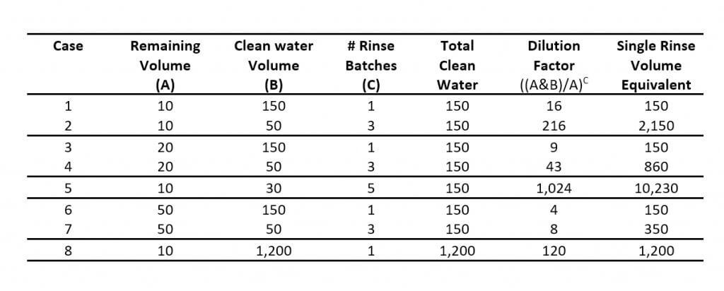
    Methods vary, but they generally span from the classic triple rinse (30-45 minutes) to a full tear-down and decontamination (many hours and likely an overnight soak). The operator decides how much time and effort to invest depending on the chemistry they’ve just used and the crop they intend to spray next. Learn more about the power of dilution in this article and in this article.

    Unfortunately, two facts are certain:

    1. At minimum, operators should rinse the sprayer at the end of each day… and they generally don’t.
    2. It is only after spraying a sensitive crop that the operator truly knows whether the sprayer was cleaned sufficiently.

    Continuous Rinsing

    We’ve promoted Continuous Rinsing as a viable alternative to Triple Rinsing in previous articles (see here and here). Executed correctly, the method:

    • greatly reduces the time required,
    • is as effective,
    • eliminates operator exposure, and
    • reduces potential environmental contamination.

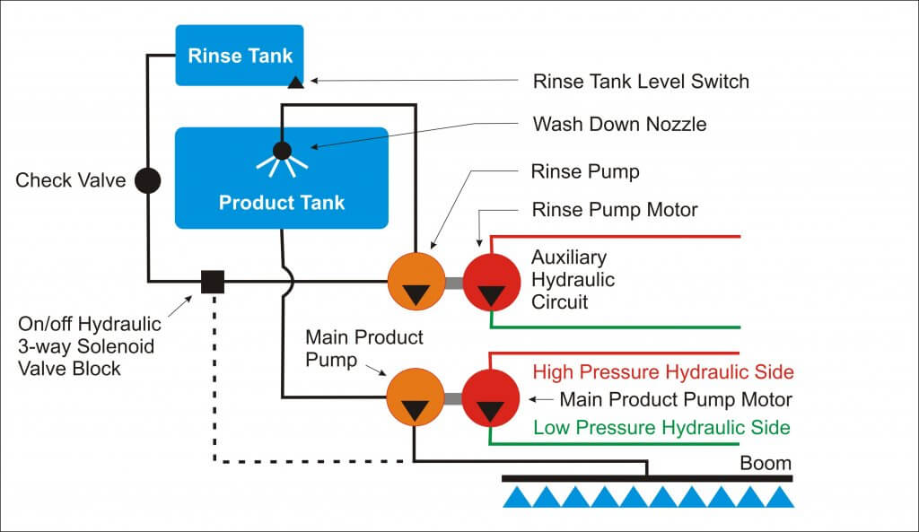
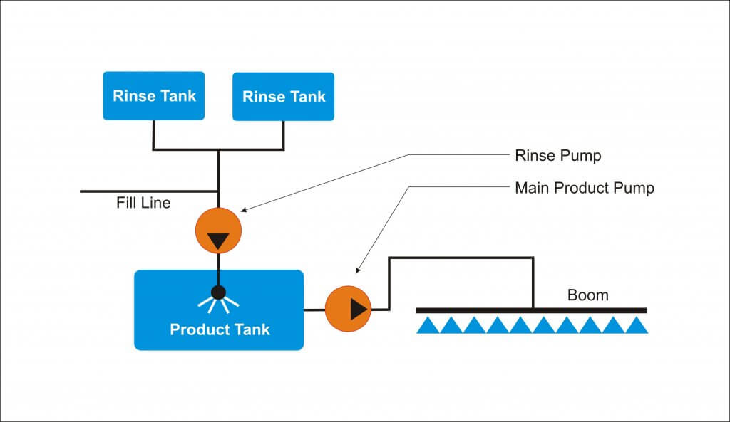
    Continuous rinsing requires the installation of a dedicated “rinse pump” to transfer clean water to the product tank from the rinse tank via the wash-down nozzles. This permits the main product pump to operate simultaneously, emptying the product tank and spraying the rinsate out the boom.

    Imagine your sprayer empties at the end of the row. You position the sprayer at a headland or a row you sprayed earlier. A toggle switch in the cab engages the rinse pump and the wash-down nozzles start spraying clean water into the product tank. You then resume driving and spray until the rinse tank is empty. During the process, any solution in the return/bypass line is quickly diluted, and any standing volume in the system is displaced by clean water.

    It takes five minutes and you never left the cab.

    Remember: Rinsing can dilute residue to ~2-5% in most of the sprayer plumbing, but it is not intended to replace the more rigorous decontamination process. Closed circuits, filters and dead-end plumbing can still harbour residue >15%.

    Installation

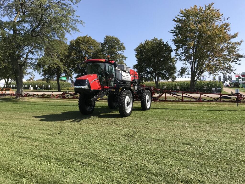
    Working with GreenLea Ag Center in 2017, we installed a Continuous Rinse system on a Case IH Patriot 4440. It has a 1,200 gal. product tank, a 140 gal. rinse tank and a 120 foot boom. A parts/price list for the Patriot installation appears at the end of this article.

    Additionally, we have included the parts/price list from our 2016 HJV Equipment installation on a RoGator 700, which had a 700 gal. product tank, 50 gal. rinse tank and a 90 foot boom.

    Still further, we have included three homegrown solutions from operators that developed their own continuous rinse systems.

    Sizing the Rinse Pump

    It is very important that the rinse pump has the capacity to operate the wash-down nozzles and still supply clean water at a rate approximately equal to the rate at the boom. Basically, “in must equal out”. If the rinse pump supplies too much clean water, the volume rises in the product tank and efficiency is reduced. If it cannot supply enough, the main product pump will lose suction and not function correctly.

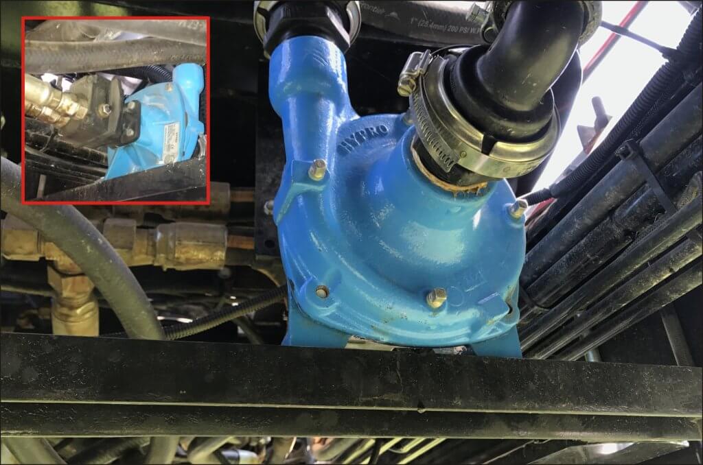
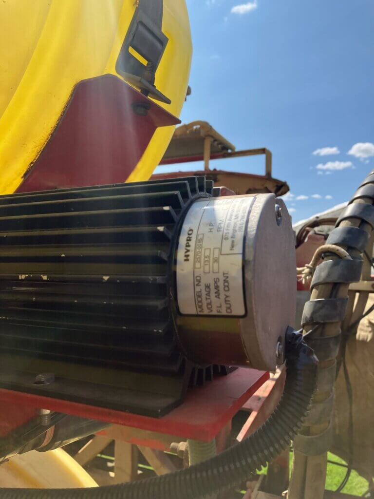
    We installed a Hypro 9303C-HM1C centrifugal pump (max flow rate of 114 gpm at 130 psi), matching the make and model of the exiting product pump. A length of channel was installed on the chassis to mount the pump and close-coupled hydraulic rinse pump motor, and a valve block.

    Really, electric pump installation is easiest. An alternate pump that has been used is this one from Pattison Liquid. For added benefit, it’s a chem transfer pump that can handle the pesticide formulations. If the pump doesn’t give enough flow, a second one can be installed parallel to double the flow.

    Hydraulics

    Let’s being with advising caution: If you are uncertain about your hydraulic capacity (and tightly designed systems rarely have extra) then consult with a manufacturer-certified service technician, or consider an electrical alternative.

    For the Patriot, the auxiliary hydraulic circuit was used to drive the hydraulic rinse pump; we piggy-backed off of that existing system. In this case, Continuous Rinsing increased the load on the auxiliary hydraulic circuit, but only marginally, so performance was acceptable.

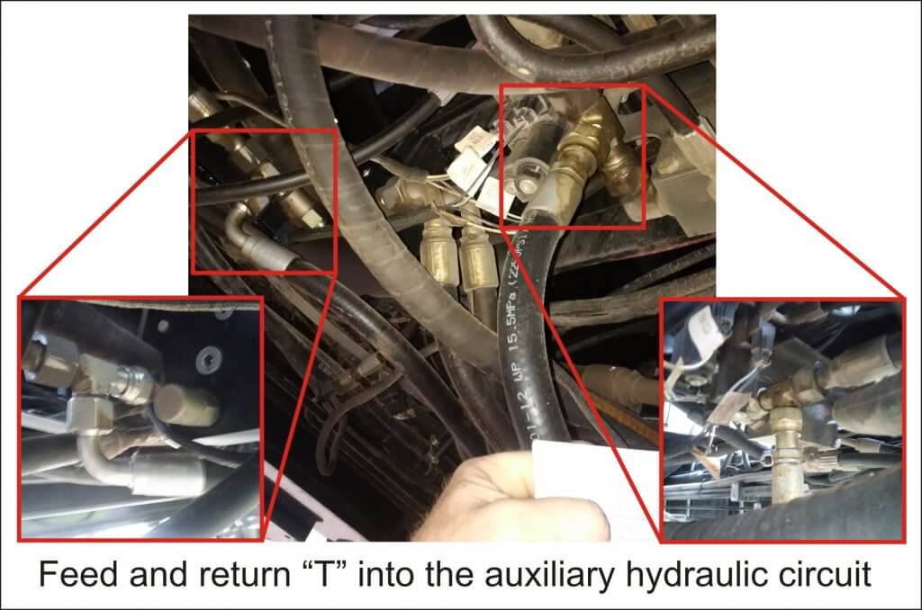
    We drew that hydraulic flow directly from the auxiliary pump output using a ‘T’ piece to ensure full pressure was available when needed. Then we broke into a common low pressure return manifold using another ‘T’ piece to provide the return flow.

    Originally, we were concerned that robbing too much hydraulic flow could compromise sprayer operations. We therefore exchanged the hydraulic motor that came with the pump for one that required less hydraulic flow. However, the pump operated at such a high speed that the rinse tank was drained in two minutes! We felt this would not give the operator enough time to make minor adjustments (see the “Avoid Airlock” section later in the article). We also felt the rinsate would not have enough time to hyrdate any residue in the tank and lines. We therefore returned to the motor that came with the pump, slowing the pump and bringing our rinse time to approximately five minutes.

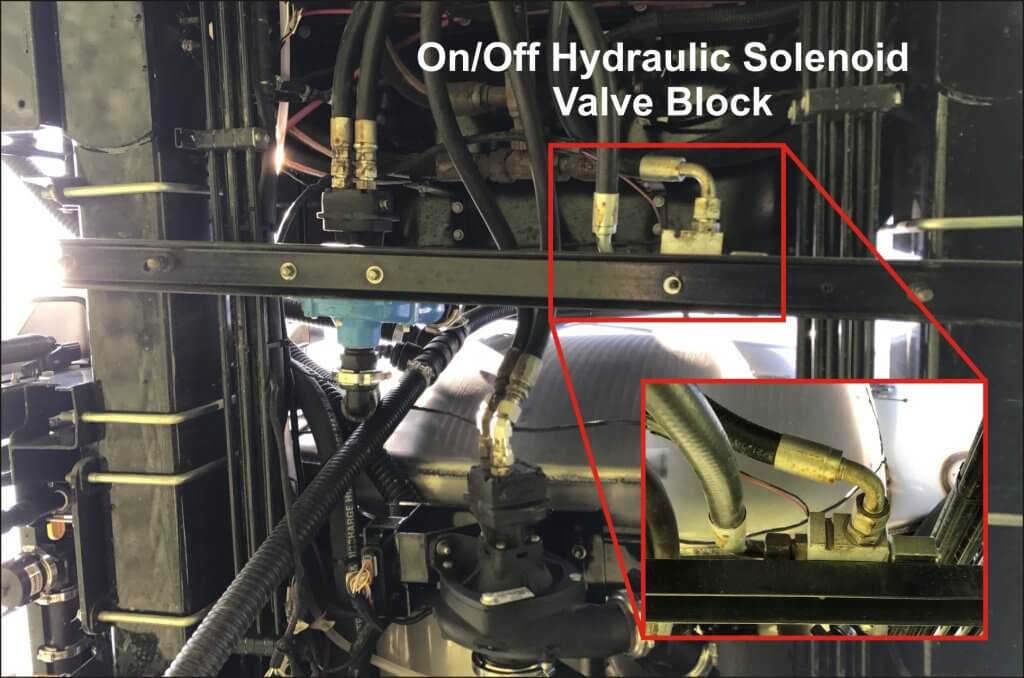
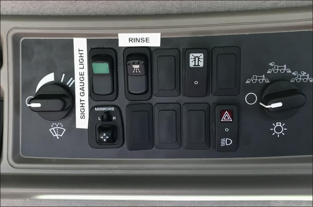
    We installed an on/off hydraulic control valve block and solenoid controlled by a toggle switch in the cab. When the rinse switch was engaged, 12 volt DC opened the solenoid, allowing hydraulic oil from the auxiliary pump to turn the rinse motor, which in turn powered the rinse product pump.

    Avoid Airlock by Balancing Flow

    While Continuous Rinsing works well with an unbroken stream of clean water, there is demonstrated benefit to allowing the pump to draw a small amount of air. The bubbles are reputed to scrub the lines more effectively than water alone. It is possible that the new Hypro 9307 series centrifugal pump, which claims to eliminate dry run, would facilitate this.

    However, avoid excessive cavitation or airlock of the main product pump. This will damage the pump seals and interfere with pump suction. If the main product pump is a piston-diaphragm pump, avoid losing the prime by letting a small volume of rinse water build up in the product tank before spraying the rinsate.

    Maintaining the balance between the supply from the rinse pump, and demand by the product pump, will take careful trial and error. If the sprayer employs a rate controller, speeding up or slowing down travel speed is a means for making adjustments to match the two flows. Alternately, an operator can adjust the pressure regulator manually. Remember, the nozzles won’t need to work optimally so you have the option to use fairly low pressures to match flows.

    In the case of an operator applying 28-0-0 using dribble bars or fertilizer nozzles, there is likely too much flow at the boom for the rinse pump to keep up. While we have not tried it, but as long as there was sufficient volume in the clean water tank, it might be possible to rinse the boom section by section, starting with the outside sections and moving in towards the centre.

    Lessons Learned

    The installation was a learning process, during which we noted the following:

    • At first, the rinse tank slowly emptied through the rinse pump, even when it wasn’t in use. We prevented this by installing a 10 psi check valve between the pump and main tank.
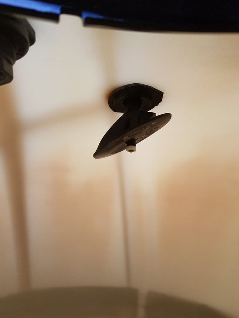
    • The rinse pump ran dry and burned the seals when the operator forgot to turn it off after the rinse tank was empty. We considered a timer or alarms to prevent this, but chose to install a level sensor (essentially a float) which would cut the 12 Volt DC feed to the on /off solenoid, effectively turning the system off when the rinse tank was empty. Note: the sensor is not in the parts list – it was purchased for ~$10.00 CAD from Amazon.
    • When deciding where to draw hydraulic flow to run the rinse pump, we first tied into the main hydraulic circuit (i.e. not the auxiliary). This negatively affected both steering and boom control. Beware drawing flow from critical safety systems such as steering.

    Future Development and Other Advantages

    GreenLea was exploring an option to use the rinse pump to bypass the product tank, and flow directly to the boom. This can be accomplished by teeing an electrical 3-way ball valve just after the pump to allow flow directly from the rinse tank (see dashed line in the flow schematic shown earlier in the article). Imagine being rained out, or having excess mix left in the tank at the end of the day. This system would allow the dilution of any corrosive chemical from a sensitive precision application system without losing or contaminating the spray tank. It should be noted, however, that high precision spray systems (e.g. AIM Command, Pro and Flex) would still require the operator to open the boom flush valves manually to allow the boom purge.

    Growers have suggested the system might also be used to get a sprayer to end of a row if it threatens to run empty before completing the pass. A small volume of clean water added to the tank would displace the 15-30 gallons of unusable volume and stretch the application. Be aware that this would also dilute the product due to the agitation/bypass and should only be considered when a minute or less of additional spray is required.

    Homegrown Solutions

    Tyler Patriot (Electrical)

    David Kucher (@DavidKucher) from Saskatchewan installed Continuous Rinse on his Tyler Patriot (75 foot boom, 800 gal. product tank).

    Here’s what he had to say:

    The rinse system I was using on my sprayer previously involved a lot of time and effort. Plus, the quality of job it did was sometimes imperfect (I keep pictures on my phone of a canola crop that was damaged because of a poor rinse job from a few years ago). The old system used the main product pump to rinse, so there was a bunch of valves under the sprayer that needed to be turned, and the pump had to reprime for each rinse. It was tedious.

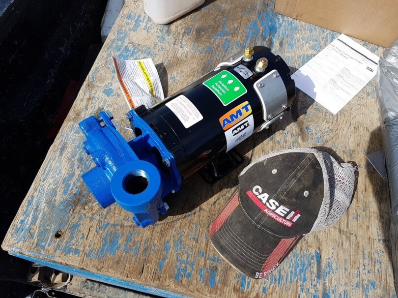
    Uncertain about the hydraulics, David elected to use an electrical pump, but had difficulty finding one that would produce enough pressure and flow. Most electric pumps were too small and it would have taken more than one, plumbed in parallel, to achieve the volume numbers required. However, David found a high-flow 489G-95 AMT High Head Washdown Pump (1 HP, 1-1/4×1 IN/OUT, 12 VDC,Cast Iron,Buna-N) which he got from the US for about $1,200.00 CAD. Max flow was 56 gpm.

    Note: In 2020 this pump model changed to the 12DC-95.

    He removed the majority of plumbing, valves, and related complexity from the old rinse system. The Continuous Rinse was comparably simpler and isolated from the rest of the sprayer plumbing. It just involved a fill line from his two clean water tanks, the new rinse pump, and the existing rinse nozzle inside the product tank.

    When the product tank empties, David holds down a push button dead-man switch he installed to activate the rinse pump. If he wants to do a more thorough job, he flushes the product tank and plumbing for about two minutes, then stops, gets out and opens the boom end valves. Then he climbs back in and does another one minute flush.

    Approximately 30 gallons of water go through on each flush and my only issue is that I waited so long to install the system.

    Author’s note: Positive displacement electrical pumps (which have zero risk of seal loss) are reasonable alternatives to centrifugal pumps. Depending on the size of the sprayer, multiple pumps plumbed in parallel can provide sufficient flow. We elected to use two Hypro electric roller pumps (model 4101 N-H) for the 2016 RoGator 700 installation. Cheaper, low amperage 12V diaphragm pumps from Delevan and FLOJET with capacities of 5-8 gpm are also available.

    John Deere 4830 (Hydraulic)

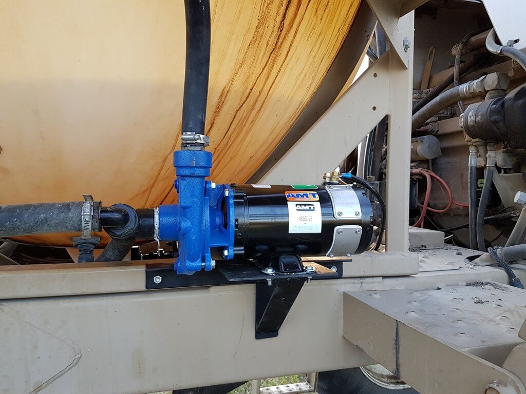
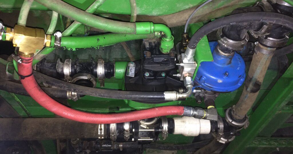
    Russ Enns (@EnnsFarms) from Saskatchewan installed a Delavan HD Magnum 125 hydraulic driven pump (1-1/4” suction, 1” discharge, 5-7 gpm of hydraulic flow). He mounted it on the same mounting plate as the main product pump, just on the opposite side, using the same bolt holes.

    It was tied hydraulically to the main product pump, so the rinse pump could only run when the product pump was operating. The hydraulic supply from the sprayer went through an electric/hydraulic block via a solenoid resting in the closed position. A rocker switch in the cab used 12V to activate the rinse pump from the cab. Return hydraulic pressure from the rinse pump was tee’d into the main solution pump hydraulic return.

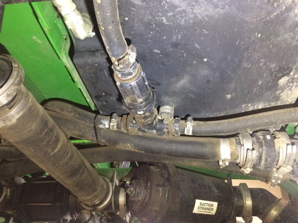
    The clean water intake for the rinse pump was tee’d into the factory rinse tank. The discharge side of the rinse pump was plumbed to a check valve and tee’d into factory tank rinse system. Here’s the discharge line, check valve and tee into factory rinse (below).

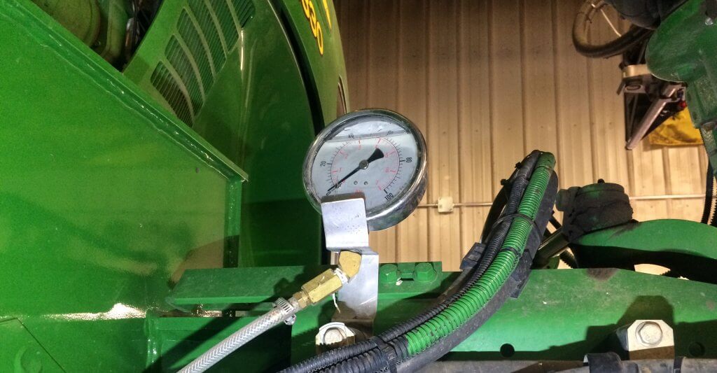
    Russ mounted a large pressure gauge on front right axle to monitor rinse pressure. It’s easy to see from the cab, and easy to tell from the pressure when the rinse tank is empty.

    In this case, Continuous Rinse is used in tandem with an Accu-volume tank gauge so Russ could monitor the level in the main product tank from the cab. Depending on the nozzles being used, he found that the rinse pump supplied clean water faster than the rinsate could be sprayed.

    So, after finishing a field (or changing chemical, etc.) Russ turned on the rinse system while spraying the rinsate out on the field. The Accu-volume alerted him if clean water was accumulating in the product tank. If it got to ~20 gallons, he would briefly suspend the rinse pump while spraying to allow the level to drop. Then, he would start the rinse pump back up. He repeated this process until the clean water tank was empty.

    Russ had many of the main components on hand, but estimates replacement value at ~$1,200.00 CAD. He noted that while installation was straight-forward, he originally piggy-backed the rinse pump’s hydraulic supply off the main solution pump, and it didn’t work correctly. We did that too, Russ 🙁

    “Time savings and environmental considerations are the biggest benefit of this system to me. Being able to finish spraying a field, and immediately start rinsing and spraying the diluted solution is a huge time saver. I feel it’s a far more thorough rinse and a better/quicker dilution rate compared to how I previously handled rinsing and spraying out the diluted solution. Another benefit is that even though it’s plumbed into the factory rinse, the factory rinse system can still be used normally if for some reason the continuous rinse pump quits.”

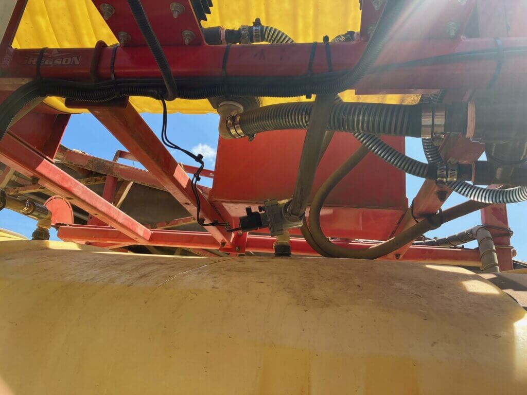
    Gregson Trailed (Electrical)

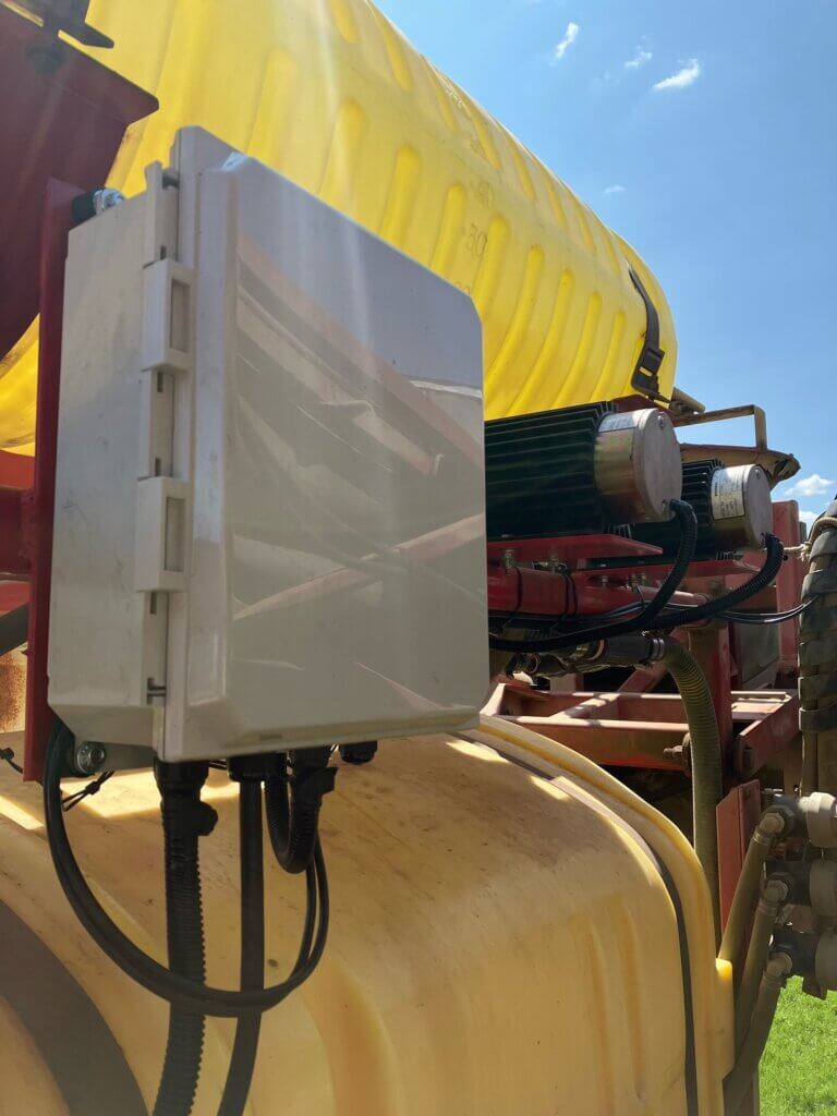
    Continuous Rinse isn’t only for grains and beans. Matthew Droogendyk installed two 12v pumps on his trailed vegetable sprayer that matched the flow of the main pump. They had an electrician install a box for switching the the pumps and two solenoid valves on at the same time.

    They noted an issue when trying to prime the main pump after emptying the tank. If the tank was sprayed completely empty, the main pump took time to get primed again. This affected rinsing time as well as the balance between supply and demand. Through trial and error they determined that running the rinse pumps for 1 minute (~15 gal) gave enough time to rid the main pump of air. Then the flows matched at about 15 gpa. Re-priming took about 5 minutes, and then an additional 2 or 3 to rinse using about 45 gallons of clean water. They found there was no need to replace their original tank rinse nozzles.

    Tank Rinse Nozzles

    One of the challenges of installing continuous rinse is ensuring the tank rinse nozzles are capable of rinsing the entire solution tank interior at potentially low pressure and low flow. In 2019, Lechler released the ContiCleaner range of rinse nozzle. Four ISO colour-coded nozzles capable of operating from 2-5 bar (29-72.5 psi), with flows from 6.5-32.3 L/min. (1.7-8.5 gpm). This will enable operators to better match the rinse nozzle(s) to the clean water pump. Be aware they are very difficult to source in North America. We tried and weren’t able to get them.

    Parts / Price List

    The following two parts/price lists are in Canadian Dollars. They do not include tax or labour and prices change depending on where and when parts are purchased. As you have read from the operators that installed their own Continuous Rinse systems, there are many possible solutions, so these lists are provided only for reference. Click the link to download a PDF.

    Learn More

    So far we’re aware of two Ontario companies and one Belgian company with experience installing the system. We will expand this list over time.

    Before contacting them, have the following information on hand:

    • Sprayer tank volume (both product and rinse, if applicable)
    • Boom length
    • Nozzle spacing
    • Largest nozzles mounted/used on the sprayer (excluding fertilizer nozzles)
    • Power available on sprayer (e.g. 12V available? Max amp? Hydraulic capacity?)

    Thanks to Russ Enns, David Kucher and Matthew Droogendyk for sharing their install stories. Thanks to Adam Beaumont and Ehrin Frid for the Case IH and RoGator installations, and to Mike Cowbrough (@cowbrough) of OMAFRA and the Ontario Soil and Crop Improvement Association for collaborative support.

  • Cleaning an airblast sprayer

    Cleaning an airblast sprayer

    Next to sprayer math, cleaning the sprayer is one of the more distasteful aspects of airblast spraying. It’s time-consuming, you never really know when you’re finished, and sprayer manufacturers and pesticide labels offer only limited guidance.

    Clean sprayer rinsate often looks and smells exactly like contaminated sprayer rinsate.

    When airblast sprayers are not cleaned as often or as thoroughly as they should be, it creates problems:

    • Unnecessary operator and environmental exposure.
    • Residue in (or on) the equipment can damage sprayer components.
    • Residue can cause physical or chemical incompatibility issues with future spray mixes.
    • Carry-over can deposit damaging or unlabelled residues on crops.
    Keeping the sprayer clean, inside and out, as part of the spray day. K. Bell is pictured giving his FMC a bath. This picture was staged – he normally wears PPE and so should you.
    Keeping the airblast sprayer clean, inside and out, as part of the spray day. Ken Bell is pictured giving his FMC a bath. This picture was staged – he normally wears PPE and so should you.

    Dr. Tom Wolf (Agrimetrix Research and Training), defines cleaning as two processes. Rinsing is the dilution of any remaining spray solution. Cleaning is rinsing with additional steps to decontaminate sprayer components (e.g. filters, nozzles).

    Rinsing

    1. Rinse ASAP

    Don’t let residue sit in (or on) the sprayer, even if you plan to use the same product the next day. Multiple studies have shown that products adsorb onto, and absorb into, plastic and rubber parts. They form hard-to-clean residues when left to dry.

    Think about cleaning oatmeal or egg yolk off dishes – it’s far easier if you clean them before they dry. Rinse right away, while the sprayer is still wet.

    2. Minimize the volume remaining in the sprayer

    Experience, sprayer math, and familiarity with airblast sprayer design helps minimize the volume remaining in the sprayer. Rate controllers and volume-monitoring systems (e.g. Ontario’s Accu-Volume) provide real-time feedback so the operator can speed up or slow down to empty in the right place. Minimizing any remaining volume makes rinsing far more effective.

    Even an “empty” sprayer can still retain several litres of standing volume in the sump and lines. Operators should know this volume. Never Drive-and-Drain to empty standing volume onto the ground.

    Standing volume from the booms allowed to drain to a holding tank via the bottom nozzles.

    3. Dilute the remnant: The Triple Rinse

    Rinsing the system multiple times with low volumes (aka The Triple Rinse) is more effective at reducing pesticide concentration than a single, high-volume rinse. See for yourself using this clever dilution calculator.

    Once the sprayer is “empty”, use clean water to fill the tank to 10% of its capacity (or add 10 parts water to one part standing volume) for the first rinse. The use of such low volumes may not be possible with centrifugal systems where the tank must be filled above the top of the pump for priming. Know your sprayer design.

    Agitate and circulate it through the entire sprayer for a few minutes. Spray out the rinsate and repeat the process two more times. Where do you perform this? Where does the rinsate go? Read on.

    A wooden sprayer tank. You know that had to be tough to clean thoroughly.
    A wooden sprayer tank. You know that had to be tough to clean.

    Where does the rinse water come from?

    Nowadays, all airblast sprayers should include an onboard tank-rinse system consisting of a clean water tank and tank-rinse nozzles inside the tank. They may even include a pressure wand to rinse the exterior.

    Sadly, most airblast sprayers do not have these features. But, aftermarket rinse kits are available. If you are considering installing a rinse system, check out the continuous rinse system.

    Left- Product-pump-powered water tank, Right- external-pump-powered water tanks. Images from Paolo Balsari’s (DiSAFA) “Sprayer Cleaning: Importance and Phases” at AAB Sprayer Cleaning Workshop, Oberbozen, Italy. October 2019.
    The Hol features a separate 150 L tank to supply clean water to its automatic tank rinse system.
    The Hol features a separate 150 L tank to supply clean water to its automatic tank rinse system.

    Alternately, the clean water for this process can be carried on a support vehicle or sourced from holding tanks strategically-located near the planting.

    Where to rinse

    Precautions must be taken to ensure rinsing is performed away from wells or open water. It is best to perform the triple rinse in the crop that was just sprayed. The dilute rinsate can be flushed through the lines and sprayed out through the nozzles onto the crop. You can choose to overspray treated areas again at a lower dose (label permitting), or use a hedgerow or target row that has been set aside for this purpose.

    As regulatory agencies concerned with environmental contamination re-evaluate chemistries critical to horticulture, it becomes even more important for airblast operators to manage rinsate responsibly.

    While it is best to rinse the sprayer exterior in the planting as well, most return to the farm. Too often, the entire rinsing procedure takes place on-farm, on crushed gravel. This creates point-source contamination: a leading source of off-target pesticide movement. Washings should be secured (e.g. on an inflatable or permanent loading/mixing pad.

    Cleaning an airblast sprayer on an inflatable pad. Images from Victoria Nelissen’s (pcfruit, Belgium) “On-farm systems to avoid point pollution” at AAB Sprayer Cleaning Workshop, Oberbozen, Italy. October 2019.

    In Europe, operators are encouraged to collect contaminated rinsate for safe disposal. There are four systems in use:

    • Bioremediation – Employs a bio-active matrix (E.g. Biobed).
    • Evaporation / Dehydration – Residue following evaporation is collected and disposed of (E.g. Heliosec).
    • Physico-chemical – A combination of filtration and active carbon.
    • Photocatalytic – Photo degradation (E.g. Phytocat).

    Cleaning

    A complete cleaning is required prior to long-term storage, or when residues from previous applications are known to cause physical or chemical antagonism with scheduled applications. Perform the following steps after a complete triple rinse:

    One. Remove the suction and in-line screens. Remove nozzle strainers and nozzle tips. These will be inspected and cleaned shortly.

    Two. Fill the tank about 1/2 full of water and add an appropriate tank cleaning adjuvant. For example, ammonia at 3%/100L water will raise the pH and helps remove those products whose solubility benefits from this. A detergent at 1.0 kg /150 L water will remove the oily layer formed by EC formulations. Commercial cleaners like All Clear or Cleanout conveniently combine these properties in one jug. Be aware that adding a surfactant or a commercial cleaner can generate a lot of foam, so have de-foamer handy.

    Note: Ammonia cleaner products do not “neutralize” pesticides; they raise the pH, improving the solubility of some products. Do not use chlorine bleach! It is not as effective a cleaner as ammonia and can form chlorine gas when mixed with ammonia-containing liquids.

    Three. Collect a bucket-full of cleaner solution from the tank. Using a brush, clean the suction and in-line screens, and the nozzle strainers and tips.

    Four. Meanwhile, agitate and circulate it the cleaner solution through the entire sprayer for five to 10 minutes. Open and close any lines or valves during this process to ensure everything is exposed to the rinse.

    Five. You might spray a small volume through the booms, but drain the vast majority through the plumbing system. Collect some for cleaning the exterior of the sprayer.

    Six. Clean the exterior of the sprayer. High pressure washers and scrubbing with a push broom works well. Studies in Europe have shown the vast majority of residue is found on the sprayer head (i.e. fan outlet and boom area).

    Pressure washers are handy tools on a farm, and they’re fun to use, too. However, they can cause a great deal of damage if they are used to wash delicate things like engine parts, electronics housings, or sealed bearings. Use caution!
    Pressure washers are handy tools on a farm, and they’re fun to use, too. However, they can cause a great deal of damage if they are used to wash delicate things like engine parts, electronics housings, or sealed bearings. Use caution when power washing an airblast sprayer.
    Relative external contamination on a low profile axial airblast sprayer. Image from Paolo Balsari’s (DiSAFA) “Sprayer Cleaning: Importance and Phases” at AAB Sprayer Cleaning Workshop, Oberbozen, Italy. October 2019.

    Seven. Rinse it all off. Replace all parts unless preparing for long-term storage.

  • Biobeds for Pesticide Waste Disposal

    Biobeds for Pesticide Waste Disposal

    One of the most challenging aspects of a spray operation is the disposal of leftovers or rinsate containing pesticides. Let’s be honest, too much of it is drained onto the ground in a corner of the yard or the field. Nobody’s happy about that, nobody’s proud of it, but what are the alternatives?

    Waste disposal is a skeleton in the closet of the pesticide industry. One of the problems is the time-consuming nature of sprayer cleaning, and the lack of clear guidelines on product labels that pass the buck.  Too often, the applicator is asked to “act in accordance with provincial or state guidelines”, which is essentially a dead end.

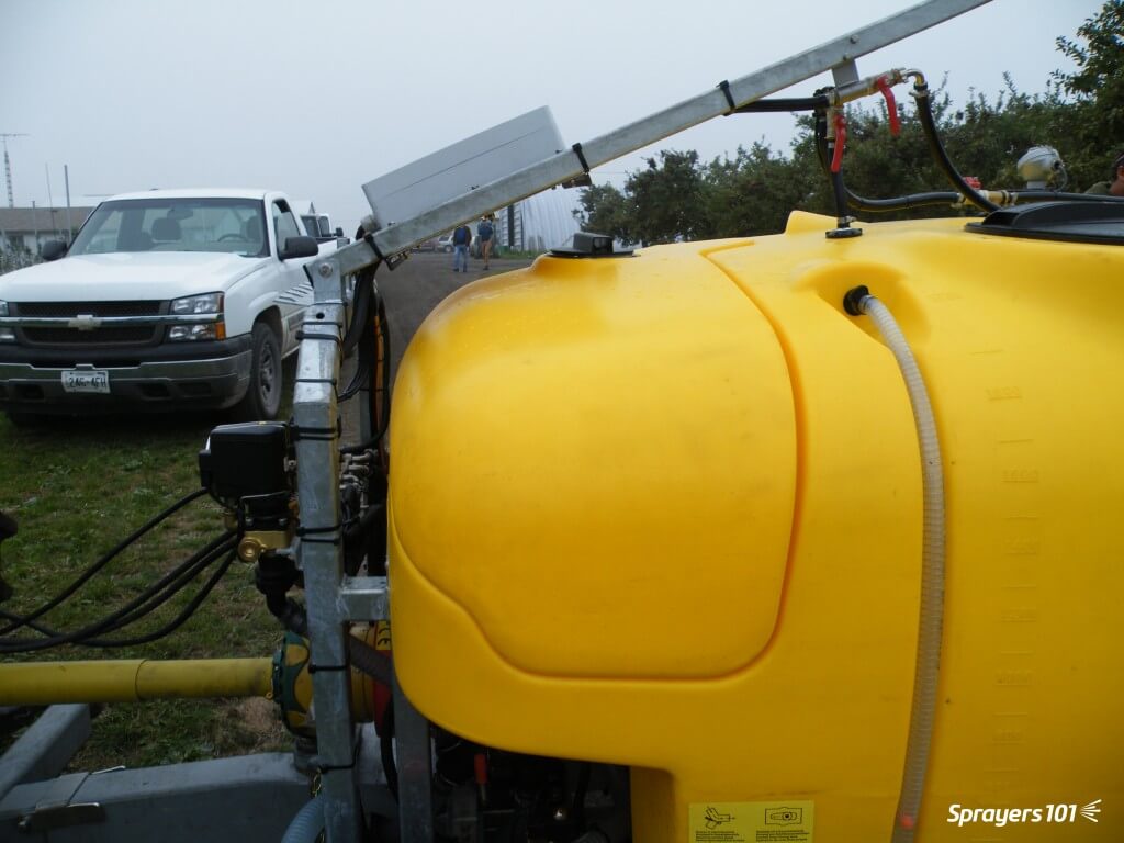
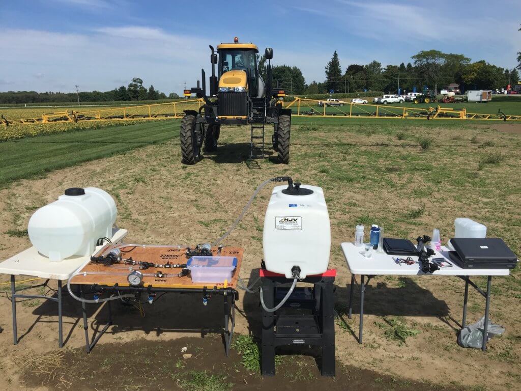
    Figure 1: Sprayer fill station

    At Sprayers101.com, we’ve tried to tackle the problem by finding ways to generate less waste (Express End Caps, Accu-Volume), by disposing of the rinsate by spraying it out, or by installing an efficient continuous rinsing system. We’d now like to talk about another component, biobeds.

    What is a biobed?

    Simply put, a biobed is a place where it’s safe and acceptable to dump dilute pesticide waste. First implemented in Sweden about 20 years ago, a biobed typically consists of a 1-m deep pit measuring about 3 m x 6 m or so. The pit is filled with a biomix, a mixture of cereal straw, compost or peat, and soil. The biomix, when properly prepared, acts to absorb a large amount of moisture, adsorb the pesticide molecules, and provide an environment in which microbes break down the residues.

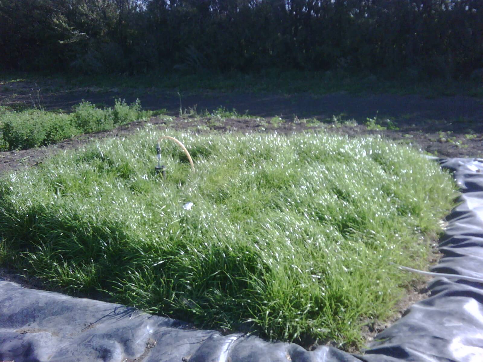
    Figure 2: Canada’s first commercial biobed installation at Indian Head, SK, 2009 (Source: Murray Belyk, Bayer CropScience (retired)).

    The effluent from a properly constructed biobed system contains 90 to 99% less pesticide than what was introduced, depending on the pesticide.

    Biobeds have been extensively studied and are now found throughout Europe and many parts of Central and South America. Canada currently has 6 research biobed sites in the West, and a further 17 in Quebec. The systems have been researched by Agriculture & Agri-Food Canada (AAFC) in recent years, with promising results.

    Figure 3: European biobed installations, 2016 (Source: Jens Husby, Biobeds.org).

    Figure 4: Global biobed installations, 2016 (Source: Jens Husby, Biobeds.org).

    Constructing a biobed

    There are many possible variations of biobeds, some relatively simple and others engineered to address certain specific needs. A great deal of creativity can be used to customize a biobed for any operation.

    A simple biobed

    The following is a variation of the simplest biobeds, and these are the types first tested by AAFC in Saskatoon and Indian Head, Saskatchewan about 10 years ago. This design is based on the biobeds established in Sweden and the UK, and is a good way to learn about the system.

    Note that this biobed has an impermeable liner, so it’s a closed system. Excess water that leaches to the bottom must be removed and cycled back to the top of the biobed.

    • Create the biomix by blending two parts, by volume, chopped cereal straw or wood chips (not cedar), one part mature plant-sourced compost or peat and one part relatively coarse-textured soil (for optimal drainage). Add water as necessary as if making compost. Allow to sit for four to six weeks.

    Figure 5: Biomix preparation.

    • During this waiting time, the biomix will warm and form a white-mold complex. This is the microbial basis for its ability to break down pesticide residues. White mold will be visible on the cellulose portions of the biomix.

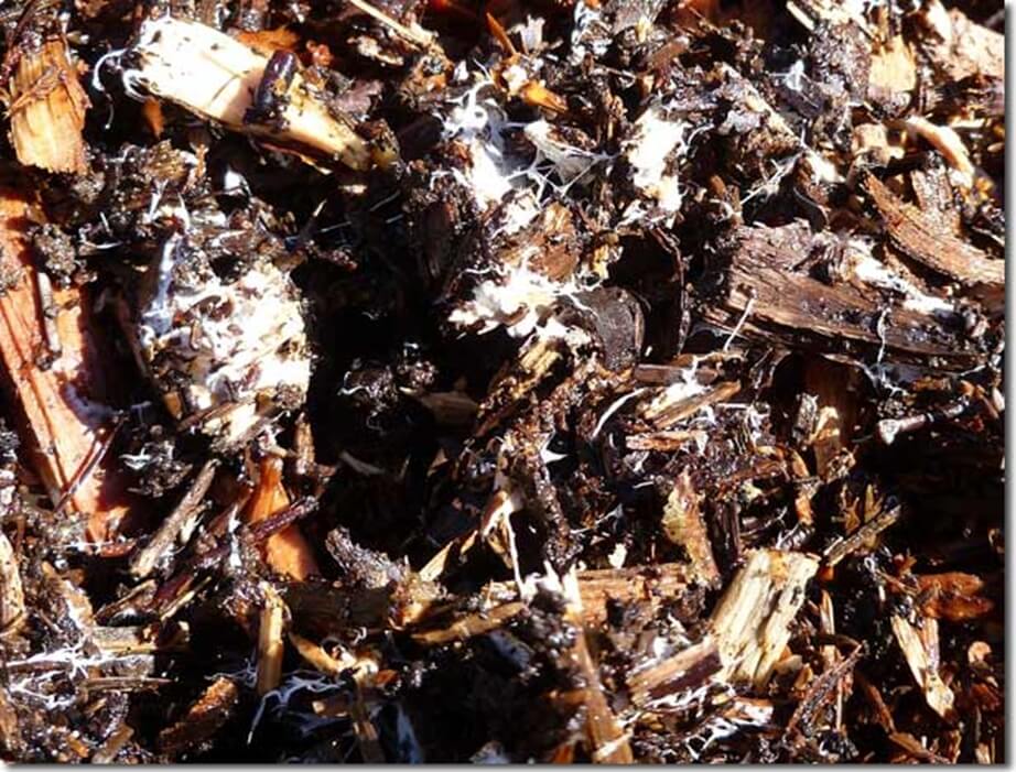
    Figure 6: white mold (Source: AAFC).

    • Identify a well-drained site easily accessible by spray equipment. Avoid low spots as water management becomes problematic.

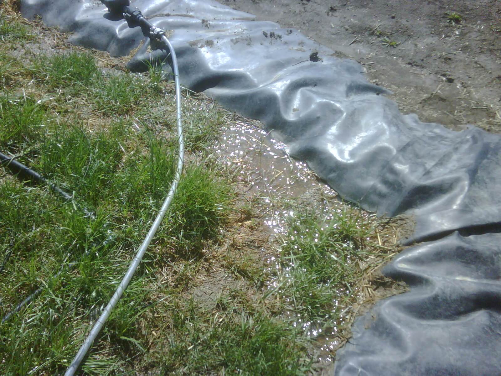
    Figure 7: Site selection and/or biobed covering are essential to avoid waterlogging (Source: Murray Belyk, Bayer CropScience (retired)).

    • Dig a pit sized to suit your requirements. As a rule of thumb, 1 m3 can process about 1000 L of liquid in a season. Rainfall is included in this amount.

    Figure 8: A nice looking pit.

    • Line the pit with a geomembrane liner. 40 mil is plenty thick; any thicker and it gets hard to handle. Include a raised berm at the edge.

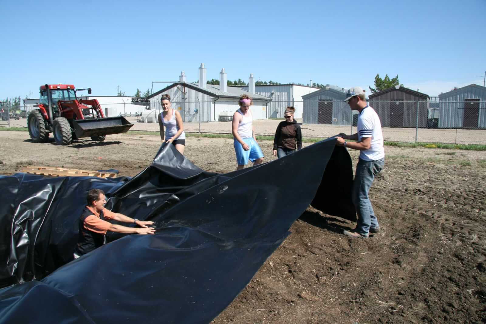
    Figure 9: Liner creates a closed system that will require a way to remove leached water.

    • Install weeping tile at bottom of pit, and extend it to ground level. This will be useful to determine water status and remove water if necessary.

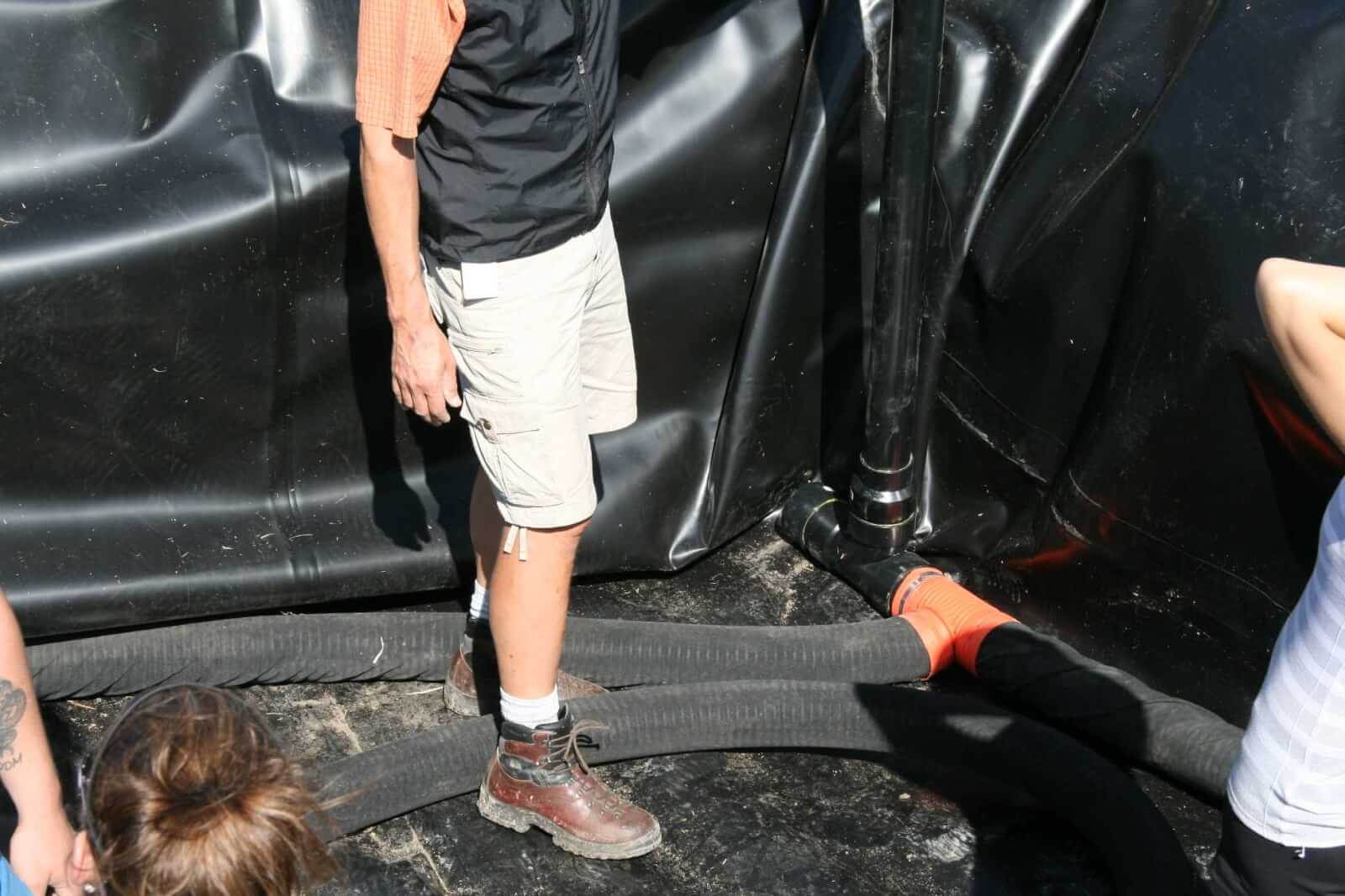
    Figure 10: Weeping tile to collect excess water.

    • Cover weeping tile with pea gravel and a silt trap. This serves to make leached water freely available for removal.

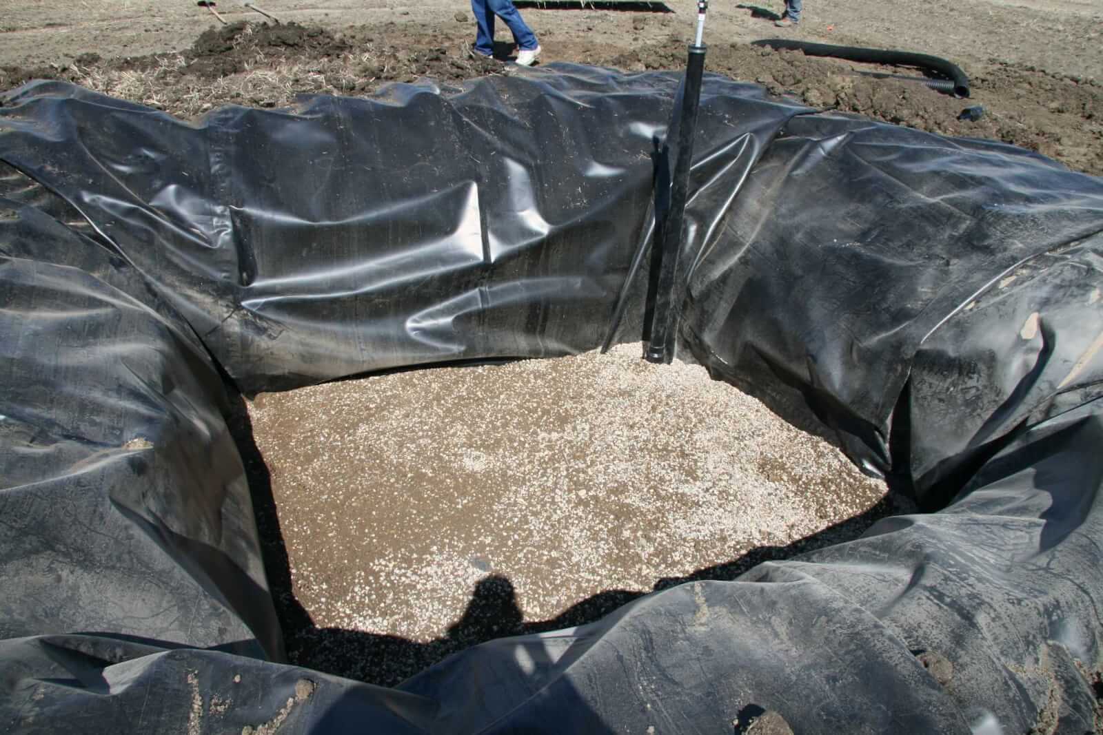
    Figure 11: Pea gravel over weeping tile.

    • Fill pit with biomix, anticipating significant settling. Top up as necessary over next few weeks. Use extra biomix to create a slope away from berm.

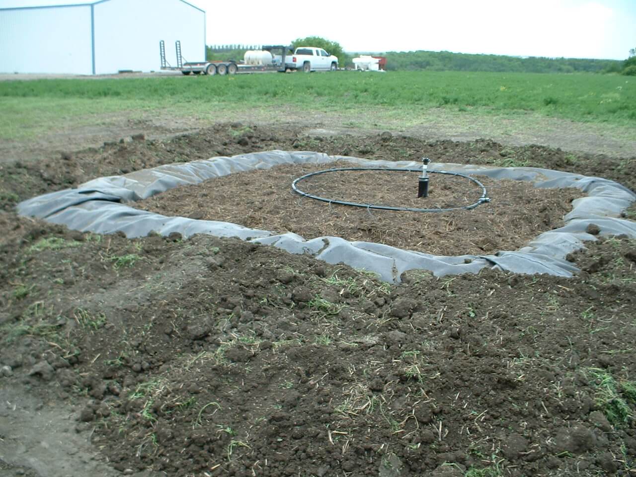
    Figure 12: Filled biobed.

    • Establish a bromegrass cover by transplanting or sodding. This is an important way to remove excess water via evapotranspiration.

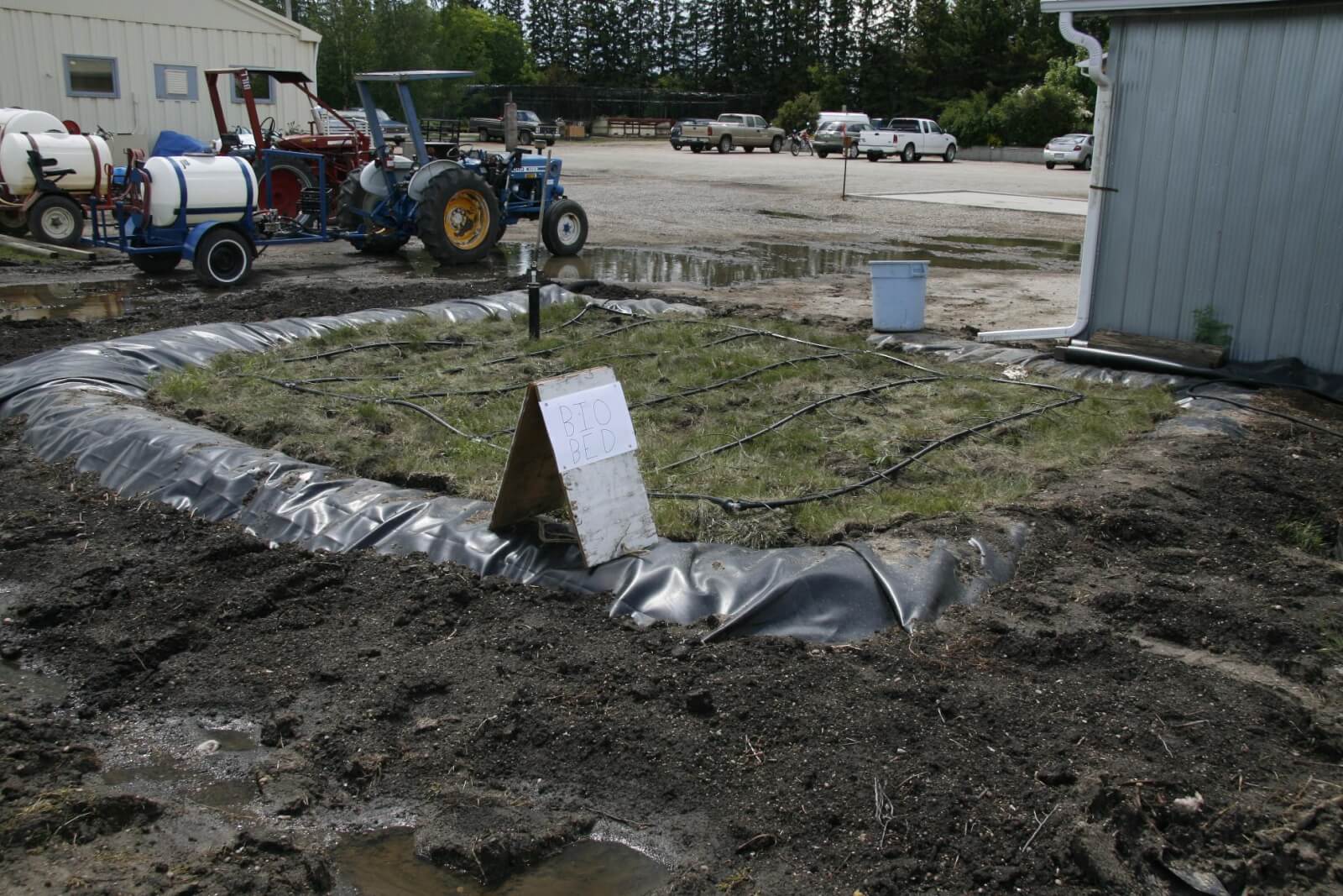
    Figure 13: Early sod growth on biobed at Indian Head, SK.

    • Introduce pesticide waste to biobed, managing moisture content to avoid waterlogging.

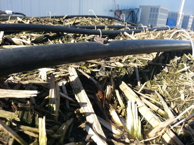
    Figure 14:  Pesticide waste entering biobed via drip irrigation.

    Introduction of pesticide waste to the biobed

    Moving pesticide waste from the sprayer to the biobed should be easy and trouble free. A simple pad built beside biobeds, either sealed with concrete or asphalt, or with a hardy geomembrane liner, works well. The sprayer is cleaned on this pad and rinsate flows into a drain. A sump pump lifts the rinsate to a storage tank from which it is introduced via gravity or pumped drip irrigation.

    Figure 15: Biobed system in Simpson, SK. Rinsate from sprayer is collected in a sump, which is pumped to the black storage tank in background. Rinsate is introduced into biobed (blue tub) as needed (Brian Caldwell in foreground, left, Larry Braul, right).

    When not in use, the sump drains freely to dispose of rain water.

    Others choose to pump or dump rinsate directly into a holding tank, from where it can be pumped onto the biobed.

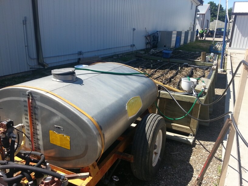
    Figure 16: Holding tank at biobed in Outlook, SK.

    Some European systems include driving supports on the biobed so the sprayer can be parked directly over top.

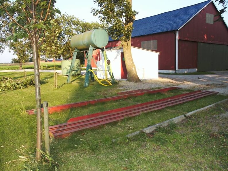
    Figure 17: Steel beams can allow (light) sprayer access (Source: Eskil Nilsson via Biobeds.org).

    A two-stage biobed

    The same basic building principles apply as in the original simple biobed. However, instead of reintroducing the effluent to the top of the biomix as it collects on the bottom, it is instead pumped onto a second biobed. This biobed then degrades any remaining product. This system is more efficient at degrading persistent products, and allows for better water management.

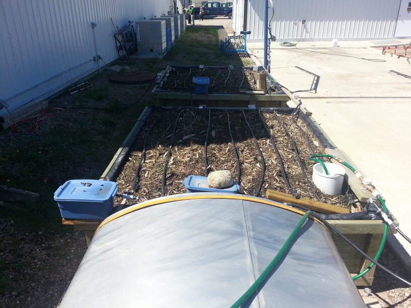
    Figure 18: Two-stage biobed system at Outlook, SK.

    The principle has proven effective, helping degrade more difficult pesticides to acceptable levels.

    Above-ground biobeds

    One of the problems with below-ground biobeds in wet climates is the difficulty managing water. Above-ground biobeds can address this issue by eliminating the possibility of surface runoff being added to the biomix. Adding a rain cover would also be easier and more effective.

    Above-ground biobeds can be edged with plywood, or placed entirely into plastic tanks whose tops have been removed.

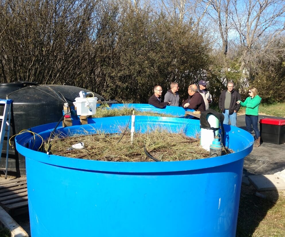
    Figure 19: Above ground biobed installation with plastic tub.

    One potential problem with above-ground biobeds is the later spring warming of this installation compared to below-ground types. Cold temperature reduces the effectiveness of biobeds due to the reliance on microbial activity. Heat tape has been tested by AAFC and shown to be very effective at warming the biomix and stimulating initial microbial activity. Passive solar systems have also been studied but are more difficult to install.

    Figure 20: Heat tape (Source: AAFC).

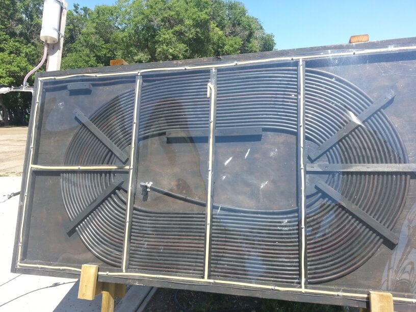
    Figure 21: Passive solar biomix heating system.

    Phytobac and Biofilters

    European designs have utilized plastic containers to form of various designs, including the commercial “Phytobac” systems from France and developed with the support of Bayer CropScience.

    Sequential biofilters have also been implemented. The leachate simply migrates through the biomix into the next container below. Eventually, adjacent biofilters containing plants act to remove the moisture.

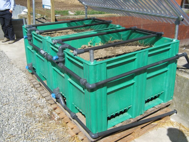
    Figure 22: Phytobac installation, cross-section.

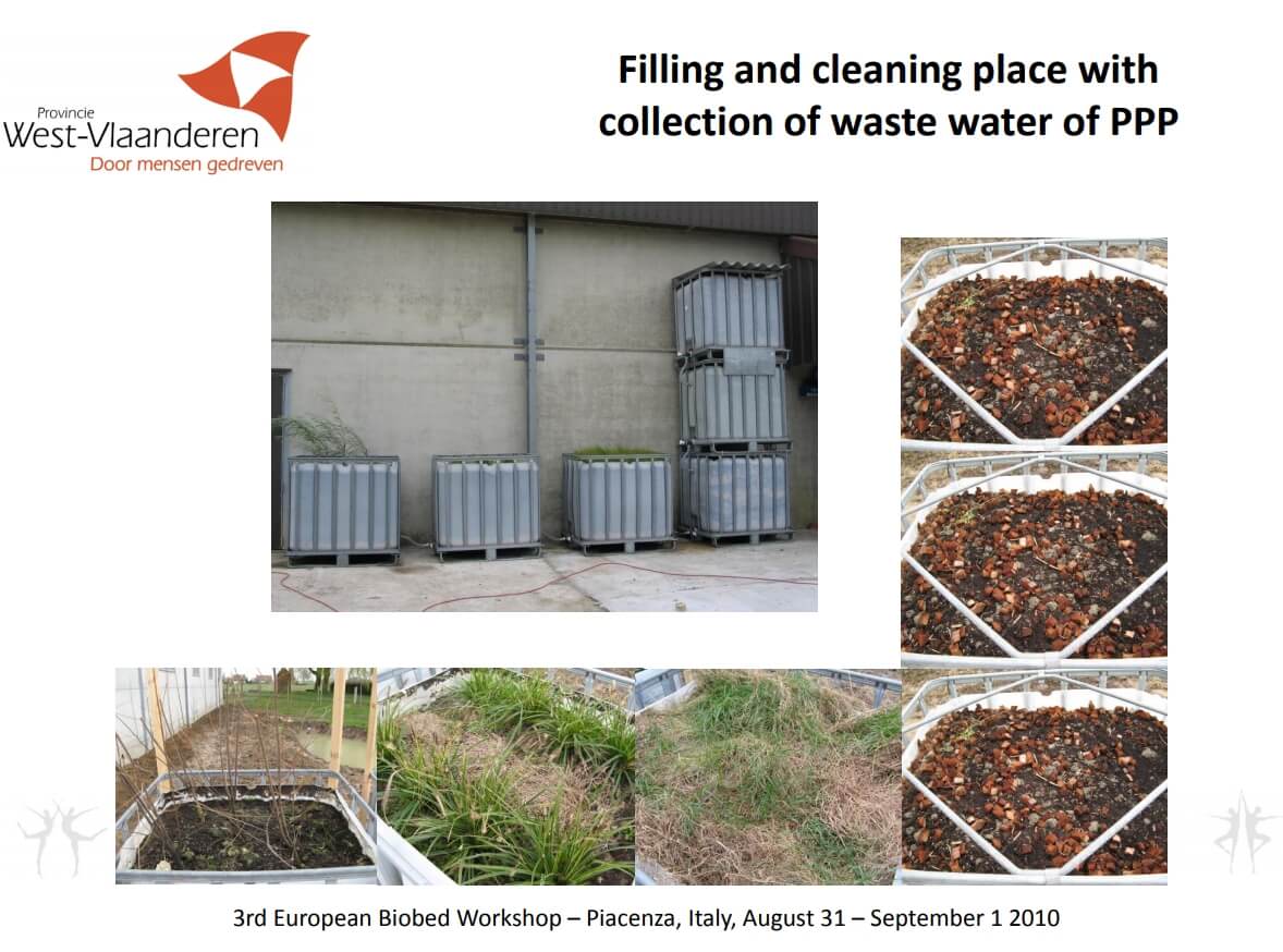
    Figure 23: Biofilter installation in Belgium (Source: Inge Mestdagh via Biobeds.org).

    Biomix longevity

    Swedish and UK research has suggested that biobeds require minimal maintenance aside from water management in closed systems. Biomix will settle over time and may need to be topped up. After five to eight years of use, it has been recommended to remove biomix and distribute it over a field with a manure spreader.

    Canadian research results

    Extensive analysis of pesticide degradation in five biobeds across Western Canada was conducted as part of a three-year study led by AAFC. Between eight and 51 products were analyzed per site, including herbicides, fungicides, and insecticides. Their results showed that single biobeds could remove about 90% of the introduced pesticide, and two in sequence usually removed more than 98%.

    Pesticides that tended not to degrade rapidly were removed to a greater degree in the second biobed.

    In the AAFC studies, three herbicides were more difficult to remove in the tested biobeds: clopyralid (e.g., Lontrel, Stinger), bentazon (Basagran, Storm) and imazethapyr (Pursuit, Arsenal). For these three, roughly 60% was removed in a two-biobed system.

    Concentrated pesticides should not be introduced to a biobed as this will kill the microbial populations.

    Some fungicides were shown to depress microbial populations but only temporarily. Microbial breakdown still occurred.

    Biobed manual

    AAFC has authored a comprehensive manual on biobed operation and installation based on research experience in Canada and elsewhere. It will be available here in late June 2018.

    The future of biobeds

    Research into biobeds remains active around the world. Different substrates for the biomix are being studied to suit local availabilities. Various systems, ranging from simple to highly engineered are being studied. Degradation effectiveness for various influents remains a topic of significant interest. Producer adoption and implementation are being reported.

    Thanks to funded research projects, biobeds are up and working at Canadian institutional sites such as government research centres, and there are opportunities for county and municipal government sites. For biobeds to be a viable option on North American farms, their design needs to remain simple and their integration into established practices needs to be seamless. Producer experience and feedback are essential

    Learn more

    Valuable information on biobeds can be obtained from these two websites:

    Voluntary Initiative (UK industry)

    Biobeds.org (International research)

    Note: Brian Caldwell and I first learned about biobeds from Eskil Nilsson (website) during a visit to Sweden in 2001, and obtained support for initial studies in Saskatoon and Indian Head from the Pest Management Centre as well as Bayer CropScience. Brian took a lead in our creative and technical efforts over many years. Dean Ngombe, under the co-supervision of Diane Knight at the U of S and myself, produced the first M.Sc. thesis, and with significant input from Allan Cessna, the first scientific publications in Canada on biobeds. Thanks for Larry Braul and many collaborators for leading the most recent AAFC study and generously sharing resources, and Erl Svendsen, Bruce Gossen, and Claudia Sheedy for editorial input.

  • Diluting 20,000-Fold with a 30 Gallon Remaining Volume in a 1,200 Gallon Tank

    Diluting 20,000-Fold with a 30 Gallon Remaining Volume in a 1,200 Gallon Tank

    (This short article is an addendum to this article)

    Our goal in this example is to dilute by a factor of 20,000.

    The maximum amount of dilution possible with a 1,200 gallon tank and a 30 gallon remainder is 1200/30=40.

    The formulae:

    Dilution per Rinse = final dilution ^(1/# of rinses)

    Rinse Volume = (dilution per rinse * remaining volume) – remaining volume

    • One rinse diluting by 20,000 – impossible with a 1,200 gallon tank (max achievable is 40-fold);
    • Two sequential rinses, each diluting by a factor of 20,000^(1/2) = 141. Also impossible with a 1,200 gallon tank;
    • Three sequential rinses, each diluting by a factor of 20,000^(1/3) = 27. A volume of 780 gallons can do this  (27*30)-30=780 gallons. For three rinses, the total volume is 2,340 gallons.
    • Four sequential rinses, each diluting by a factor of 20,000^(1/4) = 12. A volume of 330 gallons can do this, for a total volume of 1,320 gallons;
    • Five sequential rinses, each diluting by a factor of 20,000^(1/5) = 7. A volume of 180 gallons can do this, for a total volume of 900 gallons;
    • Six sequential rinses, each diluting by a factor of 20,000^(1/6) = 5.2. A volume of 126 gallons can do this, for a total volume of 757 gallons.

    Second, let’s assume the operator is prepared to prime the boom where it doesn’t harm soybeans. Now the first new product tank takes care of the last dilution, lowering the cleanout dilution requirement by 1,200/30 = a factor of 40. Now the cleanout dilution requirement is only 20,000/40 = 500.

    • One 1,200 gallon tank rinse can only achieve 40-fold dilution.
    • Two rinses, each diluting by 500^(1/2) = 22. Rinse volumes of 640 gallons are sufficient, for a total of 1,280 gallons.
    • Three sequential rinses, each diluting by a factor of 500^(1/3) = 7.9. A volume of 210 gallons can do this, for a total volume of 630 gallons;
    • Four sequential rinses, each diluting by a factor of 500^(1/4) = 4.7. A volume of 112 gallons can do this, for a total volume of 448 gallons.
  • How Clean is Clean?

    How Clean is Clean?

    One of the more perplexing questions in tank cleanout is knowing when the cleaning process is good enough to prevent harm. This question is especially relevant to producers that grow canola and use Group 2 herbicide products, or grow soybeans and use dicamba on some of their area. In both of these examples, crops can be extremely sensitive to very small residues.

    When does an applicator know that the cleaning job was good enough? In about two weeks! There is no easy way to tell, except to be precautionary.

    A bit of math can help put us in the ballpark. First, we need to know the tolerance of a crop to the herbicide, preferably expressed as a proportion of the tank mix to be cleaned. Let’s use dicamba as an example. It’s been reported that non-dicamba tolerant soybeans can show leaf-cupping symptoms from dicamba at rates as low as 1/20,000 of the label rate.

    Recall that sprayer cleanout is really two separate processes that we’ve written about here, here, and here. The first is dilution of the remaining volume in the system. The second is decontaminating specific sprayer components (filters, boom ends, hoses). We’ll focus on dilution in this article.

    If you’re diluting, the second piece of information you need is how much liquid is left in the sprayer when you start cleaning. All sprayers have a certain amount of liquid left in the tank and associated plumbing after the tank is empty. The sump, the suction line feeding the pump, and the lines returning to the tank via agitation or sparge are most common. Even when the pump no longer draws liquid, those lines retain some volume of product. This volume can’t be pushed out to the boom, most of it goes back to the tank.

    The volume of this “remaining liquid” is likely somewhere between three and thirty US gallons.

    The remainder volume depends on the sprayer, and also how the tank is emptied. Some applicators simply spray until the solution pump pressure drops, others choose to drain the remaining liquid from a sump valve. When draining, product should be captured in pails rather than allowing it on the ground where it will harm the soil and possibly make its way into runoff.

    It’s always preferable to spray the tank empty in a field.

    As we’ll see below, a low remaining volume greatly improves the efficiency of the dilution process. It’s a sprayer feature that should be considered at purchase.

    The table below has some sample calculations. Note that the paired cases (1&2, 3&4, 6&7) all use the same total water volume, but compare a single vs triple rinse of three different remaining volumes.

    Comparing Case 1 to Case 3 or Case 6, (remaining volumes of 10, 20, and 50, respectively), it’s clear that minimizing the remaining volume is important.

    It’s also striking that the same amount of clean water, subdivided into three smaller repeat batches (Case 2, 4 and 7), is much more powerful than using single batches with the same total clean water amounts.

    Reducing the size of each batch even further and increasing the number of batches (Case 5) approaches what a properly executed continuous rinse can do.

    Is it necessary to dilute to the level that’s safe for the next crop? Not always. The next product in the tank acts to dilute the remainder once again, possibly by a factor of 100, depending on the remaining volume and the tank size (Case 8). The material in the boom, however, won’t be diluted by this additional volume, and therefore may harm the crop unless it is first sprayed out elsewhere, especially when section ends are not drained and rinsed.

    This is where a recirculating boom is valuable, providing an opportunity to charge the boom without spraying. The penalty is that the boom volume is then returned to the tank in the process, increasing the amount that needs to be diluted.

    Let’s return to the dicamba example with a 20,000-fold dilution requirement and a 1,200 gallon tank. We’ll consider two examples. In the first, the operator wants to prime the boom in the soybean field without any harm to the dicamba-susceptible beans. A 20,000-fold dilution is needed.

    We’ve looked at five options that each assume a remaining volume of 10 gallons. Note that our goal is the same – dilute by a factor of 20,000.

    The formulae:

    Dilution per Rinse = final dilution ^(1/# of rinses)

    Rinse Volume = (dilution per rinse * remaining volume) – remaining volume

    The maximum amount of dilution possible with a 1,200 gallon tank and a 10 gallon remainder is 120 (see Row 8, Table above).

    • One rinse diluting by 20,000 – impossible with a 1,200 gallon tank (max achievable is 120-fold);
    • Two sequential rinses each diluting by a factor of 20,000^(1/2) = 141. Also impossible with a 1,200 gallon tank;
    • Three sequential rinses, each diluting by a factor of 20,000^(1/3) = 27. A volume of 260 gallons can do this  (27*10)-10=260 gallons. For three rinses, the total volume is 780 gallons.
    • Four sequential rinses, each diluting by a factor of 20,000^(1/4) = 12. A volume of 110 gallons can do this, for a total volume of 440 gallons;
    • Five sequential rinses, each diluting by a factor of 20,000^(1/5) = 7. A volume of 60 gallons can do this, for a total volume of 300 gallons.

    The first two examples don’t work because the tank isn’t big enough. But the three remaining examples all work equally well, they just consume different amounts of clean water.

    If that doesn’t seem like a lot of work, then repeat this calculation with a 30 gallon remainder volume, common on many sprayers. Short on time? We did it for you here.

    Second, let’s assume the operator is prepared to prime the boom where it doesn’t harm soybeans. Now the first new product tank takes care of the last dilution, lowering the cleanout dilution requirement by 1,200/10 = a factor of 120. Now the cleanout dilution requirement is only 20,000/120 = 166.

    • One 1,200 gallon tank rinse can only achieve 120-fold dilution.
    • Two rinses, each diluting by 166^(1/2) = 13. Rinse volumes of 120 gallons are sufficient, for a total of 240 gallons.
    • Three sequential rinses, each diluting by a factor of 166^(1/3) = 6. A volume of 50 gallons can do this, for a total volume of 150 gallons.

    The math is simple, and can be done using the formula in the first table, or this app:

    The hard part is knowing what the remaining volume is. It would be very useful for a manufacturer to provide this information.

    In the meantime, you can estimate on your own. Add water with surfactant to your tank, and spray it empty. While spraying, turn the agitation on and off to fill and activate the sparge, if equipped. Once the tank is empty and the spray pressure drops, stop and drain the sump into pails. Ensure that the pump suction line and the pressure line up to and including the agitation and sparge lines also drain. Disconnect these if necessary. If there is a filter housing in this circuit, remove it as well.  Avoid collecting liquid from the pressure line beyond where the the agitation or sparge split off, as this will be pushed out to the boom.

    An alternative is to estimate the length of hose in this circuit, using the following table as a guide:

    And remember, diluting the remaining liquid is only one part of a cleaning process.