When operators winterize their sprayers, they should remove all the tips and store them separately. Many store them in large pails with lids. Calibrating the sprayer just prior to winterizing will indicate if the nozzles should be stored, or replaced. Let’s assume each tip flow rate is within 5% of the average output and no more than 5% more than the manufacturer’s pressure tables. Yes, industry standard is 10%, but I always wonder how the spray quality suffers with that much wear. Nozzles are, comparatively, a cheap replacement and it’s not worth skimping. Learn more how to check nozzle flow rate, here.
Just like any other part of the sprayer that comes in contact with spray liquid, nozzles (and strainers) should be cleaned regularly. And, just like any other part of the plumbing, the best way to do that is to dilute any residues via a series of rinses. For a more rigorous cleaning, one of the intermediate rinses should include a detergent, and soaking during this step is an excellent practice.
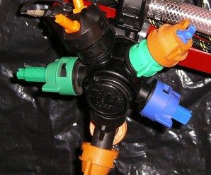
The orifice of any nozzle is delicate, either machined or molded to exacting standards. Even small changes to the orifice shape results in distorted spray (e.g. spray comes out at undesirable angles), a change to the rate (typically more volume per minute) and a change in the spray quality (typically larger median droplet size). If foreign objects or residues remain in the tips, the subsequent spray job may be less accurate and even damage the tips.
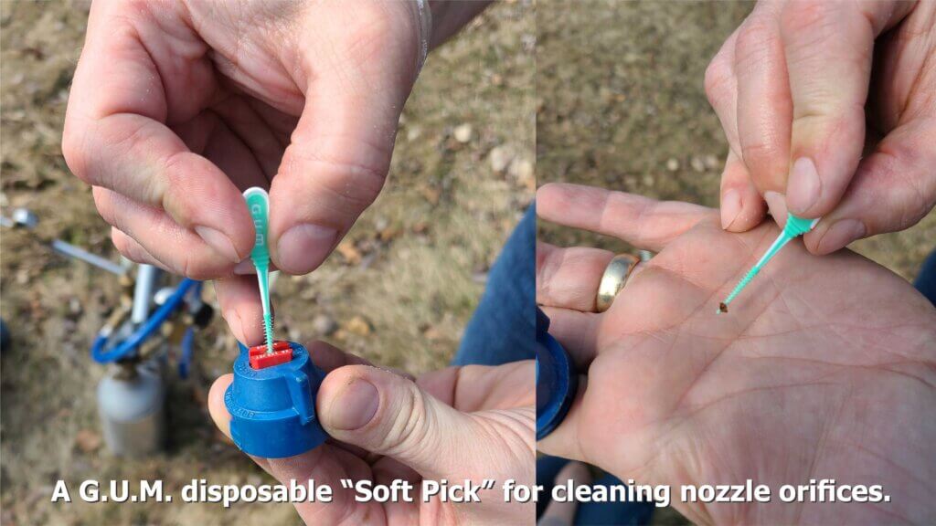
In the case of air induction nozzles, which are essentially the standard on most boom sprayers, debris and weed seeds can plug the air-intake ports. When that happens, the nozzle will not function as intended. So, while the occasional soaking of nozzles does a great deal of good, they may also have to be scrubbed. Don’t use picks or reamers! There are nozzle cleaning tools out there, but they’re basically toothbrushes so save your old ones (and mark them clearly). Soft bristles are the way to go for removing stubborn residues and cleaning any tip orifices, but we found a nifty new way:
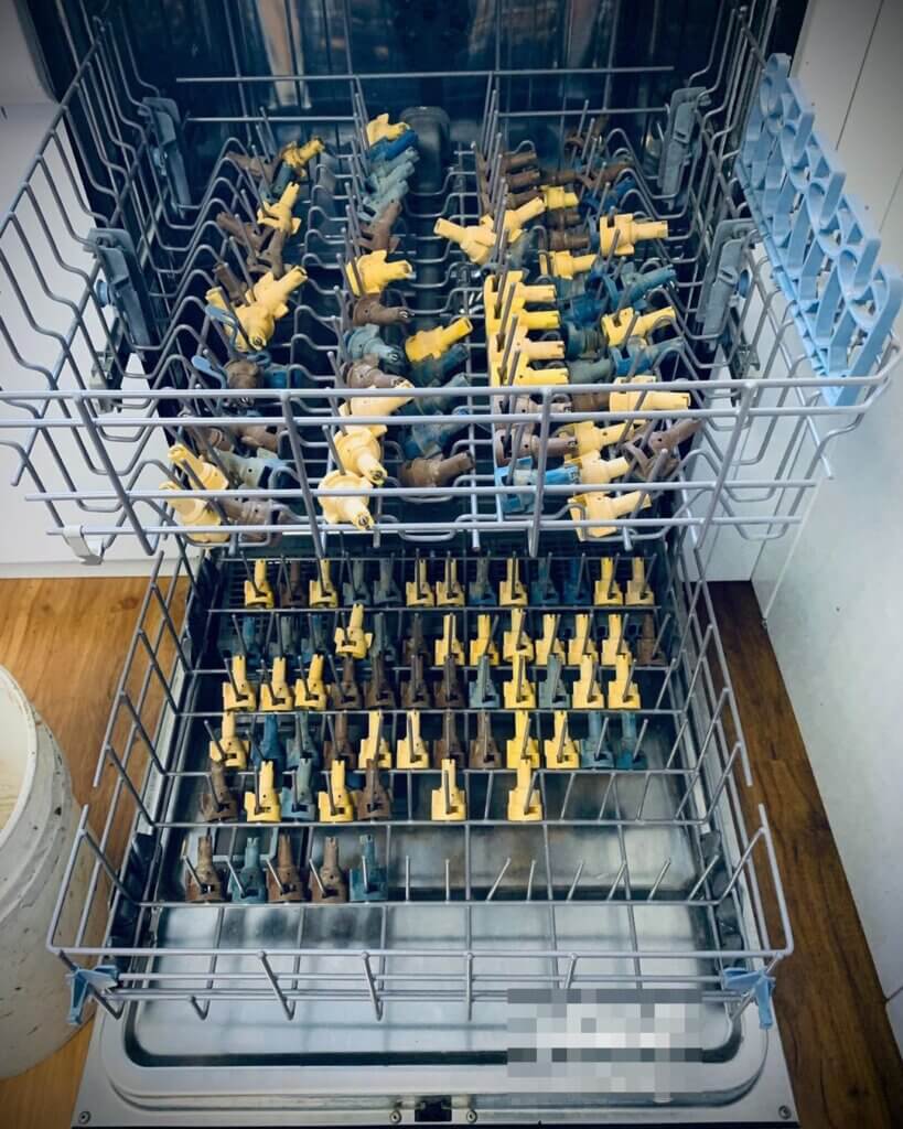
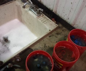
Occasionally we receive photos like the one below and we’re asked what we think. Well, just the same way we don’t recommend cleaning your sprayer overalls in the family clothes washer, we also don’t recommend the use of dishwashers for nozzles.
Not a great idea. Certainly not if you intend to ever use this dishwasher for anything else. And where does the rinsate go?
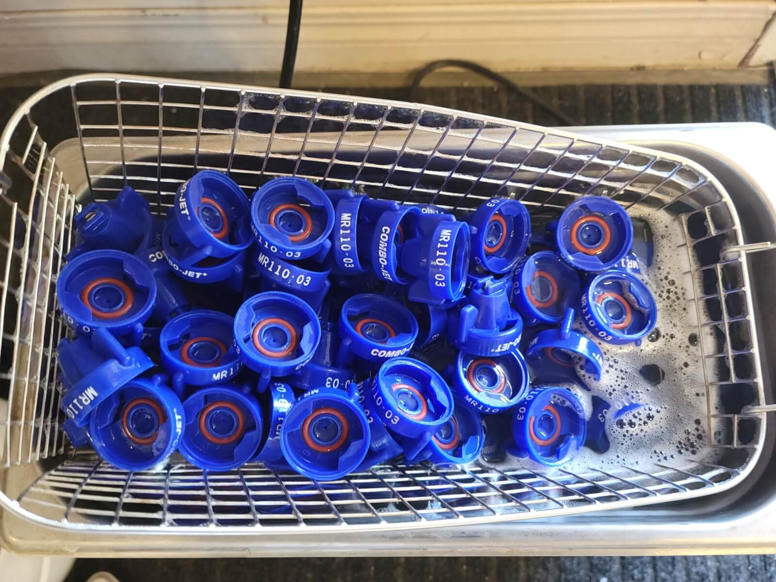
In an interesting experiment, Lucas Olenick of Wilger tried cleaning tips in a heated ultrasonic cleaner. We haven’t tested this and we don’t know what heat and vibration might do to poly and ceramic components, but surely it’s no more aggressive than hot, soapy water and a bristle brush. Lucas tried several durations with and without detergent and arrived at this recipe:
“For tough, non-water-soluble pesticides, around 8+ hours in a heated ultra-sonic cleaner with (Dawn) dish soap to come out like brand new. Other solvents may speed this up, but I’d generally suggest against heating solvents at any concentration. For water-soluble pesticides, expect to be within the 3-6+ hours for the first time to be confident enough in not having to flow-test each of the nozzles. With any pesticides, ensure proper care in handling contaminated nozzles and rinsate after cleaning nozzles.”
The mad genius of Lucas Olenick (@WilgerParts) who used dish detergent and a heated sonic cleaner to unplug tips. Be sure to dispose of rinsate safely. Photo credit: Lucas Olenick.
Don’t have a heated sonic cleaner? No problem. Here’s a step by step:
Wearing gloves, remove all nozzles, strainers, rubber gaskets and tips from the sprayer.
Put them in a large plastic pail and cover them in warm water. Leave them to soak.
Drain the pail, but be aware that the rinsate will have pesticide residue.
Fill a second pail with a solution of the same commercial detergent used to clean the sprayer.
With a toothbrush, scrub the caps, gaskets, strainers and nozzles to remove any residue. Some nozzles can be pulled apart to expose the mixing chamber and facilitate cleaning.
Once scrubbed, leave all the parts to soak in the detergent solution.
Drain the solution, which will contain trace amounts of pesticide, rinse the parts with water and reassemble the nozzles.
While you’re at it, drop those filters and scrub them alongside the tips. This may seem extreme, but of all the technology on a sprayer, the nozzle has the biggest impact on the effectiveness and efficiency of the spray job. Take the opportunity over the winter months to clean and inspect the tips for damage so the sprayer is ready for calibration in the spring.
Soak, scrub, rinse and store nozzles and nozzle strainers. You may replace them once the sprayer is clean, but I prefer to store then separately. Photo credit: Jason Boersma (@RVFBoys), Ridge Valley Farms, Ontario.
Thanks to Jason Boersma (@RVFBoys), Ridge Valley Farms, Ontario, who sparked this article with his tweet: “Great job for a cold winter day, soak & clean all your tips to be ready for spring also saves on down time!”
Cleaning, flushing, triple-rinsing… whatever you call it, sprayer sanitation is a time-consuming and distasteful task.
Methods vary, but they generally span from the classic triple rinse (30-45 minutes) to a full tear-down and decontamination (many hours and likely an overnight soak). The operator decides how much time and effort to invest depending on the chemistry they’ve just used and the crop they intend to spray next. Learn more about the power of dilution in this article and in this article.
Unfortunately, two facts are certain:
At minimum, operators should rinse the sprayer at the end of each day… and they generally don’t.
It is only after spraying a sensitive crop that the operator truly knows whether the sprayer was cleaned sufficiently.
Continuous Rinsing
We’ve promoted Continuous Rinsing as a viable alternative to Triple Rinsing in previous articles (see here and here). Executed correctly, the method:
greatly reduces the time required,
is as effective,
eliminates operator exposure, and
reduces potential environmental contamination.
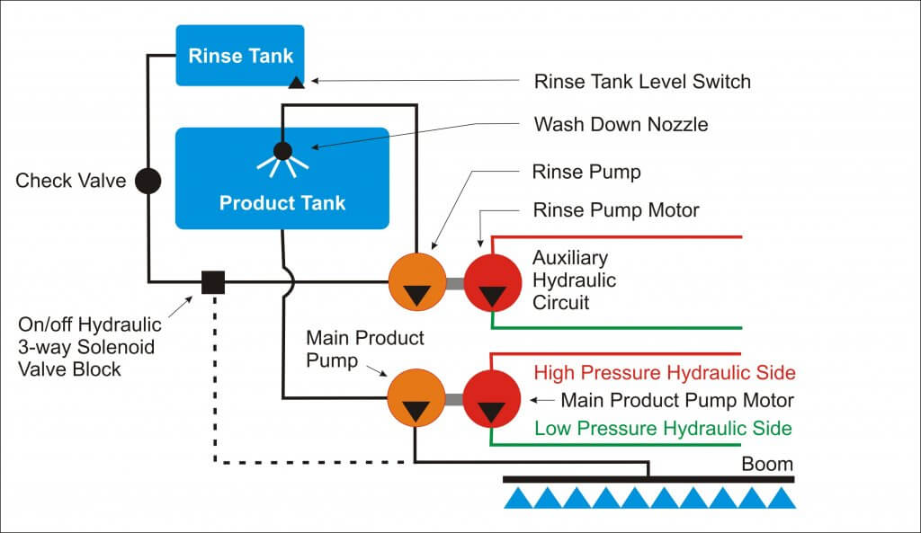
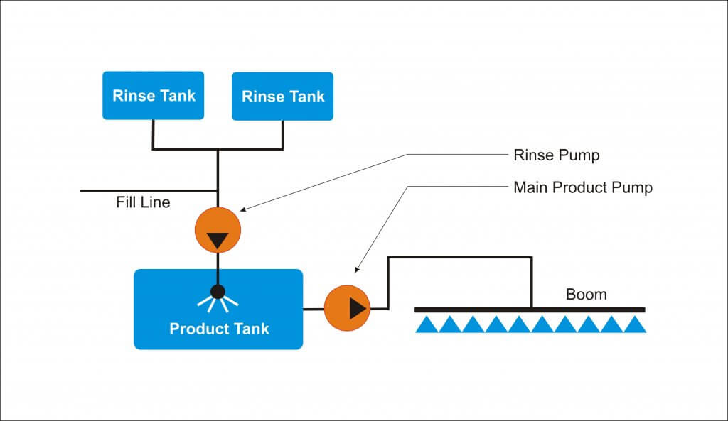
Continuous rinsing requires the installation of a dedicated “rinse pump” to transfer clean water to the product tank from the rinse tank via the wash-down nozzles. This permits the main product pump to operate simultaneously, emptying the product tank and spraying the rinsate out the boom.
Imagine your sprayer empties at the end of the row. You position the sprayer at a headland or a row you sprayed earlier. A toggle switch in the cab engages the rinse pump and the wash-down nozzles start spraying clean water into the product tank. You then resume driving and spray until the rinse tank is empty. During the process, any solution in the return/bypass line is quickly diluted, and any standing volume in the system is displaced by clean water.
It takes five minutes and you never left the cab.
Remember: Rinsing can dilute residue to ~2-5% in most of the sprayer plumbing, but it is not intended to replace the more rigorous decontamination process. Closed circuits, filters and dead-end plumbing can still harbour residue >15%.
Installation
Working with GreenLea Ag Center in 2017, we installed a Continuous Rinse system on a Case IH Patriot 4440. It has a 1,200 gal. product tank, a 140 gal. rinse tank and a 120 foot boom. A parts/price list for the Patriot installation appears at the end of this article.
Additionally, we have included the parts/price list from our 2016 HJV Equipment installation on a RoGator 700, which had a 700 gal. product tank, 50 gal. rinse tank and a 90 foot boom.
Still further, we have included three homegrown solutions from operators that developed their own continuous rinse systems.
Sizing the Rinse Pump
It is very important that the rinse pump has the capacity to operate the wash-down nozzles and still supply clean water at a rate approximately equal to the rate at the boom. Basically, “in must equal out”. If the rinse pump supplies too much clean water, the volume rises in the product tank and efficiency is reduced. If it cannot supply enough, the main product pump will lose suction and not function correctly.
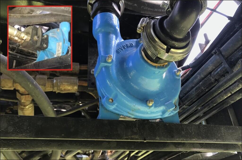
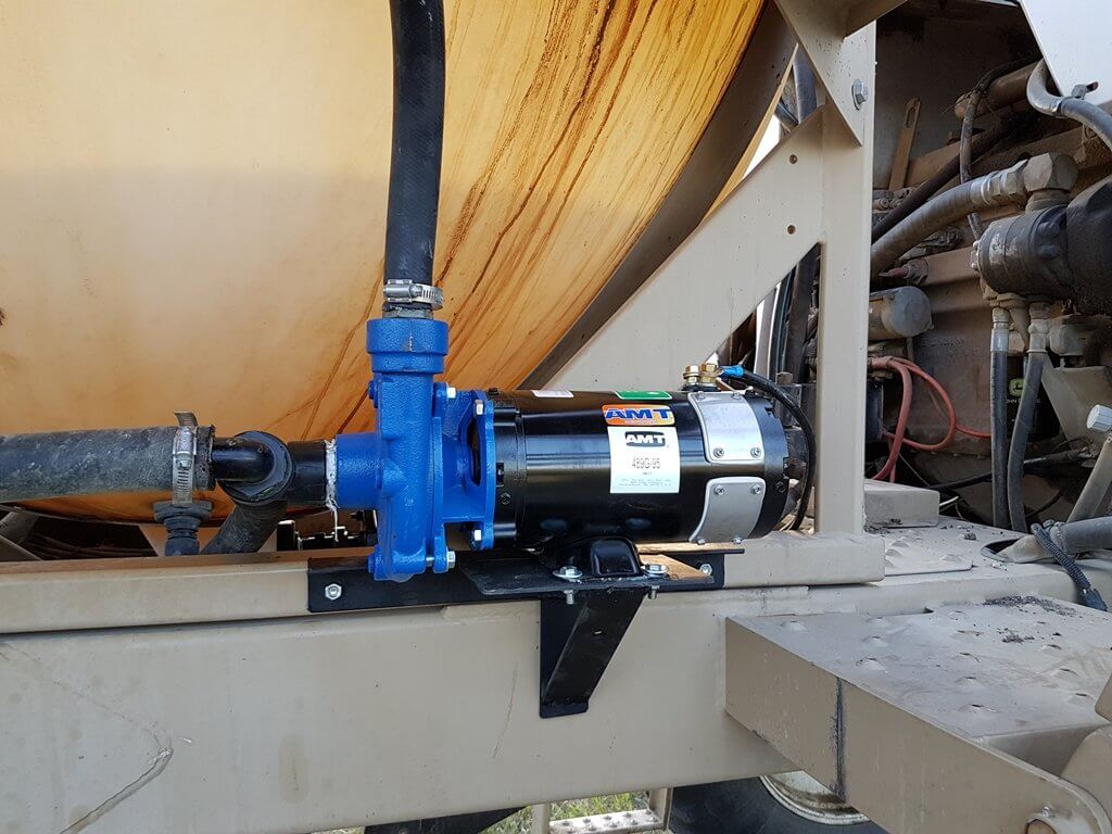
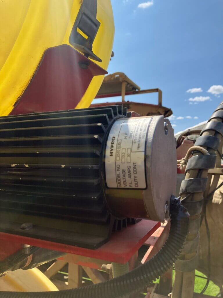
We installed a Hypro 9303C-HM1C centrifugal pump (max flow rate of 114 gpm at 130 psi), matching the make and model of the exiting product pump. A length of channel was installed on the chassis to mount the pump and close-coupled hydraulic rinse pump motor, and a valve block.
Really, electric pump installation is easiest. An alternate pump that has been used is this one from Pattison Liquid. For added benefit, it’s a chem transfer pump that can handle the pesticide formulations. If the pump doesn’t give enough flow, a second one can be installed parallel to double the flow.
Hydraulics
Let’s being with advising caution: If you are uncertain about your hydraulic capacity (and tightly designed systems rarely have extra) then consult with a manufacturer-certified service technician, or consider an electrical alternative.
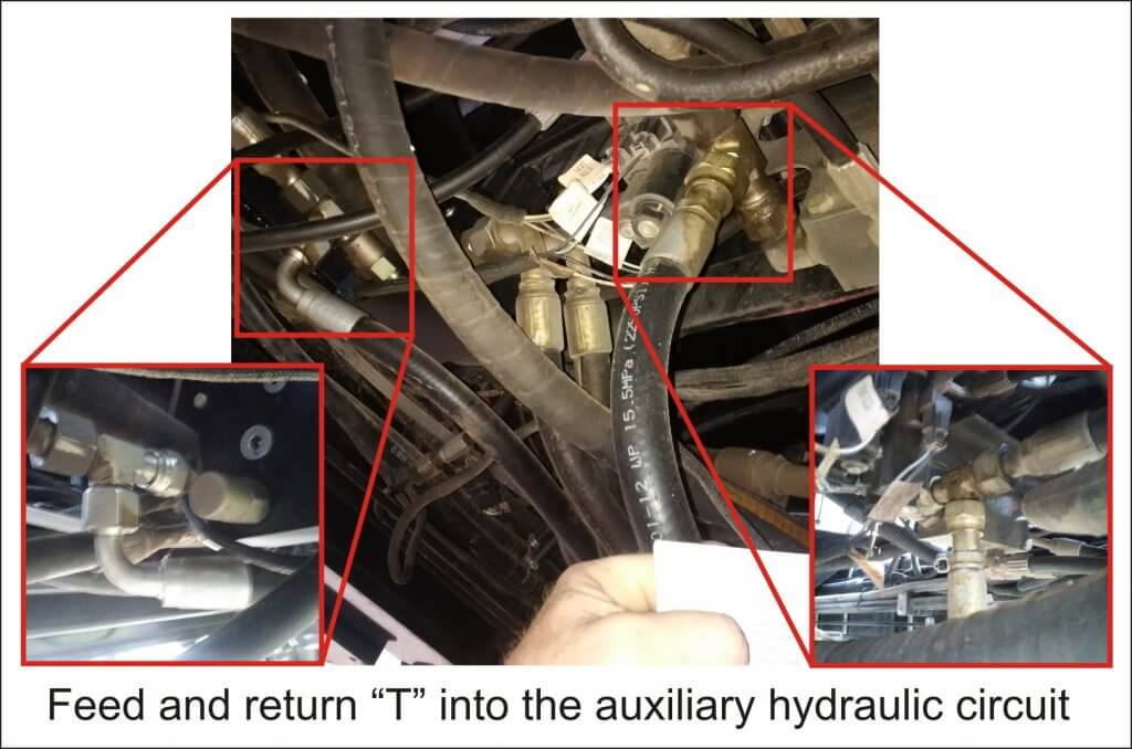
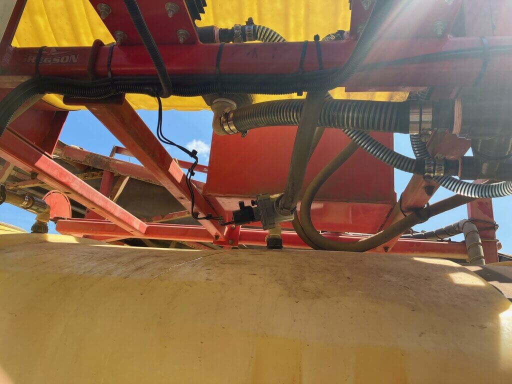
For the Patriot, the auxiliary hydraulic circuit was used to drive the hydraulic rinse pump; we piggy-backed off of that existing system. In this case, Continuous Rinsing increased the load on the auxiliary hydraulic circuit, but only marginally, so performance was acceptable.
We drew that hydraulic flow directly from the auxiliary pump output using a ‘T’ piece to ensure full pressure was available when needed. Then we broke into a common low pressure return manifold using another ‘T’ piece to provide the return flow.
Originally, we were concerned that robbing too much hydraulic flow could compromise sprayer operations. We therefore exchanged the hydraulic motor that came with the pump for one that required less hydraulic flow. However, the pump operated at such a high speed that the rinse tank was drained in two minutes! We felt this would not give the operator enough time to make minor adjustments (see the “Avoid Airlock” section later in the article). We also felt the rinsate would not have enough time to hyrdate any residue in the tank and lines. We therefore returned to the motor that came with the pump, slowing the pump and bringing our rinse time to approximately five minutes.
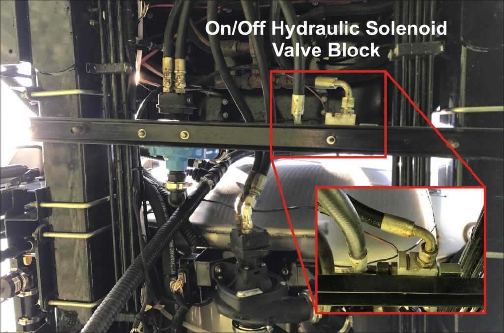
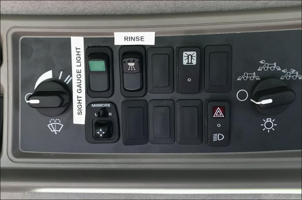
We installed an on/off hydraulic control valve block and solenoid controlled by a toggle switch in the cab. When the rinse switch was engaged, 12 volt DC opened the solenoid, allowing hydraulic oil from the auxiliary pump to turn the rinse motor, which in turn powered the rinse product pump.
Avoid Airlock by Balancing Flow
While Continuous Rinsing works well with an unbroken stream of clean water, there is demonstrated benefit to allowing the pump to draw a small amount of air. The bubbles are reputed to scrub the lines more effectively than water alone. It is possible that the new Hypro 9307 series centrifugal pump, which claims to eliminate dry run, would facilitate this.
However, avoid excessive cavitation or airlock of the main product pump. This will damage the pump seals and interfere with pump suction. If the main product pump is a piston-diaphragm pump, avoid losing the prime by letting a small volume of rinse water build up in the product tank before spraying the rinsate.
Maintaining the balance between the supply from the rinse pump, and demand by the product pump, will take careful trial and error. If the sprayer employs a rate controller, speeding up or slowing down travel speed is a means for making adjustments to match the two flows. Alternately, an operator can adjust the pressure regulator manually. Remember, the nozzles won’t need to work optimally so you have the option to use fairly low pressures to match flows.
In the case of an operator applying 28-0-0 using dribble bars or fertilizer nozzles, there is likely too much flow at the boom for the rinse pump to keep up. While we have not tried it, but as long as there was sufficient volume in the clean water tank, it might be possible to rinse the boom section by section, starting with the outside sections and moving in towards the centre.
Lessons Learned
The installation was a learning process, during which we noted the following:
At first, the rinse tank slowly emptied through the rinse pump, even when it wasn’t in use. We prevented this by installing a 10 psi check valve between the pump and main tank.
The rinse pump ran dry and burned the seals when the operator forgot to turn it off after the rinse tank was empty. We considered a timer or alarms to prevent this, but chose to install a level sensor (essentially a float) which would cut the 12 Volt DC feed to the on /off solenoid, effectively turning the system off when the rinse tank was empty. Note: the sensor is not in the parts list – it was purchased for ~$10.00 CAD from Amazon.
When deciding where to draw hydraulic flow to run the rinse pump, we first tied into the main hydraulic circuit (i.e. not the auxiliary). This negatively affected both steering and boom control. Beware drawing flow from critical safety systems such as steering.
Future Development and Other Advantages
GreenLea was exploring an option to use the rinse pump to bypass the product tank, and flow directly to the boom. This can be accomplished by teeing an electrical 3-way ball valve just after the pump to allow flow directly from the rinse tank (see dashed line in the flow schematic shown earlier in the article). Imagine being rained out, or having excess mix left in the tank at the end of the day. This system would allow the dilution of any corrosive chemical from a sensitive precision application system without losing or contaminating the spray tank. It should be noted, however, that high precision spray systems (e.g. AIM Command, Pro and Flex) would still require the operator to open the boom flush valves manually to allow the boom purge.
Growers have suggested the system might also be used to get a sprayer to end of a row if it threatens to run empty before completing the pass. A small volume of clean water added to the tank would displace the 15-30 gallons of unusable volume and stretch the application. Be aware that this would also dilute the product due to the agitation/bypass and should only be considered when a minute or less of additional spray is required.
Homegrown Solutions
Tyler Patriot (Electrical)
David Kucher (@DavidKucher) from Saskatchewan installed Continuous Rinse on his Tyler Patriot (75 foot boom, 800 gal. product tank).
Here’s what he had to say:
The rinse system I was using on my sprayer previously involved a lot of time and effort. Plus, the quality of job it did was sometimes imperfect (I keep pictures on my phone of a canola crop that was damaged because of a poor rinse job from a few years ago). The old system used the main product pump to rinse, so there was a bunch of valves under the sprayer that needed to be turned, and the pump had to reprime for each rinse. It was tedious.
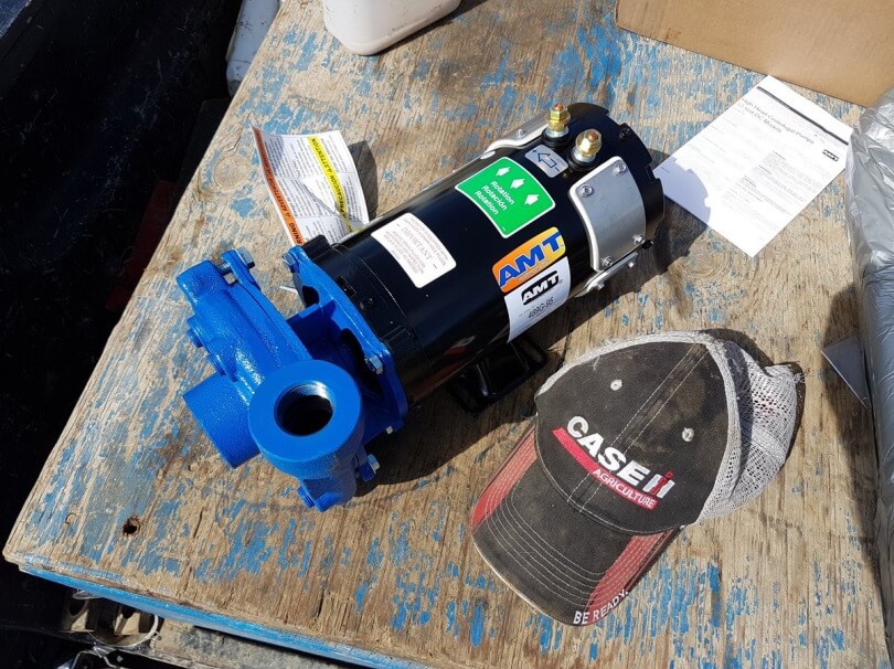
Uncertain about the hydraulics, David elected to use an electrical pump, but had difficulty finding one that would produce enough pressure and flow. Most electric pumps were too small and it would have taken more than one, plumbed in parallel, to achieve the volume numbers required. However, David found a high-flow 489G-95 AMT High Head Washdown Pump (1 HP, 1-1/4×1 IN/OUT, 12 VDC,Cast Iron,Buna-N) which he got from the US for about $1,200.00 CAD. Max flow was 56 gpm.
Note: In 2020 this pump model changed to the 12DC-95.
He removed the majority of plumbing, valves, and related complexity from the old rinse system. The Continuous Rinse was comparably simpler and isolated from the rest of the sprayer plumbing. It just involved a fill line from his two clean water tanks, the new rinse pump, and the existing rinse nozzle inside the product tank.
When the product tank empties, David holds down a push button dead-man switch he installed to activate the rinse pump. If he wants to do a more thorough job, he flushes the product tank and plumbing for about two minutes, then stops, gets out and opens the boom end valves. Then he climbs back in and does another one minute flush.
Approximately 30 gallons of water go through on each flush and my only issue is that I waited so long to install the system.
Author’s note: Positive displacement electrical pumps (which have zero risk of seal loss) are reasonable alternatives to centrifugal pumps. Depending on the size of the sprayer, multiple pumps plumbed in parallel can provide sufficient flow. We elected to use two Hypro electric roller pumps (model 4101 N-H) for the 2016 RoGator 700 installation. Cheaper, low amperage 12V diaphragm pumps from Delevan and FLOJET with capacities of 5-8 gpm are also available.
John Deere 4830 (Hydraulic)
Russ Enns (@EnnsFarms) from Saskatchewan installed a Delavan HD Magnum 125 hydraulic driven pump (1-1/4” suction, 1” discharge, 5-7 gpm of hydraulic flow). He mounted it on the same mounting plate as the main product pump, just on the opposite side, using the same bolt holes.
It was tied hydraulically to the main product pump, so the rinse pump could only run when the product pump was operating. The hydraulic supply from the sprayer went through an electric/hydraulic block via a solenoid resting in the closed position. A rocker switch in the cab used 12V to activate the rinse pump from the cab. Return hydraulic pressure from the rinse pump was tee’d into the main solution pump hydraulic return.
The clean water intake for the rinse pump was tee’d into the factory rinse tank. The discharge side of the rinse pump was plumbed to a check valve and tee’d into factory tank rinse system. Here’s the discharge line, check valve and tee into factory rinse (below).
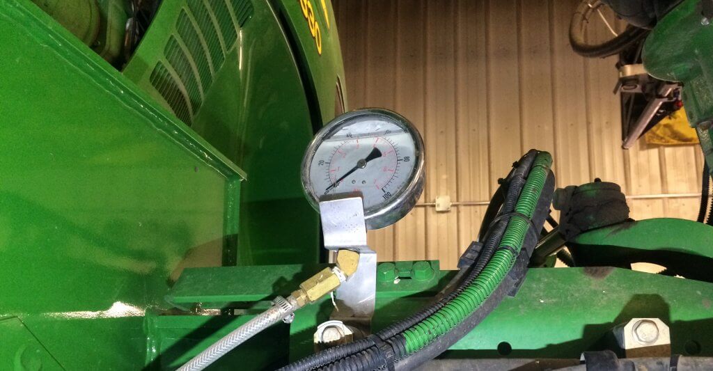
Russ mounted a large pressure gauge on front right axle to monitor rinse pressure. It’s easy to see from the cab, and easy to tell from the pressure when the rinse tank is empty.
In this case, Continuous Rinse is used in tandem with an Accu-volume tank gauge so Russ could monitor the level in the main product tank from the cab. Depending on the nozzles being used, he found that the rinse pump supplied clean water faster than the rinsate could be sprayed.
So, after finishing a field (or changing chemical, etc.) Russ turned on the rinse system while spraying the rinsate out on the field. The Accu-volume alerted him if clean water was accumulating in the product tank. If it got to ~20 gallons, he would briefly suspend the rinse pump while spraying to allow the level to drop. Then, he would start the rinse pump back up. He repeated this process until the clean water tank was empty.
Russ had many of the main components on hand, but estimates replacement value at ~$1,200.00 CAD. He noted that while installation was straight-forward, he originally piggy-backed the rinse pump’s hydraulic supply off the main solution pump, and it didn’t work correctly. We did that too, Russ 🙁
“Time savings and environmental considerations are the biggest benefit of this system to me. Being able to finish spraying a field, and immediately start rinsing and spraying the diluted solution is a huge time saver. I feel it’s a far more thorough rinse and a better/quicker dilution rate compared to how I previously handled rinsing and spraying out the diluted solution. Another benefit is that even though it’s plumbed into the factory rinse, the factory rinse system can still be used normally if for some reason the continuous rinse pump quits.”
Gregson Trailed (Electrical)
Continuous Rinse isn’t only for grains and beans. Matthew Droogendyk installed two 12v pumps on his trailed vegetable sprayer that matched the flow of the main pump. They had an electrician install a box for switching the the pumps and two solenoid valves on at the same time.
They noted an issue when trying to prime the main pump after emptying the tank. If the tank was sprayed completely empty, the main pump took time to get primed again. This affected rinsing time as well as the balance between supply and demand. Through trial and error they determined that running the rinse pumps for 1 minute (~15 gal) gave enough time to rid the main pump of air. Then the flows matched at about 15 gpa. Re-priming took about 5 minutes, and then an additional 2 or 3 to rinse using about 45 gallons of clean water. They found there was no need to replace their original tank rinse nozzles.
Tank Rinse Nozzles
One of the challenges of installing continuous rinse is ensuring the tank rinse nozzles are capable of rinsing the entire solution tank interior at potentially low pressure and low flow. In 2019, Lechler released the ContiCleaner range of rinse nozzle. Four ISO colour-coded nozzles capable of operating from 2-5 bar (29-72.5 psi), with flows from 6.5-32.3 L/min. (1.7-8.5 gpm). This will enable operators to better match the rinse nozzle(s) to the clean water pump. Be aware they are very difficult to source in North America. We tried and weren’t able to get them.
Parts / Price List
The following two parts/price lists are in Canadian Dollars. They do not include tax or labour and prices change depending on where and when parts are purchased. As you have read from the operators that installed their own Continuous Rinse systems, there are many possible solutions, so these lists are provided only for reference. Click the link to download a PDF.
Before contacting them, have the following information on hand:
Sprayer tank volume (both product and rinse, if applicable)
Boom length
Nozzle spacing
Largest nozzles mounted/used on the sprayer (excluding fertilizer nozzles)
Power available on sprayer (e.g. 12V available? Max amp? Hydraulic capacity?)
Thanks to Russ Enns, David Kucher and Matthew Droogendyk for sharing their install stories. Thanks to Adam Beaumont and Ehrin Frid for the Case IH and RoGator installations, and to Mike Cowbrough (@cowbrough) of OMAFRA and the Ontario Soil and Crop Improvement Association for collaborative support.
It’s finally that time of year to put away the most-used piece of farm equipment, the sprayer. Winterizing is a necessary step, but also an opportunity to do a few extra things.
Winterizing
Before you do anything, walk around the sprayer and note any telltale signs of liquid leaks. Once washed, the helpful dusty surfaces are gone and slow, chronic leaks may go unnoticed.
Now it’s OK to clean and rinse the sprayer tank and wash the sprayer exterior.
Drain any remaining water from the product and the rinse tanks. These remainders will cause unwanted dilution of the antifreeze. After you drain filter housings, inspect and clean filters.
Choose your anti-freeze. Automotive anti-freeze works, but’s it’s toxic and you can’t spray or drain it on the ground. Liquid fertilizer is sometimes used, but it’s corrosive, crystallizes when cold, and is not recommended. The best product is RV Antifreeze. It’s friendly to rubber and plastic, considered non-toxic, and can protect down to the coldest temperatures. Some dealers carry specific sprayer antifreeze. Don’t use fertilizer (e.g. 28) to winterize – especially with PWM systems.
Add between 25 and 50 gallons of antifreeze to the product tank, or if you have one, to the clean water tank. Most larger sprayers need at least 25 gallons just to prime the plumbing.
If you have a rinse tank, start a normal rinse procedure. Run the product pump, drawing from the rinse tank and pushing the material through the wash down nozzles into the product tank. Once the rinse introduction is complete, an automatic rinse procedure may subsequently open various lines leading to the tank as it swirls the rinse solution through the tank. Familiarize yourself with the specifics of that process.
If rinsing valves are manually controlled, once the antifreeze is in the product tank, run the pump, drawing from the tank and circulating back to the tank via agitation. If you have any other bypass lines, such as sparge, make sure the valve is opened. Run for two to three minutes.
If you have an on-sprayer eductor system, run the antifreeze past it and activate the eductor wash process.
Now, it’s time to push the antifreeze to the boom. Treat this like a boom cleaning, making sure the antifreeze gets to each nozzle body. If you have high- and low-flow options, open them to ensure the bypass gets the antifreeze.
Activate one boom section at a time and ensure all nozzles have received the antifreeze. Open nozzle end caps and allow the antifreeze the push out the water that is trapped there. It helps if you first purge the system with compressed air, then you don’t need to wait for the clear water to gradually change colour as the antifreeze arrives.
For extra points, rotate the nozzles through each position. As with cleaning or servicing, a remote-control boom section controller is invaluable here.
Remember to activate the fence row nozzles if you have any. These usually have their own dedicated feed line coming off the outer boom section.
If you filled your anti-freeze directly into the rinse tank, briefly open the rinse and product tank fill valves to allow anti-freeze to push out any water. Don’t forget the front fill line.
It’s OK to leave any leftover antifreeze in the tank. Next spring, collect it for re-use in the fall. You’ll still need more but this saves you some.
Don’t forget to also winterize your spray tender and any other transfer pumps.
It’s always a good idea to grease fittings after equipment is washed, to displace any water that got in, and to lubricate other moving parts that should be protected from corrosion.
Inspecting and Reflecting
You’re going to be looking closely at a clean sprayer, and this is a good time to spend a few extra moments to ponder the big picture. But first:
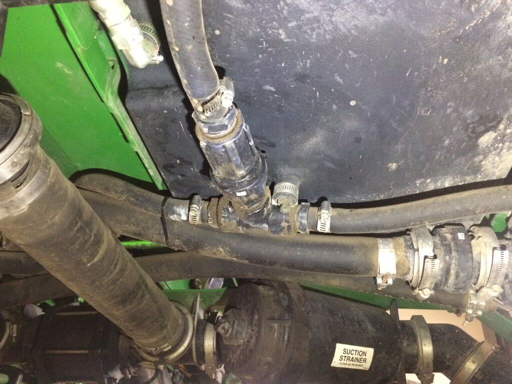
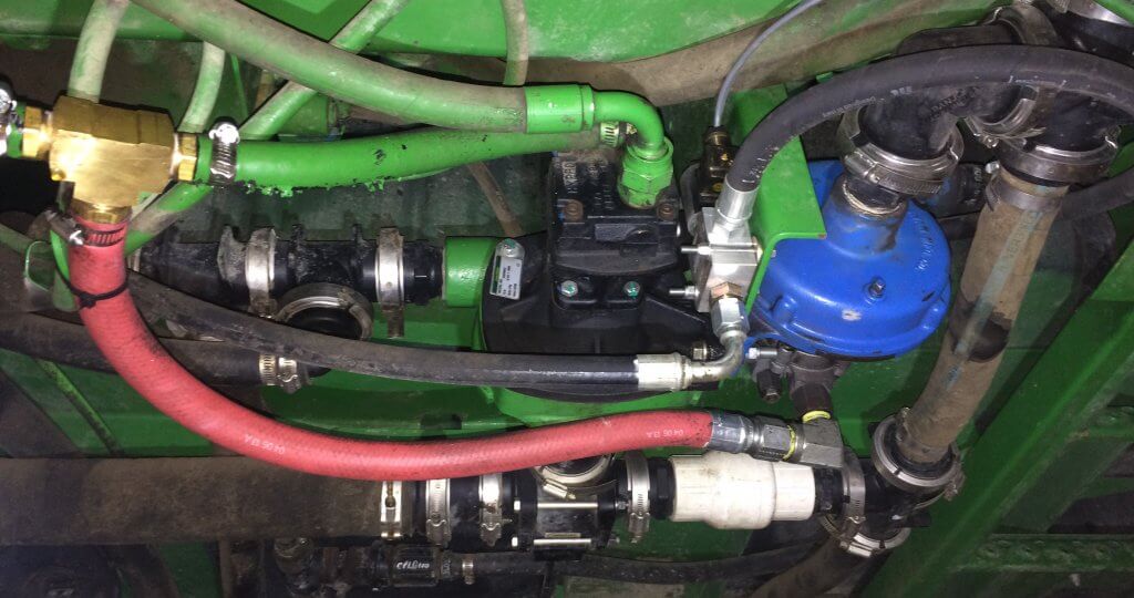
Inspect the full length of all hoses. Look for kinks, rubbing, small leaks, loose or defective clamps, valves, nozzle bodies. Tighten what’s loose, replace what’s worn.
Check cabin air filter service interval. Most new sprayers have activated carbon filtration that requires regular replacement. Activated carbon starts deteriorating with any air contact, so if you get a new one, leave it wrapped in its plastic until you need it.
Download or record sprayer performance data. How many engine and spraying hours? How many acres? How much water? A typical sprayer may calculate your acres per hour, but uses spraying hours only which paints a rosy picture. Do the calculation using gross engine hours to get a better idea of time lost to idling, transporting. Compare to previous year, perhaps set some goals.
Check with the dealer to make sure you’ve got the latest controller software version. Many systems get an upgrade during the off-season, so check back in the spring.
Remove the flow meter from the system and ensure it runs free. Do not use compressed air to run the impeller, this can ruin it. Simply blow on it and ensure it runs freely. This is an important part of the sprayer, so some people store it separately over winter. Did it provide accurate information?
Top up the fuel tank to prevent condensation.
Don’t forget to mouse-and bird-proof.
Now:
Think back on the season. What went well? What went poorly? What repairs were needed? Which ones did you put off? Are you happy with your procedures for filling and cleaning? Did you hear or read about improvements that seem interesting? Reminisce by reading the notes you wrote on your cab windows.
Make a list of the improvements that would address the main issues you came up with during your reflection. Is it time for a better filling setup? Do you need a whole tender system, or just an upgraded fill pump or a better inductor? Is it time to add a continuous rinse system?
Replacements and Improvements
Some sprayer components simply wear out and need regular replacement. A rule of thumb for sprayer nozzles is about 30,000 acres for an average sprayer speed and boom width. But before you buy, make sure you know what you need. Were you happy with the spray performance? Did you have more drift than you wanted, or poor coverage? As our cropping systems change, we may need different nozzles to suit the purpose. Now is the time to think about that very coarse low-drift nozzle that would have allowed you to get the spray on before the rain that delayed you for 3 days. Or the higher volume spray that would have done a better job with desiccating the tall canola crop, speeding up harvest. Or the finer spray that works better with the contact products you need to manage resistance.
Pumps can also wear. An impeller replacement can revitalize a centrifugal pump and give back more pressure and flow. Or a new pump with run-dry seals can avoid downtime from a pump failure in the middle of a good stretch of weather.
We still see plastic boom lines on some sprayers. Replacing them with stainless steel eliminates warped lines and makes spray patterns more accurate, improves cleanout, and adds sparkle.
A wider boom can dramatically increase productivity. After-market booms are available in 135′ and larger widths. Aluminum construction keeps them light, and corrosion-free.
Pulse Width Modulation (PWM) can be retrofitted on any sprayer. This will offer improved sectional control resolution, turn compensation, and better droplet size control.
Spot spraying can be added to any sprayer, and this will save 50 to 75% of pre-seed product use. In the case of WEEDit Quadro, these systems now come with stand-alone PWM that will work for general broadcast spraying in crop, with all the features mentioned above. Trimble offers the WeedSeeker II, it’s also feature rich but doesn’t offer PWM.
Become part of a mesonet. Most crop imaging services and some agronomic service providers offer weather stations, and obtaining one can make you part of a large, high resolution network. Local monitoring of temperature, rainfall, and wind conditions improves spray decisions as well, and may even give you the ability to identify temperature inversions.
The sprayer will often be the first piece of equipment used in the spring. Preparing it for its next job starts now.
When I had to replace a pump on a small scale sprayer, I had a lot of questions about how they worked, their capacities, hose sizes, mounting solutions and fittings. I turned to the Pentair Hypro Shurflo catalog and found a very helpful guide on pages 2 – 10. This article summarizes the steps recommended in the catalog.
Select Pump Style
Sprayer pumps can be divided into two categories: Positive Displacement Pumps and Non-Positive Displacement Pumps.
Positive Displacement Pumps
These include Roller, Diaphragm and Piston pumps. They are self-priming and traditionally operate at high pressures. Flow from these pumps is directly proportional to the pump speed, which is why they require a relief valve and bypass line between the pump outlet and the nozzle shut-off valve.
Roller pumps : This is the most popular pump with farmers world-wide. The seal and roller materials should be selected based on their compatibilities with the pesticides.
Diaphragm pumps : These compact pumps are popular for use with abrasive and corrosive pesticides. Their oil-filled piston chambers protect the pump materials.
Piston pumps : Similar to car engines, these pumps are relatively low-flow and high-pressure and suited for use with handguns sprayers. The piston cup materials should be selected based on their compatibilities with the pesticides.
Non-Positive Displacement Pumps
These include Turbine (or Transfer) and Centrifugal pumps. They must be primed and traditionally operate at low to medium pressures, although there are models available that can go up to 190 psi. Flow from these durable pumps comes from a rotating impeller that feeds liquid through the lines instead of pumping “per stroke”. Therefore, if the outlet is closed for brief periods, the impeller spins harmlessly, so a relief valve is not needed.
Determine PTO Pump Drive
When selecting a pump, you must specify the shaft rotation. Hypro suggests two steps for determining the required rotation:
Eyes on the End: Face the rotating Power Take-Off (PTO) and determine if it is spinning clockwise (CW) or counter-clockwise (CCW).
Opposites Attract: The pump must rotate opposite to the PTO. For example, if the PTO rotates CW, then the pump must rotate CCW and vice versa.
You should also be aware of your tractors’ horse power, and in order to determine the size of pump shaft, you should know the spline dimensions (e.g. 1-3/8″ (6 spline) pto shaft or 1-3/8″ 21-spline pto shaft).
Determine Pressure and Flow Requirements
In order to size the pump, you have to know the sprayer settings, such as intended application rate, average ground speed, agitation requirements, etc. Most can be calculated form the following formulae (provided in US and Metric units):
Calculating Agitation Requirements
Liquids :
Tank Volume (US gal.) × 0.05 = Agitation Requirement (gpm) Tank Volume (L) × 0.05 = Agitation Requirement (L/min.)
Wettable Powders and Flowables
Tank Volume (US gal.) × 0.125 = Agitation Requirement (gpm) Tank Volume (L) × 0.125 = Agitation Requirement (L/min.)
If the sprayer has a hydraulic agitation system equipped with a jet, it multiplies the agitation output without the need for additional flow. For example, it might have a 1 gpm input flow and boost it to a 10 gpm output. This savings should be accounted for:
Therefore, if you calculate a 60 gpm requirement for agitation, and have a jet that boosts the output 3:1:
60 gpm x (1 / 3) = 20 (gpm)
Calculating Nozzle Requirements
Once the agitation requirements are accounted for, you have to account for nozzles. The calculations are a little different for each sprayer, but they amount to the same thing – Total flow in US Gallons per minute or Litres per minute. Here is the calculation for a boom sprayer. For an airblast sprayer, assuming you are spraying every row, substitute “Row Spacing” for “Boom width”.
Total Flow Requirement (gpm) = [Output (gpa) x Ground Speed (mph) × Boom width (ft)] ÷ 495
Total Flow Requirement (L/min.) = [Output (L/ha) x Ground Speed (km/h) × Boom width (m)] ÷ 600
When the flow requirement for agitation and the flow requirement for the nozzles have been calculated, they are added together. It is important not to under-size the pump, so always factor in an extra 20% to compensate for changes in performance (such as pump wear and slower ground speeds) and restrictions in the plumbing systems that can cause pressure drops between the pump and nozzles, as follows:
Finally, be sure to account for any other flow requirements, such as tank rinsing nozzles and hose length/diameter (which causes pressure drops), and have some idea how you want to place the pump relative to the tractor and sprayer. If you prepare all this information, you can quickly and easily discuss your options with the retailer and select the pump that best suits your needs.
For more information on various types of pumps, check out this article by Dr. Bob Wolf:
This article was co-written with Murray Thiessen, Consulting Agricultural Mechanic.
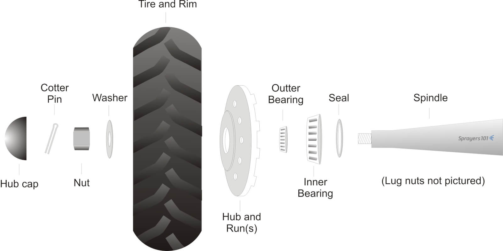
Sprayer wheel assemblies should be cleaned and inspected as part of regular annual maintenance. Wheel bearing maintenance before long-term storage may prevent water from corroding the bearings. The exploded diagram details the parts found in a typical trailed air-assist sprayer wheel assembly.
Exploded diagram of typical airblast sprayer wheel assembly.
The following procedure was performed on a 2012 Durand-Wayland sprayer by Mr. Murray Thiessen, Consulting Agricultural Mechanic and renowned “Sprayer Whisperer”. The steps are applicable to most sprayer makes and models. The entire process should take approximately half-an-hour per wheel.
Step 1
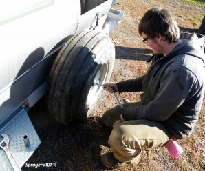
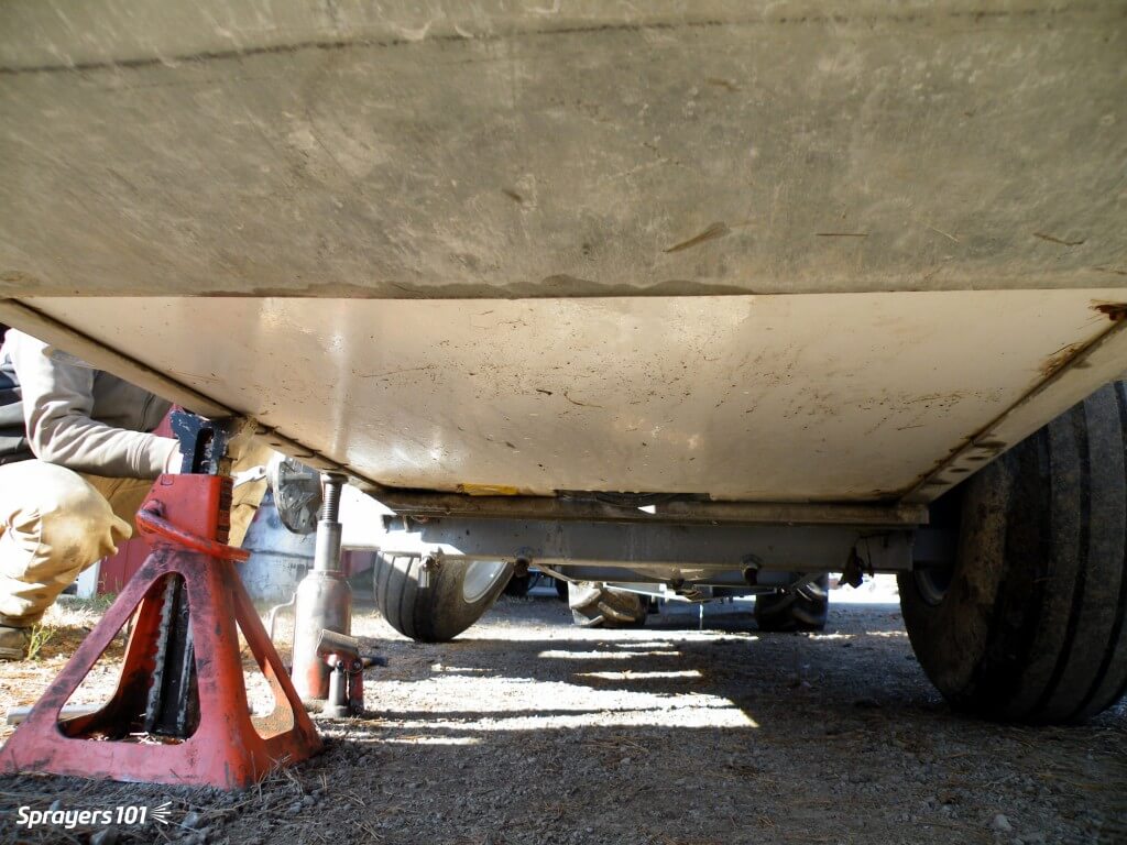
Empty the sprayer and park it in a well-lit, level spot. Un-hitch the tractor and raise one side of the sprayer using a bottle or floor jack to clear the wheel. Secure the sprayer with a jack stand.
Raise with one jack, secure with another.
Step 2
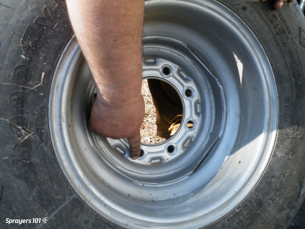
Remove the lug nuts and take the wheel off the hub. Do not remove the wheel and hub together because it is heavy and you might bang the delicate seal on the spindle. Check the wheel rim for signs of corrosion or distortion (often caused by either loose or over-tightened lug nuts). Check the tread for wear or cuts and check the tire pressure.
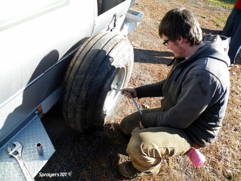
Remove the lug nuts and take the wheel off the hub.
Step 3
Remove the hub cap and pull out the cotter pin. Then remove the nut and washer that hold the hub on the spindle. Put all the small parts in a plastic container with some de-greaser (e.g. Varsol) to clean the parts and keep them from getting lost.
Remove the nut and washer that hold the hub on the spindle.
Step 4
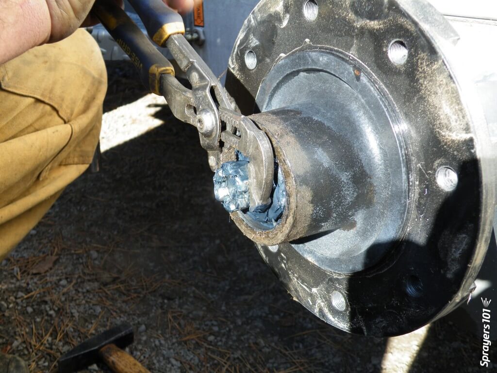
Knock out the seal and hub bearing and put them in the plastic container. Unless it is damaged, there should be no need to remove the bearing cup (or race) from the hub. The seal is designed to keep dirt out of the assembly, not to keep grease from escaping. Be sure to note which way it is facing. The seal is often ruined during disassembly; have a replacement on hand.
Knock out the seal and hub bearing.
Step 5
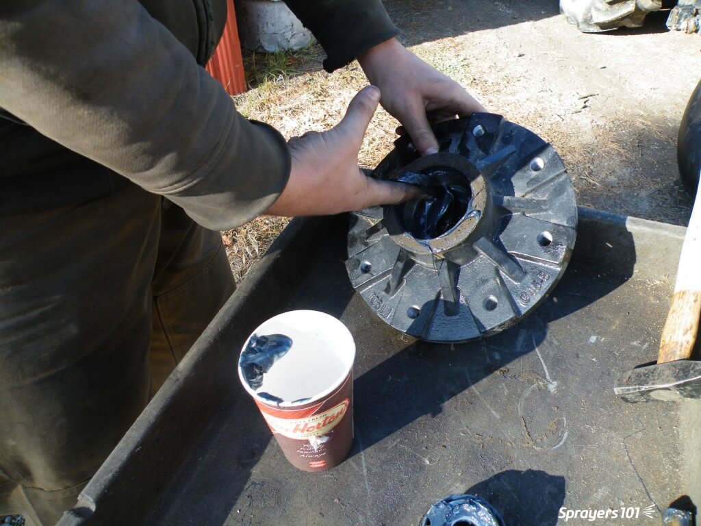
Clean the old grease out of the hub. This hub has too much and it has filled much of the air space (or cavity) within the hub. That air space is provided so grease is not forced out as the hub heats up, and so dirt is not pulled in as the hub cools. Note the colour of the grease – if it is black and stains your hands, it has burned because too much grease has caused overheating. Look for evidence of dirt or water in the bearing, which indicates seal failure.
Clean the old grease out of the hub.
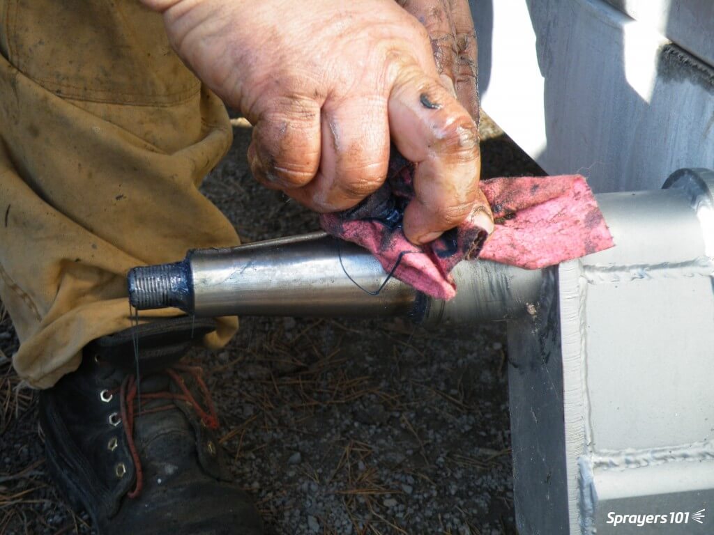
Step 6
Wipe dirt from the spindle. Never pressure-wash wheels when they are on the spindles because the spray drives dirt and water past the seal and into the hub. Inspect the sealing surface of the spindle for damage or wear.
Wipe dirt from the spindle.
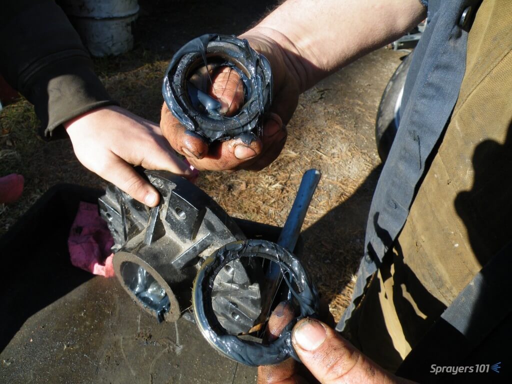
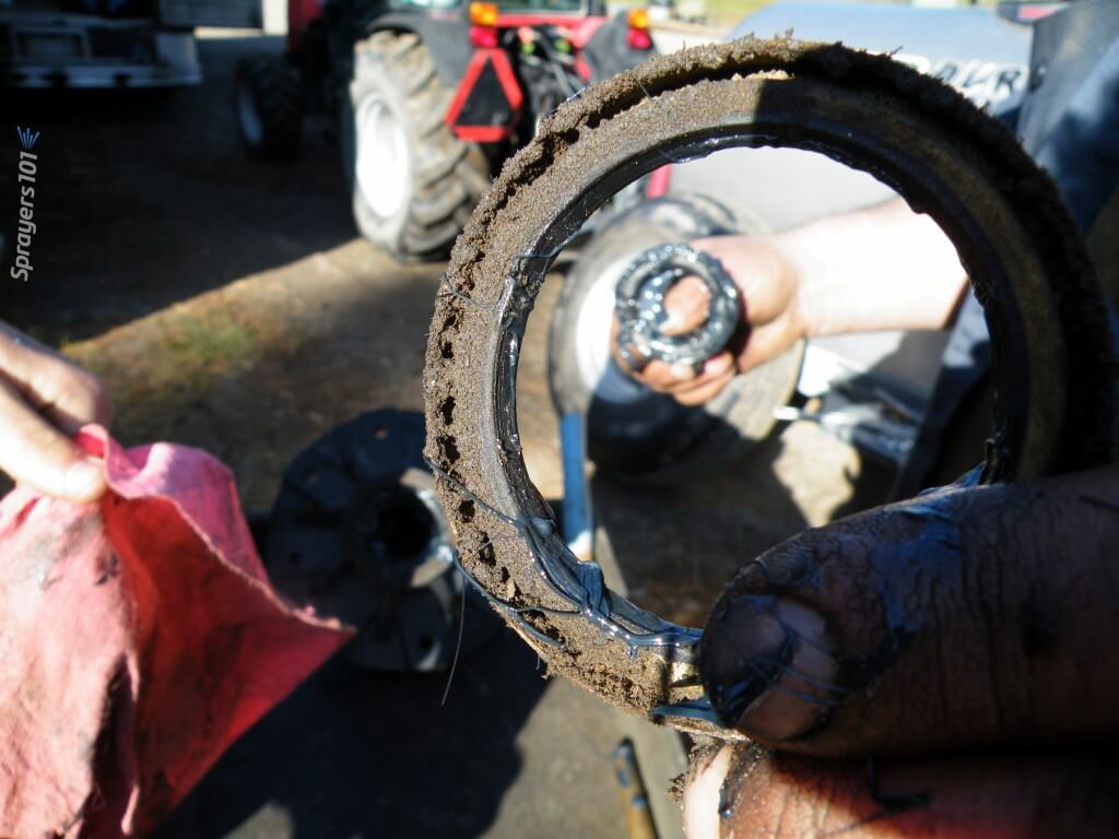
Step 7
Clean the seal thoroughly. Seals are easily damaged and may need replacement.
Clean the seal thoroughly.
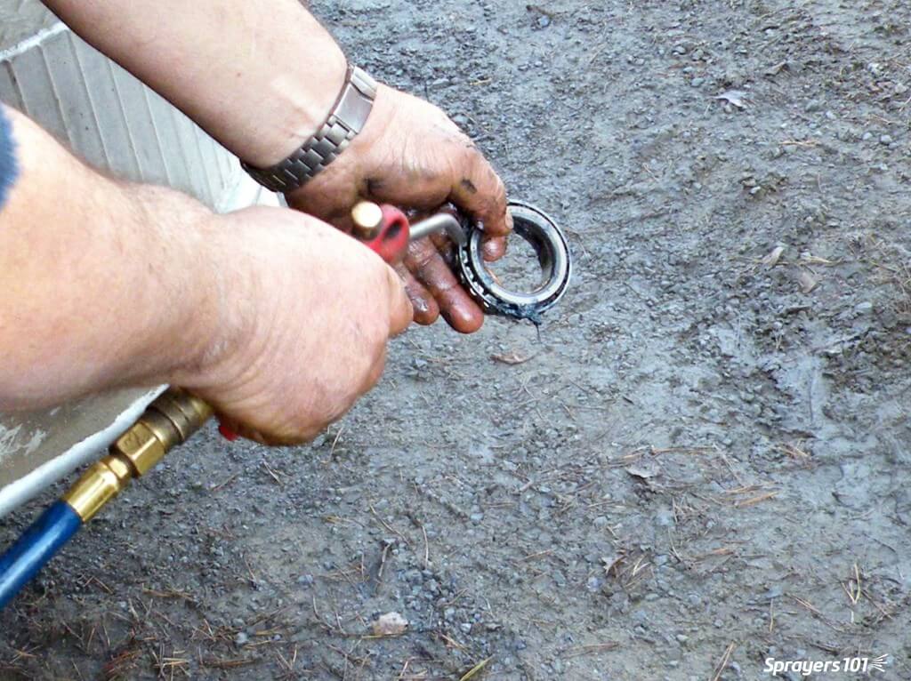
Step 8
Clean the hub bearing. Compressed air is a good way to get all the old grease out, but do not spin the bearing with the air.
Clean the hub bearing.
Step 9
Look for scratching, pitting or blue metal (indicating heat). This scorch mark indicates the bearing was moving on the spindle, and the friction created heat. Agricultural wheel bearings do not fit tight to the spindles. If there is too much clearance, the bearing race will turn on the spindle where it is not supposed to.
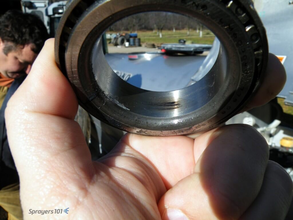
Look for scratching, pitting or blue metal (indicating heat).
Step 10
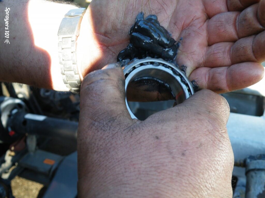
Repack the bearings, reassemble the hub and re-grease the hub. Bearings should only be ~40% full. Too much grease creates heat and does not let the bearing roll properly. Too little increases friction. No matter which grease you choose to use, never combine greases; they may not be chemically compatible.
Re-pack and reassemble.
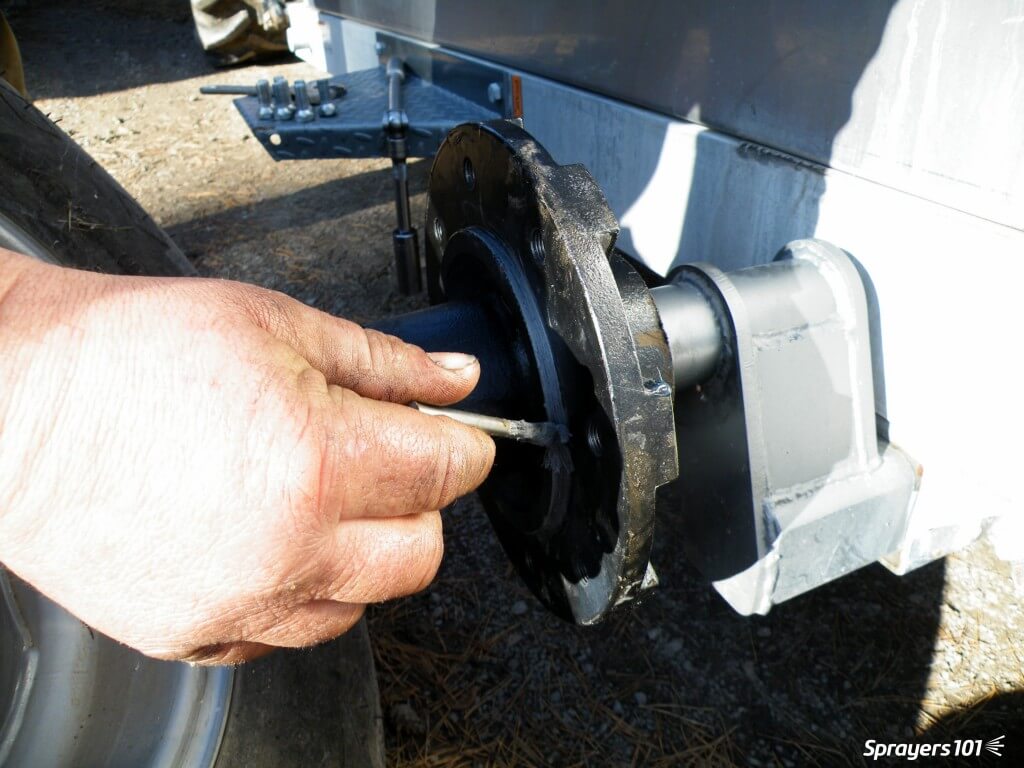
Step 11
Mount the hub tightly on the spindle. Replace the washer, cotter pin, nut and cap. There is no need to bend the arms of a cotter pin all the way back – it weakens the metal. Just bend one arm to 90° and cut off the excess. Use anti-seize on the wheel pilot to make the rim easier to remove next time.
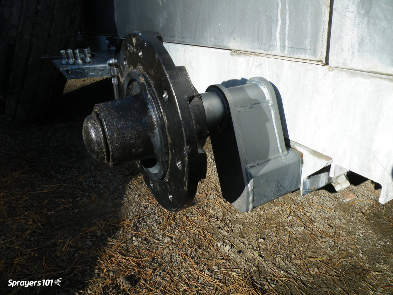
Mount the hub tightly on the spindle.Some airblast sprayers (such as this Durand-Wayland) have wheel assemblies that can be rotated to four different positions in the chassis. This will raise or lower the sprayer to better align it with the tractor hitch and PTO shaft.
Step 12
Replace the wheel and rim. Do not grease the lug nuts or they might loosen. Over- or under-torqueing lug nuts can cause damage. Look in the manual for your correct torque and consider using a torque wrench. Tighten the nuts in a star-shaped pattern – not sequentially.