Category: Calibration & Air Adjustment

All hort articles on sprayer calibration and air adjustment.

  • Optimizing Sprayer Air Settings – Part 2

    Optimizing Sprayer Air Settings – Part 2

    This is part two of a two part article on how to optimize the match between the sprayer air and the target canopy. You can find the first part here. For a more fulsome description of the process, consult chapters 3, 9, 10, and 11 of Airblast101.

    A close up of an airblast gear box. There are usually two options – high or low.
    A close up of an airblast gear box. There are usually two options – high or low.

    Evaluating air energy – Ribbon test part 2

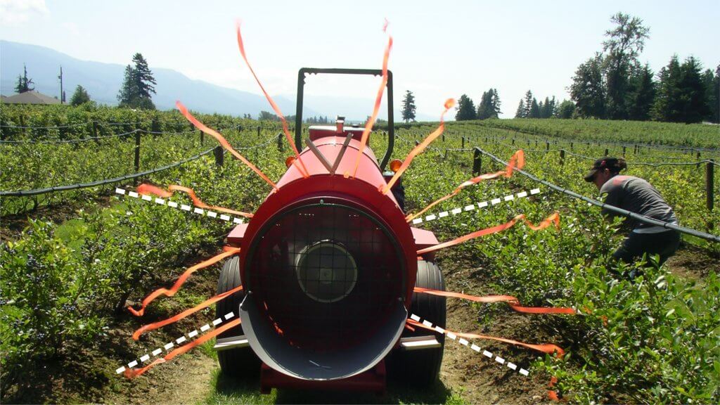
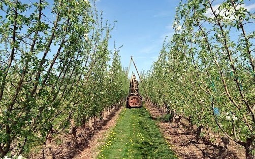
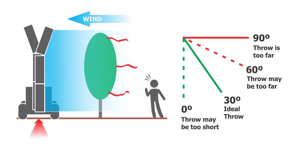
    Air behaviour can change radically between stationary operation and driving. We learned in part one of this article that slower travel speeds increase the throw and the spray height. The simplest way to monitor where air is going is for a partner to watch the leaves in the target canopy. Leaves that are ruffling indicate that air is reaching them.

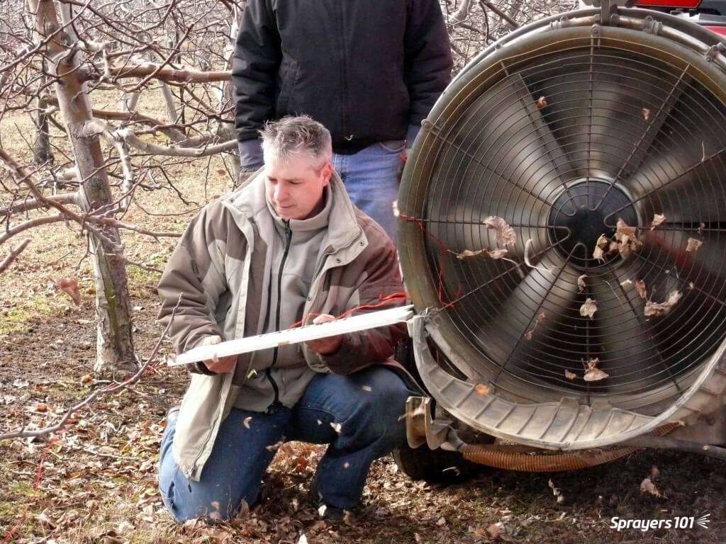
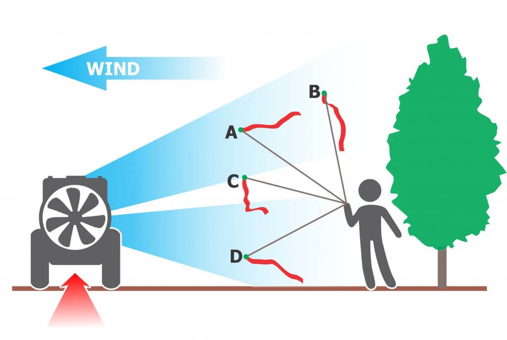
    A more informative method, and one that works during dormancy, requires a length of flagging tape tied to the end of a long stick. The partner (wearing eye and ear protection) can move the ribbon around in the air wash, extending it into areas of interest. The ribbon’s behaviour will indicate gaps, the air angle and relative air energy. The ribbon can be interpreted using the following figure.

    Work with the sprayer oriented to blow into any crosswind. Extend the ribbon into the sprayer air while the sprayer is stationary, or preferably, while driving. The ribbon’s behaviour will show what you couldn’t otherwise see. Here are a few possible outcomes: A. The angle and air energy are appropriate while the sprayer is stationary. B. The air energy is not sufficient to reach the tree top when the sprayer is driving. C. Obstructions or deflector misalignment can create gaps. D. Air is angled too low for the target canopy.

    Evaluating canopy penetration – Ribbon test part 3

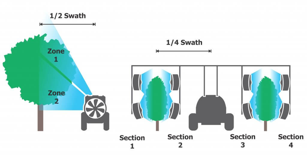
    This final diagnostic accounts for the influence of any intervening canopy (or canopies for multiple-row strategies). It confirms that the air energy has the potential to carry droplets the full extent of the swath. Evaluating one side will give you a lot of insight but if you have the time it’s better to do both sides. Since most sprayers have at least some imbalance in air handling, the results may surprise you.

    1. Choose a canopy that is upwind and on the lift side of the sprayer (if applicable).
    2. Move the sprayer a distance into the row to allow it to reach target speed and to avoid wind effects on the periphery.
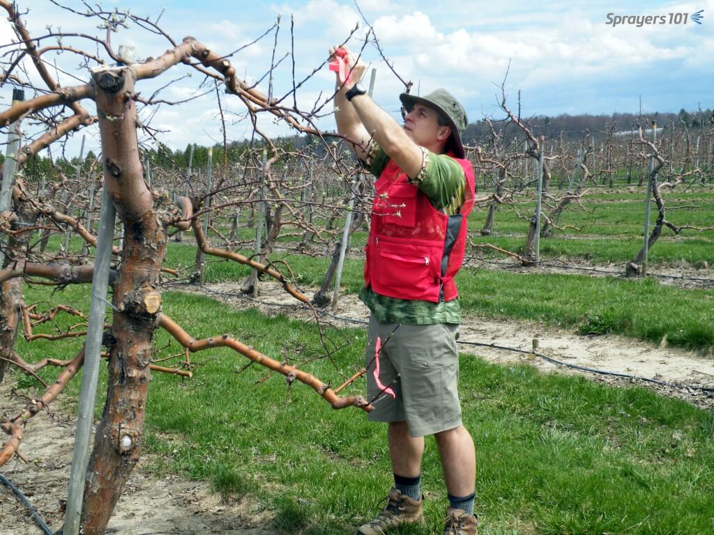
    3. Attach 25 cm (10 in.) lengths of flagging tape on the far side of the target canopy. Do this at the top, middle and bottom of the canopy. In tall canopies this might require a ladder, telescoping pole, or sections of galvanized pipe to raise the ribbons.
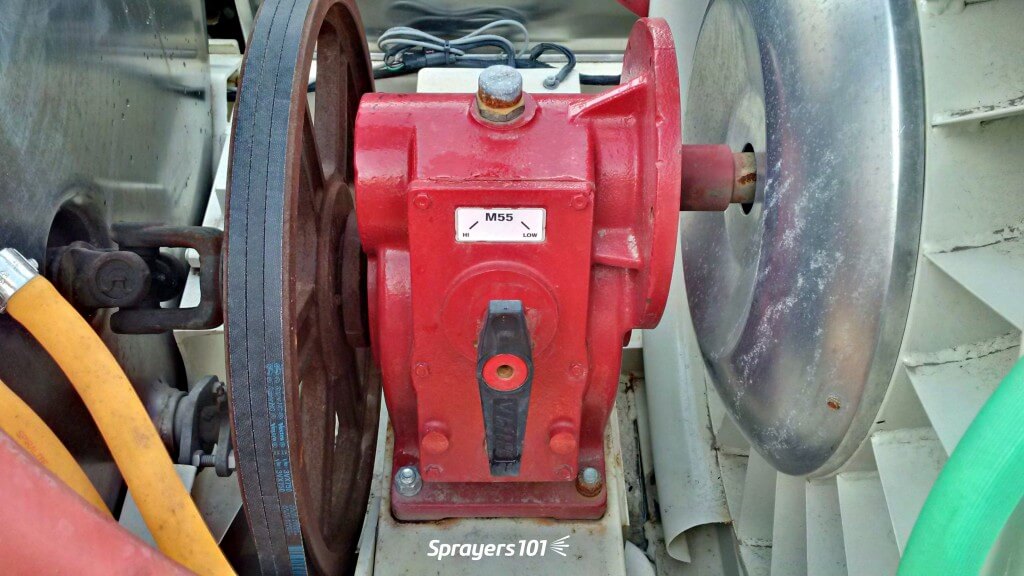
    4. With deflectors/spray outlets adjusted and the desired fan gear (or fan speed) selected, start the air without spraying and bring the sprayer up to the target travel speed. A partner wearing eye and ear protection will stand in the next alley and observe the ribbons as the sprayer passes (preferably recording a video for the operator).
    Three ribbons are positioned on the far side of the upwind target canopy. In this case, an every-row traffic pattern is depicted. The observer watches or records the ribbons as the sprayer drives past with the air on (not the spray). For an every-row traffic pattern, the air energy is too high if the ribbon strains at 90⁰. It is ideal for the ribbon to briefly flutter (0⁰-60⁰). If the ribbon does not move (0⁰), the air energy may still be sufficient as long as it penetrates to the centre of the canopy. This is often the case with particularly dense/wide trees like nuts and citrus.
    Tying flagging tape in trees to indicate prevailing wind and to calibrate airblast air settings.
    Tying ribbons on the up-wind side in an apple orchard just past green-tip. The red vest has lots of pockets to hold supplies and sprayer operators can see it clearly for safety. The Hawaiian shirt is because it was a Friday.

    Repeat this process this for EACH significantly different crop sprayed with the sprayer. As with air direction settings, multiple set-ups might be needed to reflect each block, or you might choose to group of similarly-sized blocks and calibrate air to the worst case scenario. Record the set-up for each sprayer/block combination and keep a copy in the tractor cab(s).

    Interpreting the ribbon tests

    Interpreting the ribbons is not always straightforward. When they don’t behave as anticipated they may be indicating one or more of the following problems:

    1. The air angle is incorrect.
    2. The air energy is too low.
    3. The air energy is too high.

    There might be a single cause or several contributing factors. As you diagnose and attempt to correct these problems be aware that addressing one may create others. If the problem cannot be corrected, the sprayer configuration (or design) may be inappropriate for the canopy or the environmental conditions.

    Ribbons that don’t point from the sprayer to the canopy may indicate a misalignment of spray outlets or deflectors. The bottom of the air should align with the bottom of the target. More critically, the top of the air should slightly overshoot the top of the target. We want to avoid spray drift, but we must account for wind speed increasing with height and vertical booms that rock on uneven alleys. If the spray does not slightly overshoot the top of the target, it may miss it entirely.

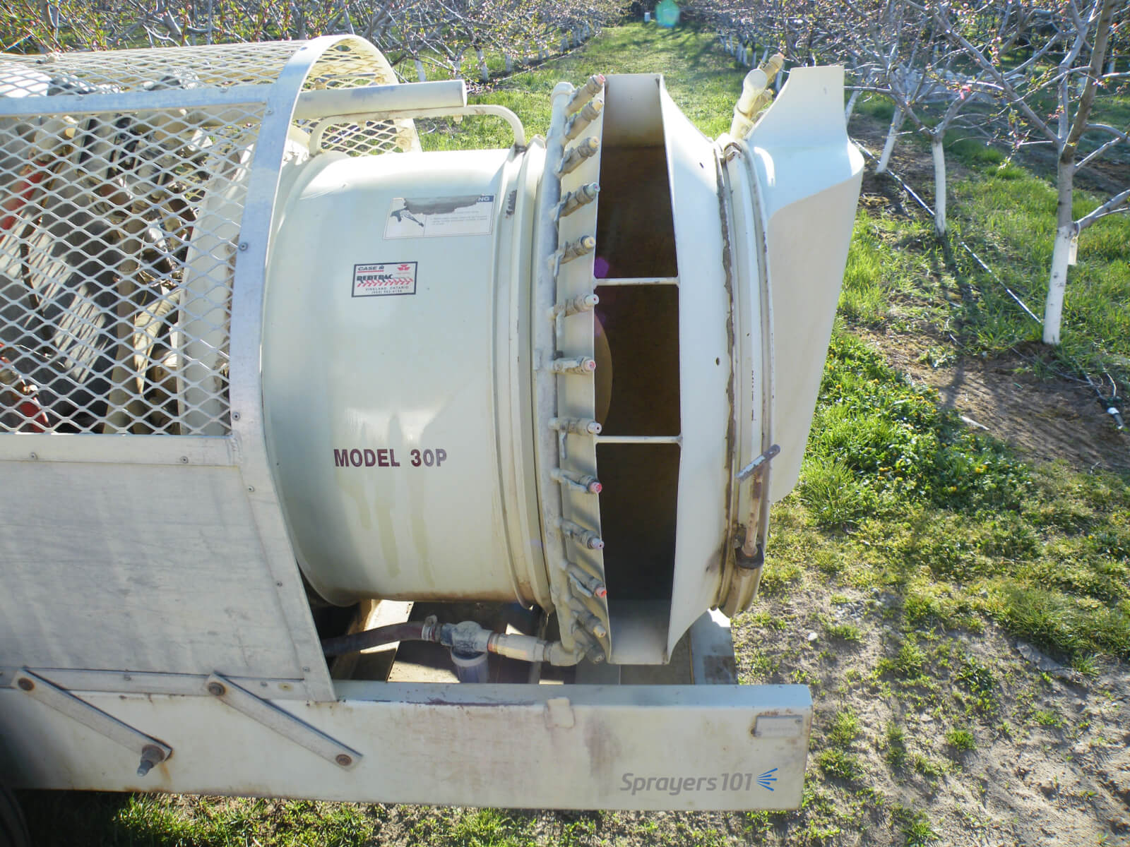
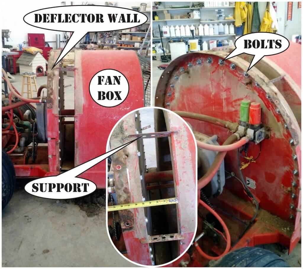
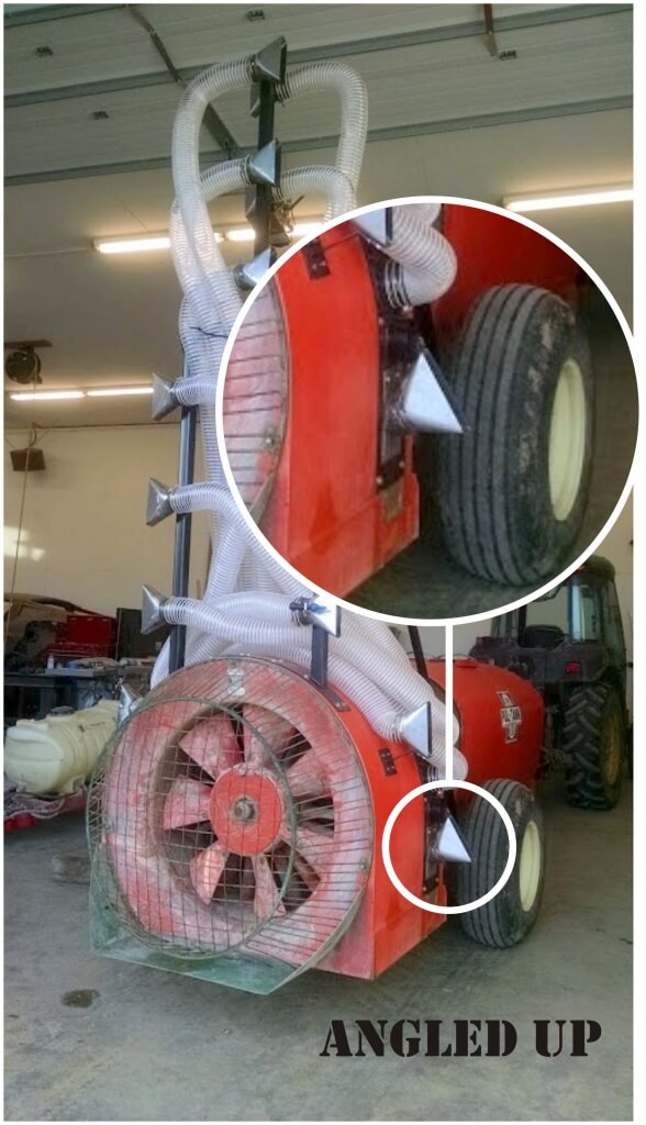
    Adjusting horizontal alignment, when possible, can significantly impact sprayer performance. It can be tricky to optimize the angle because it represents the sum of several complicated interactions. Air outlets on wrap-around sprayers may be positioned too close to the target canopy to permit a ribbon test. However, you can still use the ribbon-on-a-stick technique to visualize how the air is behaving. Consider the following when positioning air outlets on either side of a canopy:

    Unresponsive ribbons are often observed during a ribbon test. Depending on where the ribbon is located, this may or may not indicate a problem. Ideally, the top ribbon should always move in response to sprayer air. In larger canopies, this location represents the greatest distance sprayer air must travel and the highest wind speed it will encounter. The middle and bottom ribbons may or may not move in response to sprayer air. This is common in larger, denser canopies. To confirm this, an observer would have to stand at the trunk and watch the leaves rather than the ribbons.

    Shingling and canopy distortion

    When possible, do not position laminar air outlets in direct opposition. The convergence creates a high pressure zone that reduces spray penetration. Laminar flows will deflect unpredictably around this pressurized area and carry droplets back out of the canopy. Unless the canopy is narrow and sparse, turbulent air handling systems do not typically create this problem. In both cases, canopy penetration is improved when fans are staggered and/or are angled slightly forward or backward.

    When too much air is vectored directly at the canopy face, it may close and compress that canopy rather than penetrate it. This is more likely when air is high energy, has a narrow air wash or is more laminar in nature. When leaves shingle, the overlap blocks spray and creates resistance to sprayer air. Air will then take the path of least resistance and either deflect around the canopy or channel through any openings. Shingling can be corrected by angling air outlets slightly forward or backward. A little goes a long way as small changes can have big effects.

    Dr. Bernard Panneton (formally with the Horticultural R&D Centre, Agriculture and Agri-Food Canada) performed a series of experiments exploring the relationship between potato canopies and wind and his observations extend to all broad leaf crops. Bernard showed that as wind speed increased, the percent of leaf surface area exposed to spray also increased, but only to a point. If the wind got too fast, the percent of leaf surface exposed to spray dropped significantly: ~20% less!

    His interpretation was that low to moderate air speeds just ruffled the leaves, exposing their broad surfaces to spray more consistently. When air speed became excessive, leaves and twigs aligned with the wind, exposing only their thin edge to spray. The take home lesson is that spray will be more likely to impinge on all target surfaces when air speed and volume are calibrated correctly.

    Bernard summed this article up succinctly: “More air is not better!”

    Potato canopy distortion in an air tunnel. Research by Dr. B. Panneton.

    Video summary

    We’ll finish the article with a light-hearted video describing how the process works. It doesn’t explore the second ribbon test, but that’s more of a concern with distant targets or alternate row spraying strategies where the sprayer must penetrate one or more canopies in a single pass.

  • Optimizing Sprayer Air Settings – Part 1

    Optimizing Sprayer Air Settings – Part 1

    This is part one of a two part article on how to optimize the match between the sprayer air and the target canopy. For a more fulsome description of the process, consult chapters 3, 9, 10, and 11 of Airblast101.

    Why is air so important?

    Air handling is the most important and least understood mechanical system on a sprayer. Most air-assisted sprayers for three-dimensional perennial crops produce droplets that are Medium or smaller according to the ASABE S572.3 droplet size classification standard. These small droplets have very little mass relative to their surface area, so they don’t have much kinetic energy. Without air to impart speed and direction, most droplets would never go where we want them to. In addition, air opens and moves a canopy, exposing otherwise hidden surfaces to the droplets it’s carrying.

    Imagine throwing a feather. Now imagine throwing it as hard as you can. It may travel a little farther, but not much relative to the extra effort. Even then, an errant gust of wind might change its direction entirely. Similarly, we cannot rely on hydraulic pressure to propel small droplets. This is the primary reason for the “air” in air-assist spraying.

    Air-assist spraying attempts to replace the empty air within a canopy with droplet-laden air (and then get it to stay there). If we don’t have enough air energy, we won’t displace enough empty air and the throw will fall short. Likewise, if we have too much air energy, the throw will extend beyond the the target, wasting spray and likely compromising coverage. Ultimately, we want the air to expend all its energy, spreading, stalling and depositing droplets inside the target canopy.

    Travel speed

    Travel speed can have a significant impact on work rate. However, the effect of travel speed on air behaviour (and ultimately coverage) should be the sprayer operator’s primary concern. There will always be a trade-off between travel speed, coverage and work rate. Travel speed is the first and easiest adjustment to throw, spray height and canopy penetration. Just as travel speed modifies the liquid rate per row, it also modifies air energy per row.

    Environmental and canopy conditions

    Whenever calibrating or adjusting a sprayer, it is critical to do so in the crop, in environmental conditions you would typically spray in. You would not expect a sprayer to achieve the same results in high winds in a dormant vineyard as it would in calm conditions in a mature citrus orchard.

    I recommend using a handheld weather meter because local weather reports often don’t match the conditions in the planting. For temperature and relative humidity, take readings in the shade. For wind conditions, face into the prevailing wind and hold the meter as high as you can. Wind speed increases with height and we want to evaluate the most challenging part of the target – the top third of the canopy.

    Evaluating vertical air angles – Ribbon test part 1

    The air angle (or direction relative to the target) is the first concern. Research has shown that low profile radial airblast sprayers without effective straightening vanes or deflectors make the air go up on one side and down on the other. In extreme situations, this might compromise the spray job (e.g. miss the lower portion of the target on one side of the sprayer) or it might simply waste spray and stir up debris. Here’s how you can see if this is happening on your sprayer:

    1. Park the sprayer in an alley between the rows.
    2. Affix 25 cm (10 in.) lengths of tape along the air outlets. Tie them to nozzle bodies or use duct tape to position them so that they stand out in the sprayer-generated air.
    3. Bring the fan(s) up to the desired speed but do not spray. Stand back behind the sprayer and use the ribbons to extrapolate the air angle relative to the target canopy. Look for asymmetries and wasted air (i.e. angled above the canopy or into the ground.)
    The ribbons on the LPR sprayer in this photo are twice as long as they should be, but fortunately it was a calm day. Note the angles of the lower ribbons compared to the “ideal” broken white lines. The asymmetry corresponds to the misaligned bottom right deflector. Observe the ribbons while adjusting deflector positions. Any ribbons above the upper broken white lines indicate wasted air energy (and likely spray). Large upper deflectors, positioned horizontally, would reclaim wasted air and focus it into the crop.

    By observing the ribbons, you can extrapolate where deflectors or fan heads should be aimed. Air should be adjusted to slightly over- and under-shoot the target canopy. For ducted outlets, such as low profile Turbomist sprayers, the air outlet is not a uniform width – it’s widest about half-way down. Using ribbons to extrapolate air direction, aim the widest part of the outlet at the densest part of the canopy. This automatically repositions the booms as well, facilitating the next calibration step where we turn off nozzles that will significantly over- or under-shoot the target. This is discussed in another article.

    Using a piece of scrap wood with a ribbon on the end to demonstrate how deflectors would channel air on a Florida airblast sprayer. Once convinced, this grower fabricated and installed deflectors and has been very pleased with their performance.
    Using a piece of scrap wood with a ribbon on the end to demonstrate how deflectors would channel air on an Economist airblast sprayer. Once convinced, this grower fabricated and installed deflectors and has been very pleased with their performance.
    When repositioning the air outlets on a Turbomist with no towers, aim the widest part of the outlet towards the densest part of the canopy, then turn off unneeded nozzles. Lubricate the nuts and bolts that hold the outlet bands tight.
    When repositioning the air outlets on a Turbomist with no towers, aim the widest part of the outlet towards the densest part of the canopy, then turn off unneeded nozzles. Lubricate the nuts and bolts that hold the outlet bands tight.

    Video Extras

    These videos are a bit long-in-the-tooth now, but the concepts are still sound. If you hear anything in the videos that contradicts what’s written in the article, go with the article. Live and learn. Thanks to Penn State, the University of New Hampshire and Chazzbo Media for producing these 2014 videos.

    This article will conclude in the second half:
    Optimizing Sprayer Air Settings – Part 2

  • Homemade Air-Assist Tower Retrofit

    Homemade Air-Assist Tower Retrofit

    It was Saturday morning in April, 2016 when I received an email from Steven Bierlink, an orchardist in Washington State. He was curious about the impact of air induction nozzles on lime-sulphur applications (intended to thin apple blossoms). Work-life balance notwithstanding, I happily grabbed a hot cup of coffee and we got on the phone. It was a great conversation.

    The top two nozzles are capped in this orchard (targeting 10' and below). It's very evident that the top two nozzles are not in use.
    The top two nozzles are capped in this orchard (targeting 10′ and below). It’s very evident that the top two nozzles are not in use.

    It turned out Steve, like many growers, also had a knack for metal working. Displeased with his Rears sprayer’s performance, he told me he’d replaced his classic radial air outlet and curved boom with a ducted tower assembly, very much like the H.S.S. sprayer had just been introduced to North America.

    I asked if he would share his story and a few photos of how he did it and he didn’t disappoint! What follows is a photo journal of how he designed and built his new sprayer. He wrote:

    Sorry it’s taken me so long to get back to you. Spring is like a tornado and there’s just no time to get things done! Here’s a quick/not so quick rundown of the process:

    1 – I started by cutting the horizontal supports that attach the fan box to the front deflector wall. I plugged all the old holes with nuts and bolts to keep the air going where I wanted it.

    1) Fan box cut away from deflector wall. Holes filled with bolts.
    Fan box cut away from deflector wall. Holes filled with bolts.

    2- I then got a 10″ wide sheet of 16 ga cold-rolled steel from a local HVAC guy. I marked out where I wanted to attach it, drilled and tapped the holes, and attached using only stainless hardware. I marked out for a total of 8 holes per side evenly spaced, and drilled them out with a 4” hole saw. I then cut 3″ long sections of 4″ diameter thin-wall pipe (about 0.125” thick) and welded them flush with the inside.

    2) Welded pipe outlets for air.
    Welded pipe outlets for air.

    3 – I had several conversations with the local HVAC guy about turning vanes, nozzles, cubic feet/min. and wind speeds. The reason I decided to use hose after all these conversations is because there are no 90° angle turns. Those turns during testing severely decreased wind speeds because of the turbulence it caused. The hose is standard 4″ suction hose for woodworking chip/dust collection. Together, we came up with a 1.5” x 8” outlet to use. The numbers written on the outlet are average wind speed with 10 feet of hose attached at the desired tractor rpm’s.

    3) Commercial woodshop hose and air outlets.
    Commercial woodshop hose and air outlets.

    4 – Initially I was set on having the same distance of hose for each outlet, like headers for an internal combustion engine. I let that go since volume matters so much more in this situation and there is no “real” back pressure pressure to be concerned about. This was the initial drawing:

    4) Early sketch of equal hose lengths and positions.
    Early sketch of equal hose lengths and positions.

    5 – My measured dimensions showed the rectangular tower frame would fit through my tightest V-trellis, but only if I drove 0.5 mph and who is going to do that!? So, I needed to rethink it, break it down, and redo it. I decided on a partial, center-mast design.

    5a) Original tower frame would not clear the V-trellis. A center-mast solved the issue.
    Original tower frame would not clear the V-trellis. A center-mast solved the issue.
    5b) The top of the mast can be removed and the hoses disconnected and just left to hang. This allows me to hit 12' tall V-trellis easily, as well as 14' vertical trees all the way to the top.
    The top of the mast can be removed and the hoses disconnected and just left to hang. This allows me to hit 12′ tall V-trellis easily, as well as 14′ vertical trees all the way to the top.

    6 – After putting everything together I realized the air volume wasn’t always balanced across the each outlet. This was because the bend in the hose was too sharp and too close to the outlet. This REALLY MATTERS because if the air volume is too “heavy” on one side of the outlet, it doesn’t capture and carry the spray consistently. I corrected it by attaching support rods to increase distance between bends and outlets to about 18”.

    6) Gradual angles on hose prevented uneven air from the outlets.
    Gradual angles on hose prevented uneven air from the outlets.

    7 – On the painted, final design, you might notice lowest nozzle is angled. This is because I’ve noticed that foliar applications don’t often hit the lowest branches. I angled one outlet upwards to correct this. I notice in your article on the H.S.S. sprayer that the Woolly Apple Aphid nozzle does the same thing. I feel like I need to meet these people; we have incredibly similar ideas!

    7) Lowest nozzle and air outlet angled up to better hit lowest branches.
    Lowest nozzle and air outlet angled up to better hit lowest branches.

    8 – I used TeeJet’s ¼ turn AIC air-induction flat fan nozzles. They’re molded into the cap, so they are always oriented the right way. I set the nozzle bodies outside the air outlets to reduce turbulence in the airflow. It also makes servicing cleaner and easier. I also ended up adding some shielding around the lower nozzles just in case someone loses focus and runs into something.

    8a) Shields prevent physical impacts to AIC (air induction) nozzles. Coverage map was created for 55 gpa in a 6'x14' vertical planting.Shields prevent physical impacts to AIC (air induction) nozzles. Coverage map was created for 55 gpa in a 6'x14' vertical planting.
    Shields prevent physical impacts to AIC (air induction) nozzles. Coverage map was created for 55 gpa in a 6’x14′ vertical planting.
    8b) Close up of nozzle location versus air outlet.
    Close up of nozzle location versus air outlet.

    I asked Steve to stay in touch and let me know how his spraying season goes with the new sprayer. I’ll add to this article as he checks in and lets us know how the sprayer holds up and what changes, if any, he wants to make in the future.

    July 2016 Update

    As promised, I checked in with Steve to see how the sprayer was holding up. Here’s what he had to say:

    “It’s awesome. Works fantastic. Very effective in windy weather without having to worry about drift. Also, it works perfectly for sunburn protectants because of how directed the application can be. It has held up well considering how many acres its gone through this year.”

    Of course, there are always a few hiccups. I’ll interject here to suggest that what Steve is about to note about thinning is not a reflection of his design. I believe many orchardists experience the same difficulties with their conventional towers, too. Steve continued:

    “A few downsides I’ve noticed throughout the season: For blossom thinning (lime sulfur), gallonage is critical to get the stamen of the flower burned sufficiently to prevent fertilization. Even when spraying ~100 gallons per acre with this sprayer, it wasn’t enough to effectively blossom-thin the fruit. Part of this may be because I’m now distributing the spray evenly through the entire canopy, rather than spraying up through the canopy below. Another downside is the droplets’ tendency to accumulate in the lower portions of the tree (since every droplet doesn’t hit foliage), and over-apply in those areas. My Sevin/NAA application this year definitely prove this theory as my lower branches were over-thinned.”

    So, what’s the final word on this cool sprayer mod?

    “Overall, it’s great, and with a few tweaks this winter will be even better.

  • Airblast Nozzles – On or Off?

    Airblast Nozzles – On or Off?

    Spray that is not directed at the target is wasted spray. Many pesticide labels specifically require the operator to restrict spray to the target canopy. Spray that escapes above the canopy is a significant source of off-target drift. Foliar applications that extend below the canopy are not efficacious and represent waste and lost productivity.

    A spring application or oil and chloropyfiros. Estimate of 50% waste (in red).

    Air carries spray droplets, so the first step in any adjustment should be to perform a ribbon test to ensure the air outlets are oriented correctly. This is achieved by adjusting deflectors (e.g. low profile axial), the air outlets on a tower, or the entire head on a wrap-around design with individual fan/nozzle combinations.

    Spray height should always exceed the canopy height by a small degree. This compensates for the increase in wind speed with elevation, the potential loss of spray height with faster travel speeds, and uneven alleys that cause the sprayer to rock, which changes the spray angle.

    Spray angles change as a sprayer rocks on uneven alleys. It is more important that spray is directed at the top of a canopy than at the bottom.

    It is less critical that spray align with the lower portion of the canopy. As air energy wanes, or as droplets begin to lose momentum, finer droplets will slowly fall, depositing on random surfaces. Coarser droplets will quickly fall towards the bottom of the canopy, settling primarily on upward-facing surfaces. This secondary deposition can also occur from the cumulative impact of blow-through from upwind rows.

    Once the air is aligned, park the sprayer in an alley. Stand behind the sprayer and extrapolate a direct line from each nozzle to target canopy. Nozzles that point at the canopy should be left on. Nozzles that point above or below can be blocked, or turned off via valves or rotating roll-overs. Some roll-over nozzle bodies can be swiveled up or down 15 degrees to fine tune the spray angle. An alternative would be to permanently rotate the nozzle body fitting in the boom line. When aiming nozzles using a roll-over nozzle body, be careful not to swivel them too far or the valve will partially close and compromise the spray pattern.

    Use a ladder when adjusting nozzles on a tower sprayer. Some sprayer chassis and tanks are designed to accept a climber, but even so they can be slippery. Please be careful.

    When extrapolating, remember that the centre of a nozzle only indicates the centre of the spray pattern. Cone and fan angles can span 60 to 110 degrees, depending on the influence of air. Therefore, even though the centre of the lower-most nozzle intersects the bottom of the target canopy, you may still be able to turn it off because the nozzle above has that portion covered.

    Adjust spray distribution across the boom at the beginning and roughly mid-way through the spray season to ensure the sprayer will uniformly cover the target with the optimal volume. These adjustments should account for both canopy growth and fruit set.

    For example, as the season progresses in an orchard, fruit may cause limbs to hang lower and warrant a new spray distribution. Turning on the bottom nozzle position will help, but it doesn’t account any increase in density throughout the canopy. You may need more volume distributed across the entire boom. Another example: as grape bunches begin to close, sprayer operators may direct fungicides exclusively at the fruit zone and not the entire canopy.

    Remember to always check coverage using water sensitive paper. It’s not worth saving a bit of spray if you’re missing a bit of your target.

  • Rate Controllers on Air-Assist Sprayers

    Rate Controllers on Air-Assist Sprayers

    There are many advantages to using rate controllers, but their primary role is to maintain a constant application rate. All sprayers change speed on hills, at row-ends, or in response to surface conditions. Since flow from an uncontrolled sprayer is constant, the application rate varies significantly (up to 40% in hilly conditions). Rate controllers compensate for changing speed by adjusting flow.

    Hilly operations create highly variable application rates. Changes in travel speed can translate to 40% variability in rate applied. Rate controllers adjust flow to compensate.

    Pesticide is not saved directly (since increased uphill rates already cancel out reduced downhill rates), but consider the pesticide label. Labels that list a range of rates are contingent on pest pressure and crop size, but also compensate for poor coverage from low-performing equipment. When coverage uniformity is improved, experience has shown that operators can safely spray at minimal rates.

    Experience has also demonstrated that when coverage uniformity is improved, pack-out benefits follow. Even a modest improvement represents a quick return on investment. Equally important, a more consistent application reduces the risk of higher residue levels on the uphill and improves crop protection on the downhill.

    Now, if you are wondering if a rate controller is right for your operation, or if you should just stop reading now, consult this handy decision support matrix:

    This decision support matrix will help you decide if a rate controller is right for your operation. Spoiler alert: It probably is.

    Rate controller categories

    The following table categorizes controllers based on how they control flow. The categories are successively more expensive and complicated, but there’s commensurate value. For example, while not specified here, high-end rate controllers offer value-added features such as as-applied mapping (a powerful management tool).

    DescriptionProsCons
    Good:
    Monitors and adjusts pressure. Uses math to assume flow.
    -Fewest moving parts.
    -Simple interface.
    -Lowest cost.
    System monitors pressure, but does not register flow. For example, if nozzle flow is restricted, back pressure increases. The controller will compensate to correct pressure, implicitly reducing flow, but the operator is not alerted to the actual problem.
    Better:
    Monitors and adjusts flow, not pressure.
    Alerts operator to changes in flow. Operator usually sets the percent error threshold a little high to ignore transient changes.System will not register pressure deviations. At threshold speed, pressure may drop too low. This can cause inconsistent check valve operation and spray pattern collapse. With tall booms, the top nozzles may close completely.
    Best:
    Monitors flow and pressure and adjusts flow.
    -Best likelihood of a consistent application.
    -Alarms or automatic compensation of flow and pressure (user sets hard stops).
    -Provides a low tank level warning.
    -Stores preset calibrations to quickly switch between blocks.
    -Highest cost.
    -Steepest learning curve.
    -More “wire-wiggling”.
    -Operators often choose to over-apply at low speeds as a tradeoff for uniform output and consistent atomizer performance.

    Rate controller adoption and components

    As we write this, less than 10% of air-assist sprayers have rate controllers. In the dark old days of the 1980’s, air-assist operators were ill-advised to install high flow, low pressure field sprayer controllers. That history of mismatched components and subsequent bad experiences continues to hinder widespread adoption.

    Today’s components, however, are specific to air-assist sprayers and have made installations easier and more successful. Do your homework and speak with the manufacturer (not necessarily the local dealer) to ensure the controller, and all its components, meet your needs. Let’s describe the components so you’re prepared to have the conversation:

    • Console
    • Flow meter(s)
    • Flow control valve (including electric boom shut-offs)
    • Speed sensor
    • Wire harness
    Examples of rate controller components.

    Console

    The console is the interface. The user enters criteria about the sprayer, the planting, and calibration data and receives information about sprayer performance. Select a console designed for air-assist sprayers and not field sprayers. Controllers intended for horizontal booms perceive swath in two dimensions, but air-assist controllers account for multiple vertical booms or boom sections in the swath (see the following figure).

    Field sprayer rate controllers used in vertical crops must be “tricked” when programming swath. Leading air-assist rate controllers can assign flow to zones on a single vertical section (left) and adjust swath (sometimes called width) for multiple booms (right).

    Flow meter

    With rate controllers, flow is detected by one or more flow meters positioned pre-manifold. The relief valve becomes more of a safety device, defining the high pressure limit and bypassing flow if required. Most rate controllers use a flowmeter with no ability to monitor pressure. While still effective, adding a pressure sensor ensures nozzles are operating in the desired pressure range.

    Turbine or paddle meters are inexpensive and acceptably accurate. They require periodic cleaning because some chemistry can accumulate and interfere with their moving parts. Filtration helps to minimize this issue. Magnetic or ultrasonic meters have no moving parts, higher resolution, wider metering ranges and aren’t affected by the viscosity of the spraying solution or entrained foam. However, they are considerably more expensive than mechanical meters.

    Flow control valve

    Unlike boom control valves that are open or closed, flow control valves are capable of a range of adjustments. Valve actuation is controlled by 12 volt servomotors. The level of precision depends on the style of valve.

    • Butterfly valves: Simple, inexpensive, and typically for pressures <10bar (150psi). Some have minor leak-by when closed. Control is less precise as the valve opens because the orifice gets geometrically larger. This gives a narrow metering range.
    • Calibrated ball valves: Versions available for all pressures. May be simple flow through balls with similar metering limits to a butterfly. A better ball design is also available that offers a linear flow rate through the entire adjustment range, offering more stable rate control over the entire flow range. Several manufacturers offer these. All ball valves offer zero flow when closed.
    Left- A butterfly valve. Right- A ball valve. Notice how a small change in the opening angle translates into a large change in the orifice size; this is difficult to control manually. Servomotors not pictured.

    Compared to field sprayers, air-assist sprayers travel slower and use lower flow rates. It is a mistake to employ valves intended for high-flow, high-speed sprayers.

    • Speed: Valves are rated by connection size (½”, ¾”, etc.) and opening time (e.g. 1-14 seconds are common). Many rate controllers can be programmed to optimize adjustments for the speed and size of the valve.
    • Precision: As control valves open over their 90° range, the ability to control flow is less precise. Slower valves give less precision, but greater stability.
    • Size: Valve size should accommodate maximum flow and no more. If the valve is too large, it can only meter flow over the first few degrees of opening. For example, let’s say a valve capable of 200 L/min (50 gpm) and rated 1 second is used. Your sprayer meters 0-20 L/min (0-5 gpm). This means the whole metering range happens in the first tenth of a second. Even lightning-fast consoles will give unstable readings (aka hunting) as the computer overshoots the target in an effort to comply.

    Control valves are “service parts”. Seals, moving parts and abrasive liquids mean they will require regular care and eventual replacement. It’s a wise precaution to make them accessible and easily removable. We suggest installing them with quick-connects (see top-right of the previous collage of rate controller components above) to make field-maintenance fast and easy.

    Speed sensor

    Speed can be based on GPS, engine tachometer readings, radar, or wheel rotations. Newer rate controllers may even take the speed directly from the tractor’s data feed. Price, reliability and crop conditions are all factors you should consider in the choice.

    • GPS: Easiest to deploy, very accurate (especially RTK-GPS) and reasonably priced. However, overhead canopy can block satellite signals. Some controllers compensate for the GPS losses with sophisticated internal kinematic devices that measure the inertia of the sprayer and calculate speed when the GPS is not reliable.
    • Wheel rotation speed sensors:  An entry-level sensor, it’s typically a reed switch or Hall effect sensor that detects either the lug nuts or magnets installed on the rotating wheel. More magnets improve accuracy. Its exposure makes it prone to physical damage, and readings change with tire radius (which changes as the tank empties, on soft ground and with temperature). This is why wheel sensors are calibrated in the alley, with the tank half full and both tires at the same pressure.
    • Radar speed sensors: Employing the Doppler effect to measure speed, radar is the most accurate sensor. They are unaffected by terrain, slope or tank volume. They can be mounted anywhere in sight of the ground. They are, however, the most expensive and are typically not repairable if they fail.
    • Tachometer speed sensors: Largely obsolete, they measure the tractor’s tachometer speed and convert it to travel speed. Difficult to install and prone to the same inaccuracy as wheel sensors.
    • Interface sensors: Relatively new, some rate controllers interface with tractor electronics to receive speed data. ISOBUS, the standard interface language that agricultural electronics are increasingly adopting, makes this data exchange more common.

    Wire harness

    It may seem we’re drilling deep to mention wires, but standards are changing. Many controllers employ traditional analog wiring, but they are being made obsolete by the newer ISOBUS option.

    • Traditional Analog: Simple wires with automotive or custom plugs designed to match components. Relatively inexpensive and sometimes field repairable, analog wiring carries signal voltage (and power) to and from the controller to drive valves and receive analog sensor data. Communication is one-way: Sensor to controller, controller to valves.
    • Modern ISOBUS: Bus systems are more like a computer network, where digital signals travel back and forth between the controller and each component. Components that require power are wired directly to a battery. This results in a greatly simplified harness. The controller’s single ISOBUS wire “daisy chains” all components to relay commands and receive status, which makes system monitoring and diagnosis easier and more effective.

    Conclusion

    Rate controllers are a worthy consideration for your existing or future air-assist sprayer. Assess your needs and work with a knowledgeable dealer or manufacturer that can assemble and install a system appropriate for your operation.