An airblast sprayer inspection is part of preventative maintenance. This daily activity identifies small problems before they become big ones. You can do it at the filling station, so it’s fairly convenient.
Don’t think of it as stealing time from your spray day… it’s part of your spray day. Don’t skip it. If time is tight there are many other ways to improve your work rate.
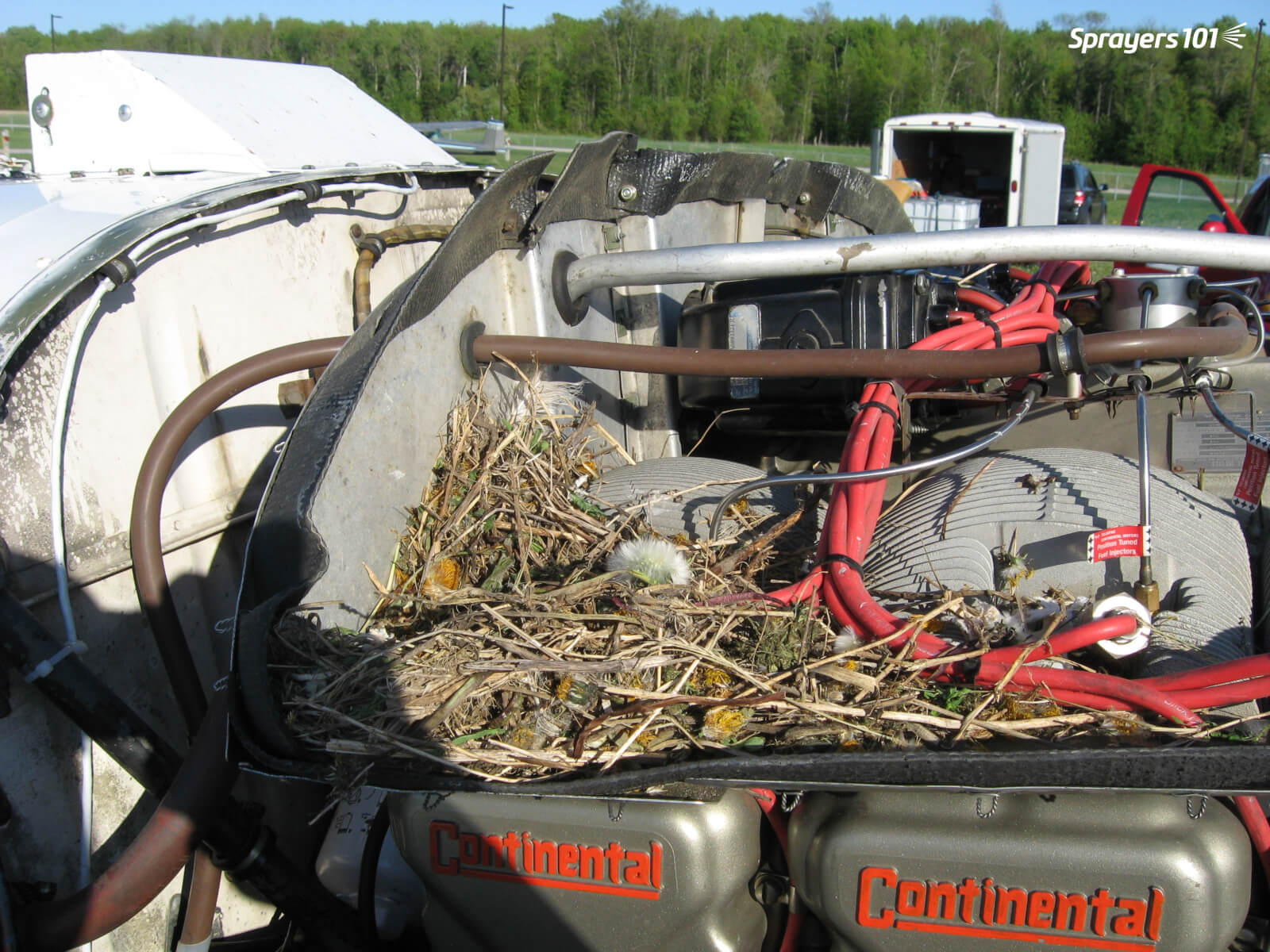
This spray plane was left on the runway with the engine exposed for less than four hours. When the owners returned they found a precocious bird had built a nest! Perform regular sprayer inspections – you never know what you’ll find. Photo Credit – S. Richard, New Brunswick.
Note: Always wear appropriate personal protective equipment (as indicated on the product label), including hearing protection.
Inspection steps
Follow this generic inspection process. If your sprayer manufacturer or manager advises additional steps, be sure to perform them.
Before filling
1. Work with a rinsed sprayer parked on level ground (e.g. the filling station).
2. Check lines/hoses and fittings for signs of wear or cracking. Leaks or bulging may only become apparent under pressure (see Test spray).
3. Filters, screens, strainers and nozzles are clean and unbroken. Leaks may only become apparent under pressure (see Test spray).
As a plastic suction filter ages, it can warp or become brittle. When this happens, the O-ring may no longer sit correctly and the unit may allow air to be drawn into the lines. They should be cleaned and inspected when the sprayer is rinsed.
4. Engage each nozzle shut-off valve or nozzle body flip position. They can seize or loosen with time.
Begin filling
5. Begin filling the sprayer 1/2 full with water.
6. For PTO-driven sprayers, confirm universal joint(s), sprayer-tractor hitch and all connections are clean, lubricated and secure.
7. Check that all guards (e.g. PTO shaft shield) are in place and intact.
8. Ensure fan blades are unbroken and scraped clean. Intake grill(s) must also be clean and unbroken.
9. When 1/2 full, stop filling and check tire pressure (tractor and sprayer).
Test spray
For multi-row sprayers, you may have to move the sprayer off the fill pad for the test spray; it’s easier with the air off, if possible. Perform the following steps:
10. Open the manifold valve to fill the lines and begin spraying clean water.
11. Ensure each nozzle sprays correctly. Get out of the cab to inspect, don’t just shoulder-check. This gives the opportunity to double-check for line-bulges and leaks.
12. Ensure the agitation / bypass system is functioning properly.
13. Check that the tank is secure on the chassis and both crack and leak-free.
Complete filling
Continue filling. Once the sprayer is back up to 1/2 full, mix products per usual. If your sprayer manufacturer advises contrary or additional steps for a sprayer inspection, be sure to perform them.
Sprayer inspections become repetitive, so it’s easy to accidentally miss things. Have you ever driven home while preoccupied, only to discover you don’t remember how you got there? Download our checklist to keep you engaged and to help ensure accuracy. Consider printing and laminating it for repeated use with a dry-erase marker.
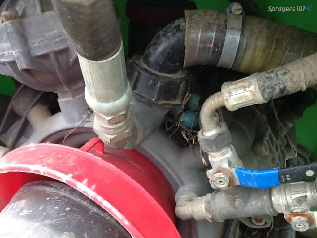
You never know what you’ll find during an inspection. I found a robin’s nest hidden on this vineyard sprayer’s pump.
Anyone that operates heavy machinery should perform a preventative maintenance inspection before using the equipment. It’s no different for airblast sprayer operators; embrace the daily walkaround.
Next to sprayer math, cleaning the sprayer is one of the more distasteful aspects of airblast spraying. It’s time-consuming, you never really know when you’re finished, and sprayer manufacturers and pesticide labels offer only limited guidance.
Clean sprayer rinsate often looks and smells exactly like contaminated sprayer rinsate.
When airblast sprayers are not cleaned as often or as thoroughly as they should be, it creates problems:
Unnecessary operator and environmental exposure.
Residue in (or on) the equipment can damage sprayer components.
Carry-over can deposit damaging or unlabelled residues on crops.
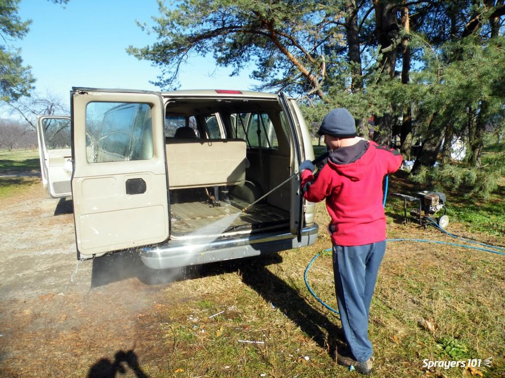
Keeping the airblast sprayer clean, inside and out, as part of the spray day. Ken Bell is pictured giving his FMC a bath. This picture was staged – he normally wears PPE and so should you.
Dr. Tom Wolf (Agrimetrix Research and Training), defines cleaning as two processes. Rinsing is the dilution of any remaining spray solution. Cleaning is rinsing with additional steps to decontaminate sprayer components (e.g. filters, nozzles).
Rinsing
1. Rinse ASAP
Don’t let residue sit in (or on) the sprayer, even if you plan to use the same product the next day. Multiple studies have shown that products adsorb onto, and absorb into, plastic and rubber parts. They form hard-to-clean residues when left to dry.
Think about cleaning oatmeal or egg yolk off dishes – it’s far easier if you clean them before they dry. Rinse right away, while the sprayer is still wet.
2. Minimize the volume remaining in the sprayer
Experience, sprayer math, and familiarity with airblast sprayer design helps minimize the volume remaining in the sprayer. Rate controllers and volume-monitoring systems (e.g. Ontario’s Accu-Volume) provide real-time feedback so the operator can speed up or slow down to empty in the right place. Minimizing any remaining volume makes rinsing far more effective.
Even an “empty” sprayer can still retain several litres of standing volume in the sump and lines. Operators should know this volume. Never Drive-and-Drain to empty standing volume onto the ground.
Standing volume from the booms allowed to drain to a holding tank via the bottom nozzles.
3. Dilute the remnant: The Triple Rinse
Rinsing the system multiple times with low volumes (aka The Triple Rinse) is more effective at reducing pesticide concentration than a single, high-volume rinse. See for yourself using this clever dilution calculator.
Once the sprayer is “empty”, use clean water to fill the tank to 10% of its capacity (or add 10 parts water to one part standing volume) for the first rinse. The use of such low volumes may not be possible with centrifugal systems where the tank must be filled above the top of the pump for priming. Know your sprayer design.
Agitate and circulate it through the entire sprayer for a few minutes. Spray out the rinsate and repeat the process two more times. Where do you perform this? Where does the rinsate go? Read on.
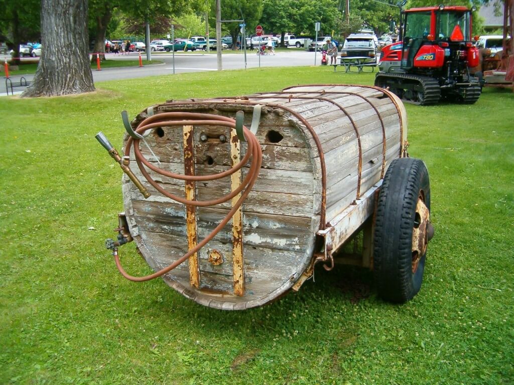
A wooden sprayer tank. You know that had to be tough to clean.
Where does the rinse water come from?
Nowadays, all airblast sprayers should include an onboard tank-rinse system consisting of a clean water tank and tank-rinse nozzles inside the tank. They may even include a pressure wand to rinse the exterior.
Sadly, most airblast sprayers do not have these features. But, aftermarket rinse kits are available. If you are considering installing a rinse system, check out the continuous rinse system.
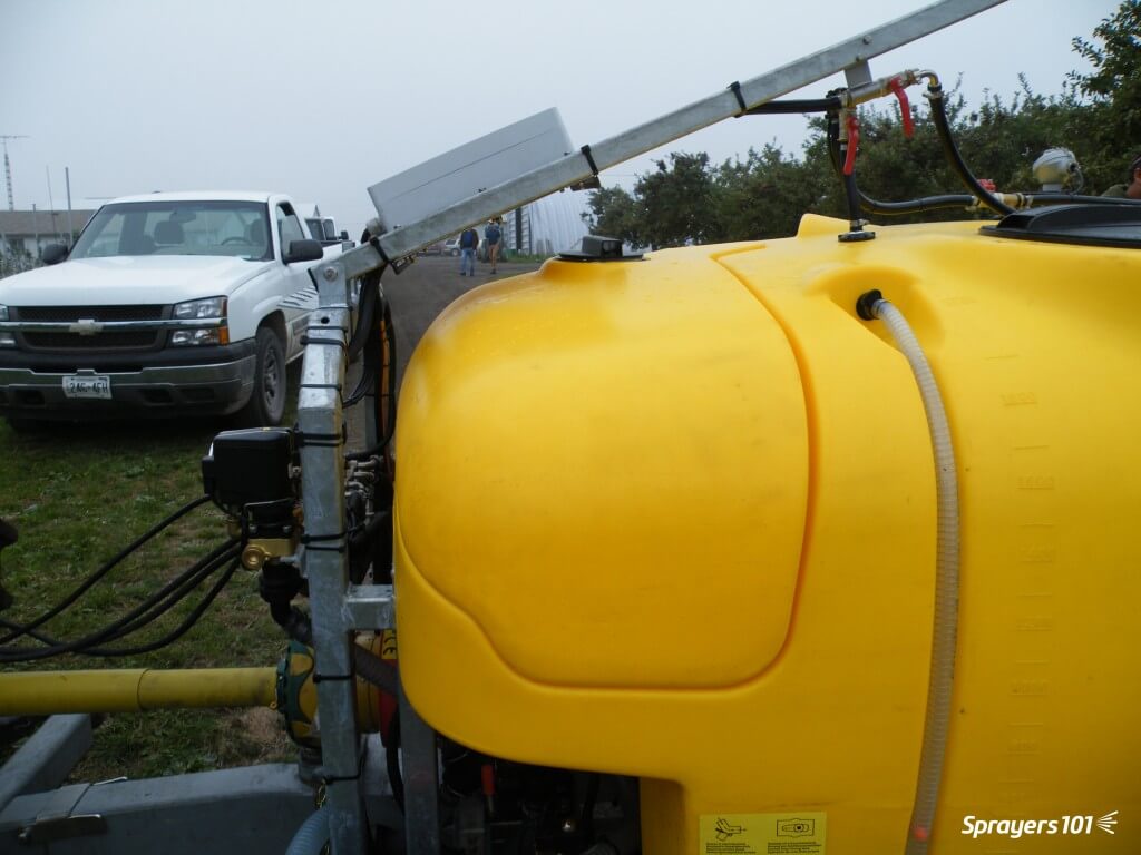
Left- Product-pump-powered water tank, Right- external-pump-powered water tanks. Images from Paolo Balsari’s (DiSAFA) “Sprayer Cleaning: Importance and Phases” at AAB Sprayer Cleaning Workshop, Oberbozen, Italy. October 2019.The Hol features a separate 150 L tank to supply clean water to its automatic tank rinse system.
Alternately, the clean water for this process can be carried on a support vehicle or sourced from holding tanks strategically-located near the planting.
Where to rinse
Precautions must be taken to ensure rinsing is performed away from wells or open water. It is best to perform the triple rinse in the crop that was just sprayed. The dilute rinsate can be flushed through the lines and sprayed out through the nozzles onto the crop. You can choose to overspray treated areas again at a lower dose (label permitting), or use a hedgerow or target row that has been set aside for this purpose.
As regulatory agencies concerned with environmental contamination re-evaluate chemistries critical to horticulture, it becomes even more important for airblast operators to manage rinsate responsibly.
While it is best to rinse the sprayer exterior in the planting as well, most return to the farm. Too often, the entire rinsing procedure takes place on-farm, on crushed gravel. This creates point-source contamination: a leading source of off-target pesticide movement. Washings should be secured (e.g. on an inflatable or permanent loading/mixing pad.
Cleaning an airblast sprayer on an inflatable pad. Images from Victoria Nelissen’s (pcfruit, Belgium) “On-farm systems to avoid point pollution” at AAB Sprayer Cleaning Workshop, Oberbozen, Italy. October 2019.
In Europe, operators are encouraged to collect contaminated rinsate for safe disposal. There are four systems in use:
Bioremediation – Employs a bio-active matrix (E.g. Biobed).
Evaporation / Dehydration – Residue following evaporation is collected and disposed of (E.g. Heliosec).
Physico-chemical – A combination of filtration and active carbon.
A complete cleaning is required prior to long-term storage, or when residues from previous applications are known to cause physical or chemical antagonism with scheduled applications. Perform the following steps after a complete triple rinse:
One. Remove the suction and in-line screens. Remove nozzle strainers and nozzle tips. These will be inspected and cleaned shortly.
Two. Fill the tank about 1/2 full of water and add an appropriate tank cleaning adjuvant. For example, ammonia at 3%/100L water will raise the pH and helps remove those products whose solubility benefits from this. A detergent at 1.0 kg /150 L water will remove the oily layer formed by EC formulations. Commercial cleaners like All Clear or Cleanout conveniently combine these properties in one jug. Be aware that adding a surfactant or a commercial cleaner can generate a lot of foam, so have de-foamer handy.
Note: Ammonia cleaner products do not “neutralize” pesticides; they raise the pH, improving the solubility of some products. Do not use chlorine bleach! It is not as effective a cleaner as ammonia and can form chlorine gas when mixed with ammonia-containing liquids.
Three. Collect a bucket-full of cleaner solution from the tank. Using a brush, clean the suction and in-line screens, and the nozzle strainers and tips.
Four. Meanwhile, agitate and circulate it the cleaner solution through the entire sprayer for five to 10 minutes. Open and close any lines or valves during this process to ensure everything is exposed to the rinse.
Five. You might spray a small volume through the booms, but drain the vast majority through the plumbing system. Collect some for cleaning the exterior of the sprayer.
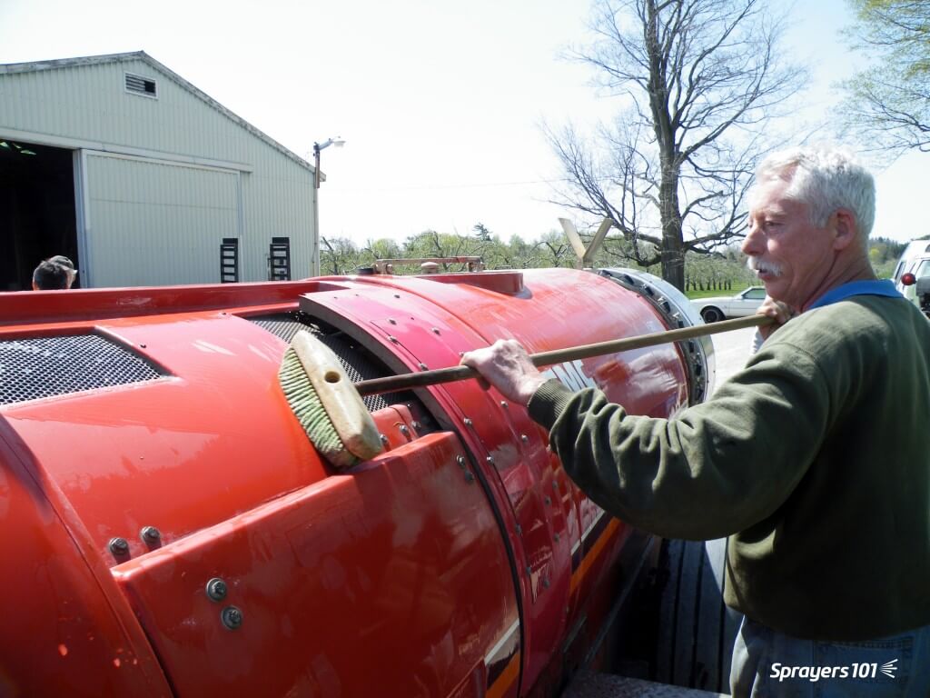
Six. Clean the exterior of the sprayer. High pressure washers and scrubbing with a push broom works well. Studies in Europe have shown the vast majority of residue is found on the sprayer head (i.e. fan outlet and boom area).
Pressure washers are handy tools on a farm, and they’re fun to use, too. However, they can cause a great deal of damage if they are used to wash delicate things like engine parts, electronics housings, or sealed bearings. Use caution when power washing an airblast sprayer.Relative external contamination on a low profile axial airblast sprayer. Image from Paolo Balsari’s (DiSAFA) “Sprayer Cleaning: Importance and Phases” at AAB Sprayer Cleaning Workshop, Oberbozen, Italy. October 2019.
Seven. Rinse it all off. Replace all parts unless preparing for long-term storage.
This article was co-developed by Mike Cowbrough, OMAFRA Weed Management Specialist in Field Crops
Why scrub filters?
Why do we ask you to manually scrub residue from sprayer filters and housings before changing chemistries? Here are three reasons why rinsing in-place may not be good enough:
There is potential for biologically-active levels of residue to persist in filters, even after a triple rinse, that could harm the next crop sprayed.
Persistent residues could cause physical antagonism with the chemistry you use next. This can cost time and/or efficacy should it plug filters and nozzles or reduce spray uniformity.
Persistent residues could cause chemical antagonism with the chemistry you use next – even several batches later. This could harm crops when the residue carried over from a much earlier application suddenly becomes soluble again thanks to detergents or pH adjusters in subsequent tank mixes.
An experiment
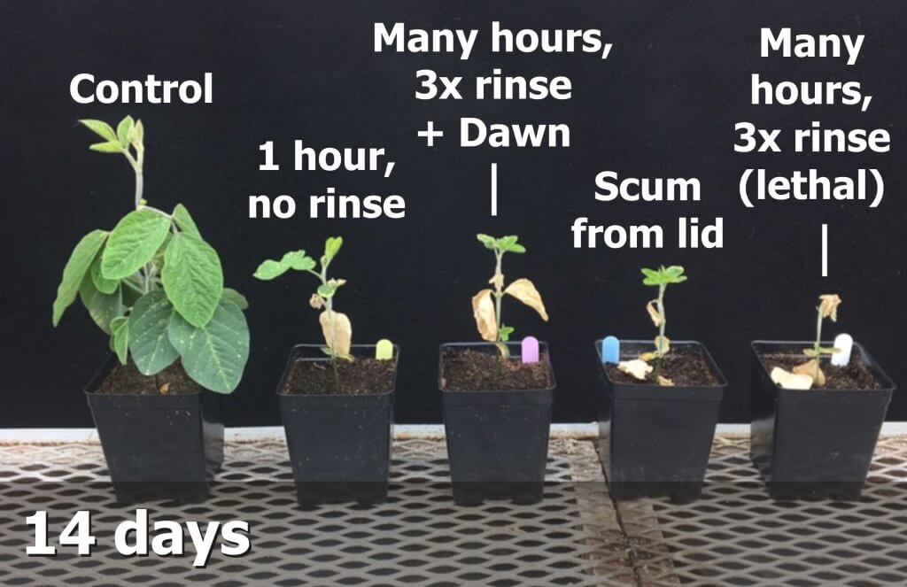
To some, the previous statements may seem excessive. Many sprayer operators claim that scrubbing filters is time consuming, or that they’ve never had a problem before, or that the tiny amount of residue they see in the filters after rinsing couldn’t possibly cause damage. We decided to test the efficacy of rinsing filters without removing them.
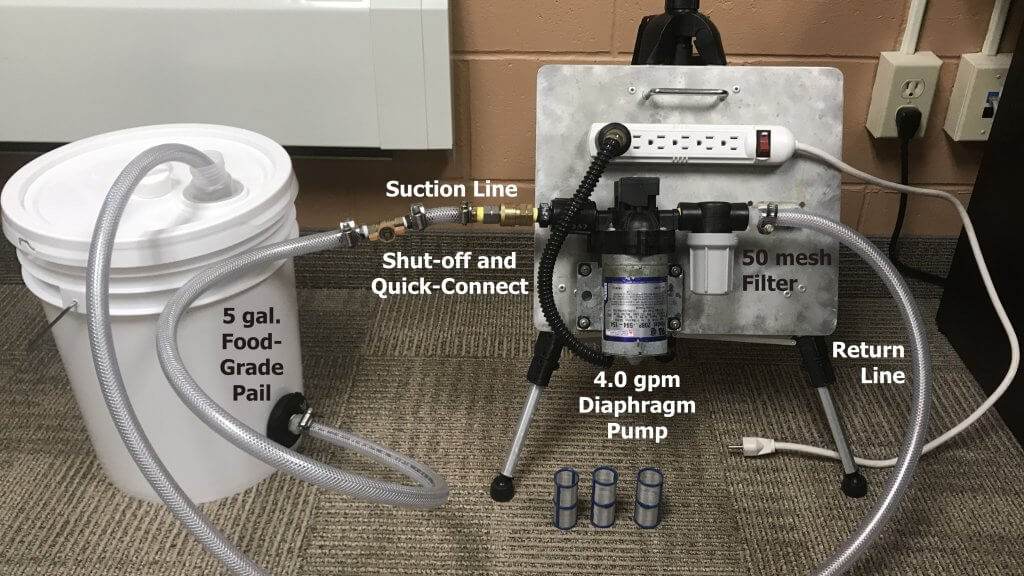
We constructed a table-top system that could circulate chemistry through a 50 mesh filter. Think of it as a scaled-down sprayer that returns solution to the tank rather than spray it out. It replicates what the line filters on a larger sprayer might experience during a typical spray day.
Table-top system to circulate spray mix at 1 gallon per minute through a 50 mesh filter.
The method
The tank (i.e. the bucket) would be filled with a tank mix and circulated through the filter to replicate a spray day. The contaminated filter could then be sampled to establish a baseline, and then alternately contaminated and rinsed in place to compare how much residue remained. Specifically, we would drop the filter housing and scrub all surfaces in 500 ml of water to collect any and all residue.
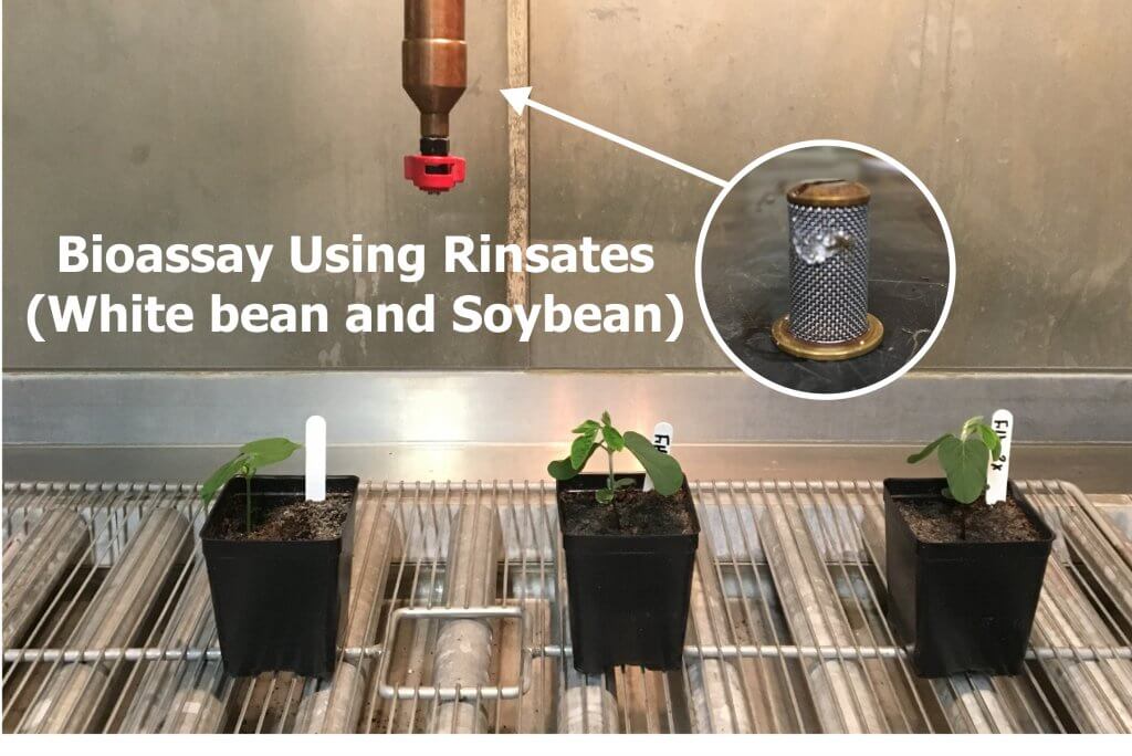
Each sample collected would be poured through a filter for a visual check of residue. A small volume would be reserved to be sprayed on soybean and white bean seedlings as a bio assay of activity.
The process
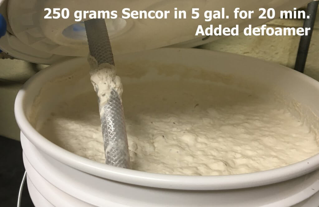
We used Sencor (metribuzin) mixed at a rate that represented the low end of the label: 250 grams of product per acre at 5 gallons per acre. Not knowing what to expect, we circulated the solution through the filter for 20 minutes pumped at a rate of 1 gallon per minute and peeked into the tank.
After 20 minutes of circulation, Sencor began to foam.
Seeing that we were creating foam, we decided to add defoamer. Then we peeked into the filter housing to see what had accumulated so far.
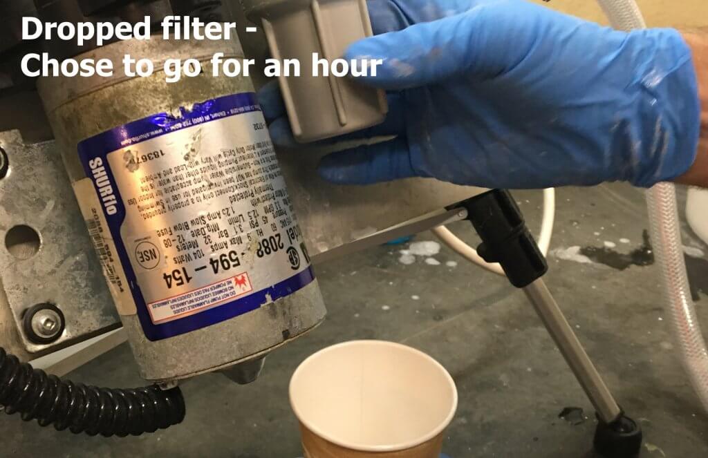
Very little residue was found on the filter or in the housing after 20 minutes of circulation.
Finding very little in the way of residue, we chose to let the system circulate for an hour. We felt this would represent a single real-world tank’s worth of product. Since we’d added defoamer, we decided it was safe to leave the lab and let the system circulate…
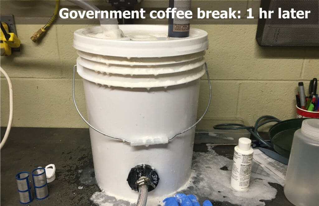
Foam overs: No fun in the field and no fun in the lab.
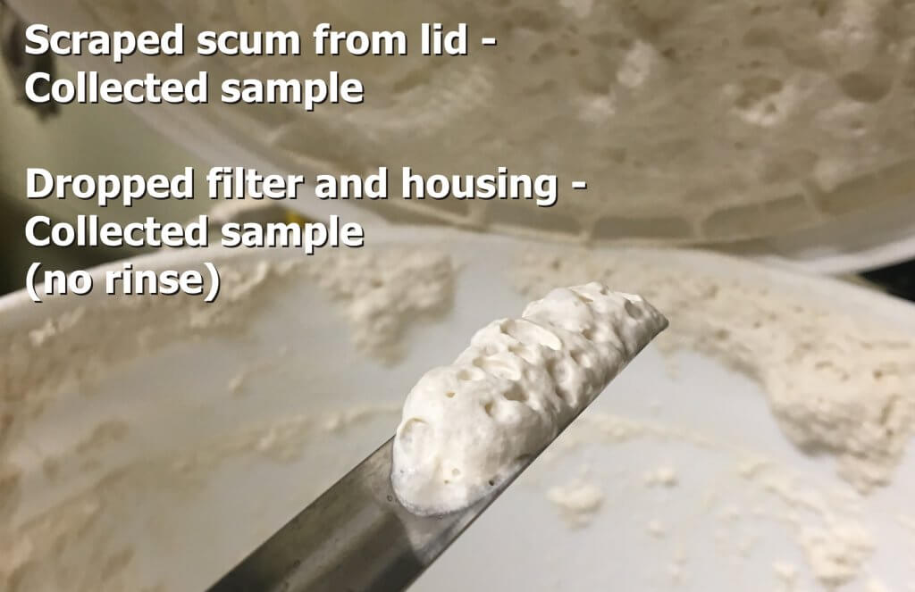
Despite having added defoamer, we had a mess to clean up. When we opened the bucket we noted all the product clinging to the lid (see below). We collected some of this scum to replicate what might be clinging to parts of the spray tank that are not adequately covered by rinse-down nozzles. We then dropped the filter into 500 ml of water and scrubbed the housing and filter to collect any and all residue.
Collecting residue from the bucket lid to replicate what might remain in a tank that is not sufficiently rinsed.
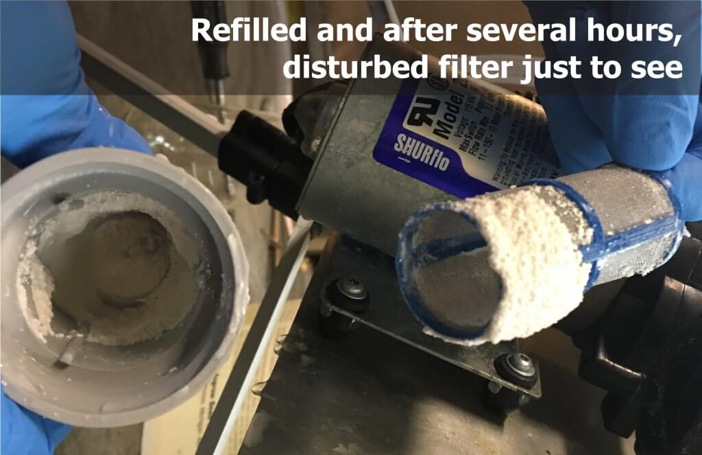
We then added additional defoamer and checked in regularly as we circulated the mixture for several hours to replicate a full day of spraying. This time when we checked to see how much residue we had collected, found a surprising amount.
Residue following several hours of circulation, prior to triple rinsing with water.
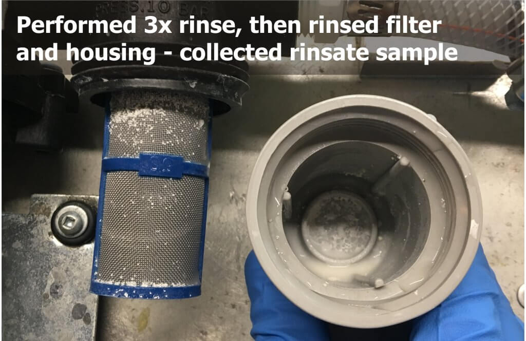
We replaced the filter and performed a triple rinse with water before dropping the filter to collect our residue sample. As shown below, the triple rinse cleared much of the residue, but trace amounts were still visible.
Residue following several hours of circulation and a triple rinse with water.
Dawn Detergent and the 5 Second Squeeze
We refilled the tank with Sencor and defoamer and circulated it for several hours to once again contaminate the filter. This time, however, we added detergent to the second rinse. We did this in response to claims that Dawn dish detergent removed residues from dry products such as Atrazine without having to drop the filters.
A former agrichemical rep explained that the practice likely originated in Western Canada some years ago when several growers suddenly experienced physical incompatibilities with a particular batch of dry product. It was suspected that the problem was due to abnormally cold temperatures during mixing, but the result was that many were left with solids in the tanks that could not be flushed.
Ionic surfactants are found in “cheap and nasty” shampoos, dish detergents and car care products. They can be tough on the skin, but they are of higher surfactantcy than NIS. And so, agrichemical reps bought pallets of Dawn dish detergent (Branded “Fairy” in the UK) from big box stores and found it broke the solids down sufficiently to flush the tanks. From there, it is likely growers started adding it during the rinse to facilitate cleanout. But, is the “Five second squeeze” a myth or does it work?
Results
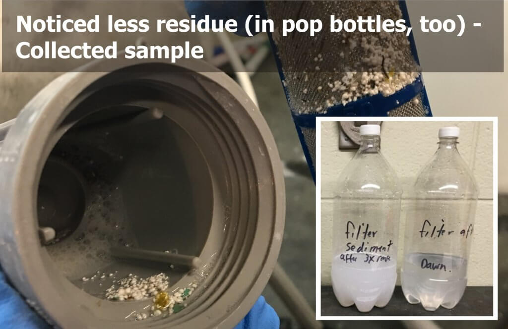
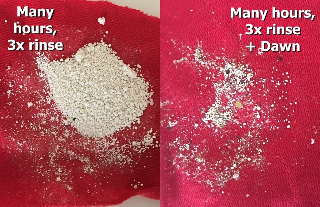
Adding Dawn detergent to the second rinse reduced visible residue in the filter housing and on the plastic sides of pop bottles that stored the rinsate.
We saw a visible reduction in the filmy residue left behind by Sencor in the filter housing and on the walls of the pop bottles used to store the rinsate. It was easy to see why the 5 second squeeze appeared to improve matters… but was there enough residue to still there to cause trouble?
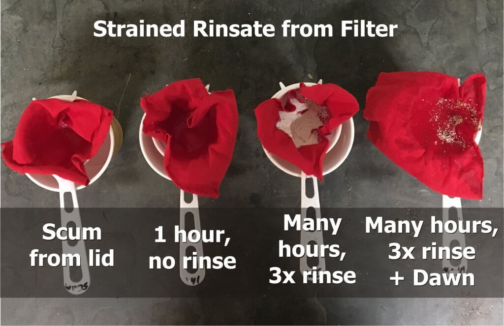
Rinsate filtered through red cloth for a visual check of residue.
We poured the rinsate from each sample through red cloth. There was little or no visible evidence of Sencor in the sample taken from the lid of the filter following an hour of spraying (left), or our baseline sample of a filter contaminated after an hour of circulation with no rinse (second from left). There was a great deal in the sample from the filter following “a day’s spraying” and a triple rinse (second from right), and less in the triple rinse containing detergent (right). These last two conditions are compared below.
Following several hours of spraying, residue following a triple rinse with water (left) and a triple rinse with detergent in the second rinse (right).
A volume of the rinsate from each sample was reserved for bio assay on soybean seedlings. The filter in the spray booth was cleaned thoroughly between conditions.
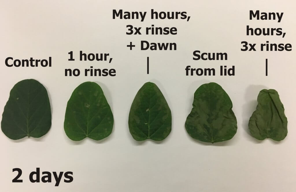
The following images show that even when there was little or no visible residue, there was still sufficient activity remaining to injure, or in the case of the triple rinse with water, kill soybean seedlings.
Summary
Bear in mind that this is a single experiment with a single chemistry, but it does support the following observations:
Always rinse the sprayer as soon as possible and pay attention to dead-end plumbing and filters. Diligence is a function of knowing what was sprayed last, what is coming next, and the sensitivity of the crops being sprayed.
Cleaners do not decontaminate – they loosen residues to make rinsing more effective. In our experiment, Dawn detergent appeared to reduce residue and that will keep you spraying plug-free for longer. But, the bioassay showed sufficient activity remained to cause carry-over damage.
A triple rinse with water may be insufficient to remove residue from filters. Even if the residue left behind does not cause damage in the next crop sprayed, it can persist and has the potential to react antagonistically with subsequent sprays.
Bonus: Pro Tips
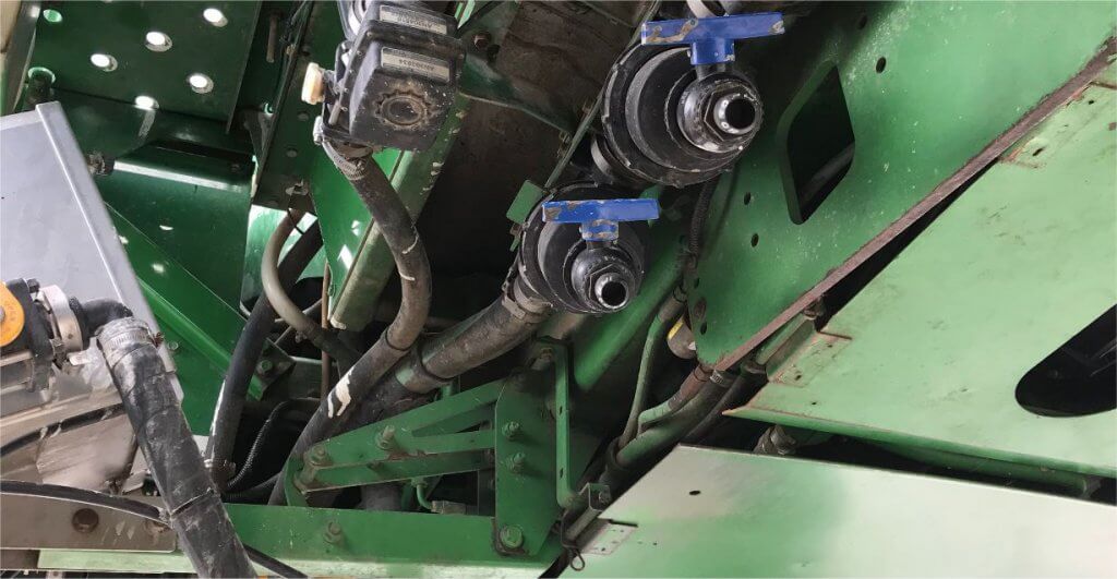
Not long after publishing this article, we were contacted by a grower who had difficulties with clay-based products plugging up his filters. It took a carry-over incident to convince him he needed to address the problem, so he installed $20 ball valves at the bottom of the filter housings. This isn’t as good as dropping and scrubbing filters, but opening and closing the valve under pressure during rinsing blew the filters clear of visible residue. Others have noted similar modifications on the pump of their tender truck to clear the filter of algae.
Other options include a hydraulic-style ball valve (stronger than plastic). Or, install a gator lock cam after the valve and insert a plug so if it’s accidentally opened it won’t dump the tank. Just keep a hose in the toolbox and insert it when you need to flush. Finally, one grower added a Thompson strainer to the sprayer and removed the screens from the Banjo Y’s. He ran a 1″ hose from the Thompson to a valve by the work station and cracks it open as part of every rinse.
A cheap and effective solution for clearing filters of residue. Not as good as dropping and scrubbing, but a great compromise.Ball valves tend to protrude below the sprayer, so they may catch high corn. Be careful.
Airblast sprayers are not rinsed as frequently or as diligently as field sprayers. This is primarily because they are not used to spray herbicides, so residue carry-over doesn’t incur an immediately obvious penalty. The typical operator rinses prior to long-term storage or when cross contamination might cause some form of antagonism (e.g. dormant oil followed by Captan or sulfur).
Learn more about the difference between rinsing and cleaning in this article.
Aftermarket Rinsing Systems
Airblast sprayers can be outfitted with rinsing systems that permit operators to rinse quickly, easily, and dispose of dilute rinsate in rotating locations.
A Serial Rinse (SR) system, common on field sprayers, re-purposes the pump to transfer clean water from a saddle tank to the product tank via tank rinse nozzles. The operator introduces a volume of clean water to the remaining volume in the tank, circulates it through the system, and then sprays the rinsate in the crop. Repeating this process three times (i.e. the Triple Rinse) serially dilutes the remainder, resulting in a higher dilution factor than a single high-volume rinse.
A Continuous Rinse (CR) system requires the addition of a dedicated rinse pump. In this case the operator introduces clean water to the tank via tank rinse nozzles while simultaneously spraying. While there is circulation from the bypass (and/or agitation) circuit, the remaining volume is diluted and essentially displaced by clean water.
Objective
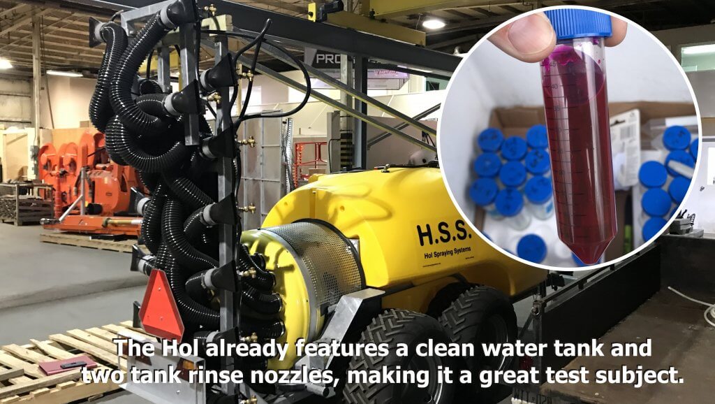
Using a fluorescent dye tracer as an analog for pesticide, we wanted to explore the effectiveness and efficiency of both systems. We describe the fluorimetry method in this article. We installed a CR system in a 2,000 L H.S.S. tower sprayer, which unlike most North American airblast sprayers, already features a SR system (150 L clean water tank and two tank rinse nozzles).
Installing a Continuous Rinse System
Installing a CR option required us to address the same three criteria we have already discussed in previous articles on field sprayer installs:
Identifying a CR pump with sufficient flow to operate the tank rinse nozzles
Satisfying the electrical or hydraulic requirements of the CR pump
Matching the supply flow from the CR pump to the demand flow at the booms
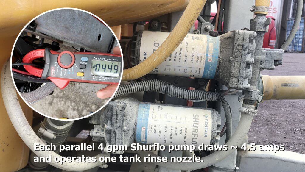
The Hol sprayer with an 18-nozzle ducted tower, 150 L clean water tank and two tank rinse nozzles. Inset: Rhodamine WT dye used as a pesticide analog for comparing residue levels.
We mounted two electric Shurflo pumps in parallel to provide flow sufficient to match the typical demand at the booms without excessive electrical load.
Parallel electric Shurflo pumps drew low amperage and provided sufficient flow to the boom.
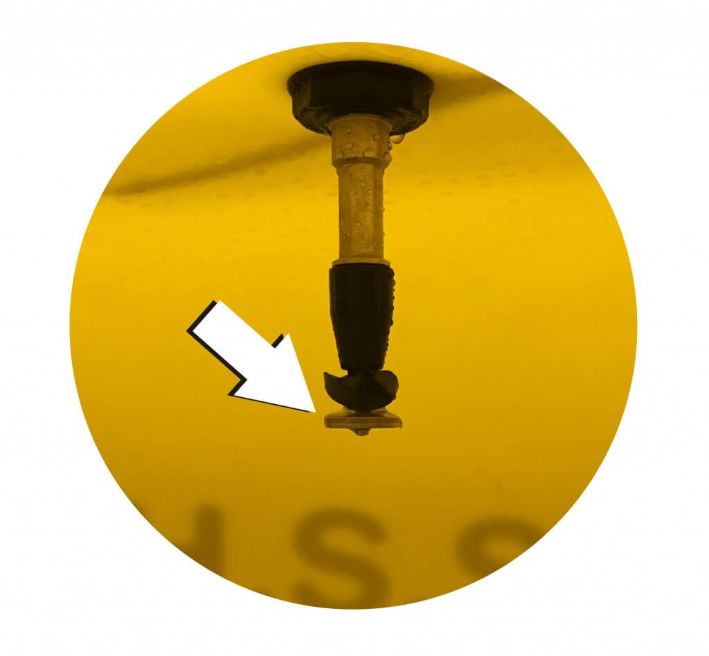
We found that while the CR flow spun the tank rinse nozzles weakly, the spray didn’t reach all interior surfaces. This was remedied by adding a deflector plate to the bottom of the nozzles to redirect flow.
A brass disc mounted on the tank rinse nozzle deflected spray to all interior surfaces.
We encountered a complication installing CR on an airblast sprayer compared to a field sprayer. Most field sprayers have rate controllers that permit the operator to adjust travel speed or ‘dial in’ a rate to match boom demand to CR pump supply. Unless the airblast sprayer already has this feature, the operator has to calculate in advance how best to match the flows.
The calculation has to be performed for each unique output (e.g. dilute or concentrate nozzle arrangements). The flow from the CR pump is a known constant. The nozzle output is variable according to operating pressure, calculated using a nozzle guide. The operator can adjust pressure (bypass or pressure regulator), PTO-speed (on positive displacement pumps), or even alternate between booms or boom-sections to match the flows.
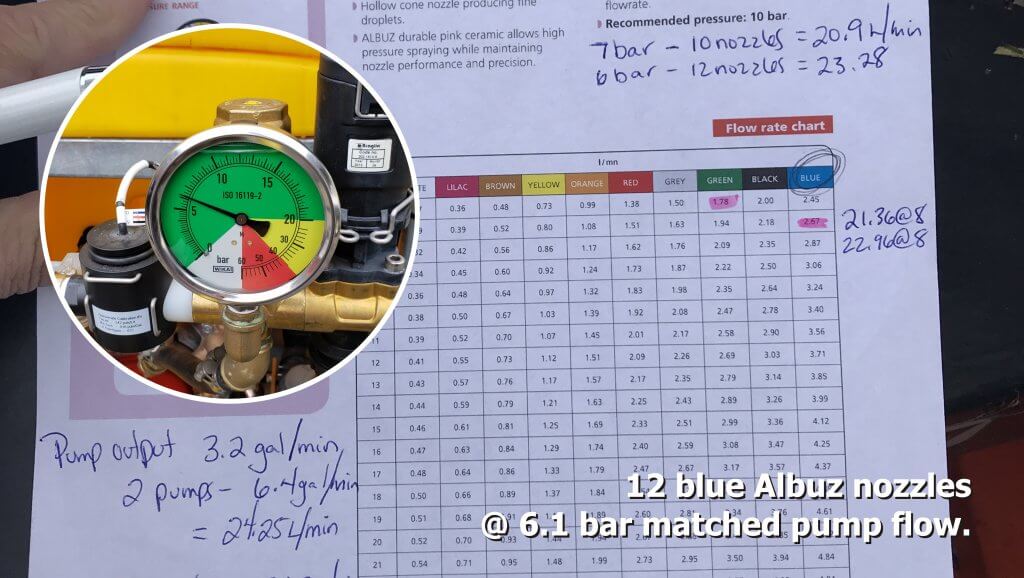
Matching flow demand to supply using a nozzle catalogue.
In our case, the operator was using 12 blue Albuz hollow cones in their orchard. We knew the CR pump output was 24.25 L/min. So, by setting the pressure to 6.1 bar prior to rinsing, we were spraying about 24.5 L/min. We parked the sprayer and watched to ensure the sump did not fill or drain during CR. Note in the following video how well the two flow rates were balanced (the camera was accidentally turned when we showed the vertical boom).
During trials we noticed that as the sprayer climbed uphill the water level in the tank shifted and the pump drew a little air, causing the nozzles to briefly sputter. This was a welcome sight given reports that introducing a few air bubbles during continuous rinsing can be beneficial.
Field Testing
During testing, we filled the 2,000 L Hol sprayer with 500 L of water and a final concentration of 0.25 ppm rhodamine (0.5 mL dye per 500 L water). The clean water tank was filled to 150 L. We allowed the mix to circulate for two minutes before priming the booms by spraying for a minute. A 50 mL sample was then drawn from the manifold (see below) and later used to represent the starting concentration during the analysis. The sprayer then drove through the orchard, spraying until empty.
Samples were drawn after the tank, before the manifold. Note the telltale Mancozeb coating the sprayer. PPE was worn.
Serial Rinse testing: When the sprayer was empty, the operator left the cab to introduce 75 L of clean water to the main tank via the tank wash nozzles. The rinsate was circulated for one minute before the operator returned to the cab and sprayed the orchard until empty. A 50 mL sample was drawn from the manifold to represent the concentration half-way through the rinse. The process was repeated for the remaining 75 L of clean water and a second 50 ml sample was drawn to represent the final concentration. We did this twice. It took about 12 minutes to rinse the sprayer and the operator had to leave the tractor cab twice.
Continuous Rinse testing: When the sprayer was empty, the operator stopped spraying and engaged the continuous rinse pump. After a few seconds, he continued driving and spraying rinsate. When 75 L had passed through the system, we paused to draw a 50 mL sample from the manifold to represent the concentration half-way through the rinse. The operator continued until the remaining 75 L was sprayed and a second 50 ml sample was drawn to represent the final concentration. We did this twice. It took about 5 minutes, 45 seconds to rinse the sprayer and the operator did not leave the tractor cab.
Sample Analysis: A Turner TD 700 fluorometer was calibrated using samples from the tank. Samples were diluted when necessary to ensure they fell in range of the calibration curve (where there is a linear relationship between the concentration of Rhodamine WT and Raw Fluorescence Units (FSU)). This range spanned a maximum of 0.1 ppm and a detection limit of 0.01 ppm active ingredient. Having previously tested recovery accuracy of 95%, data was adjusted accordingly.
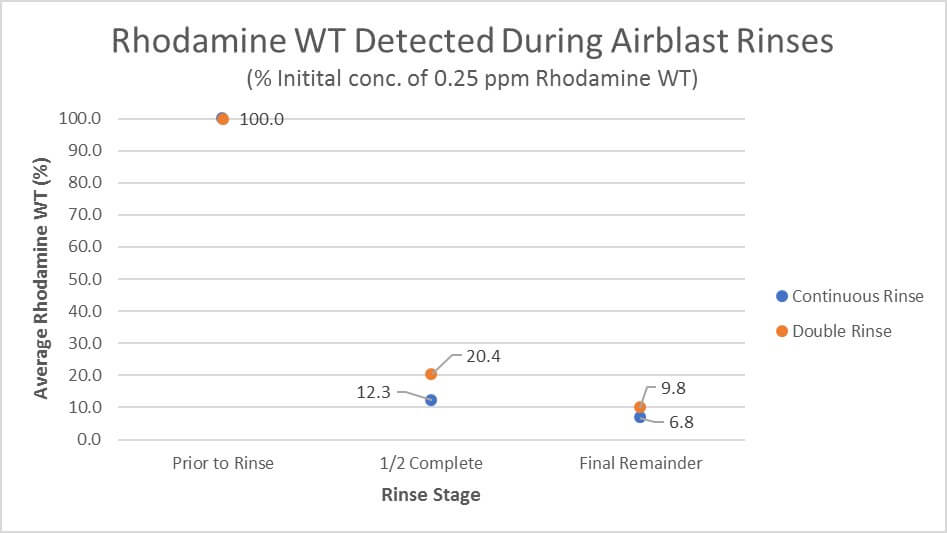
Results of rinsate analysis. n=2.
Observations
While both methods diluted the residue significantly, the remainder following both Serial and Continuous Rinse was much higher than anticipated. This may be an artifact given that both concentrations are potentially below our detection limit, per the following:
Assuming 10 L of residual spray volume left in the system once “empty”, 75 L added would give a dilution factor of 9 (according to the ). While the first 75 L of Continuous Rinse seems to remove more residue than a single addition of 75 L, both are higher than anticipated. A subsequent addition of 75 L should result in a dilution factor of 72. In this case, the remainder would be below our fluorometer’s detection limit, and could explain the results.
Nevertheless, there were positive observations:
Continuous Rinse resulted in a more dilute rinsate with less water than Serial Rinse.
Continuous Rinse took less time than Serial Rinse.
The operator did not leave the tractor cab during Continuous Rinse.
Potentially, any remaining water from the Continuous Rinse system could be used to operate a spray wand to rinse the sprayer exterior before leaving the crop.
Both systems encourage improved airblast sprayer sanitation and reduce environmental impact from point source contamination.
Thanks to ProvideAgro for performing the installation, Wilmot Orchards in Ontario for supplying the sprayer and running the trials, and OMAFRA summer student Aidan Morgan for assistance with the data analysis.
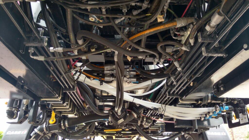
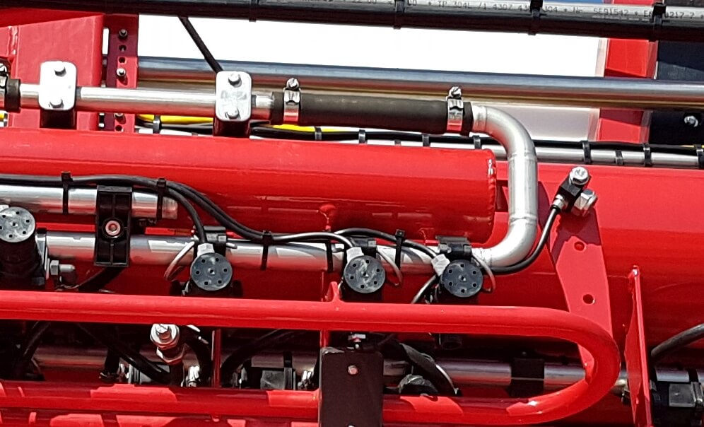
A lot of people are intimidated by sprayer plumbing. One look at the spaghetti bowl of spray mix and hydraulic hoses and valves, and they walk away. It hasn’t helped that much of it is concealed under the frame and all of it is in the same black colour, so figuring it out on your own is almost impossible.
Belly of a typical sprayer, showing black hydraulic and spray hoses.
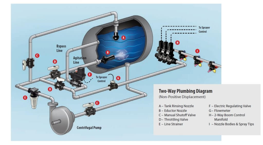
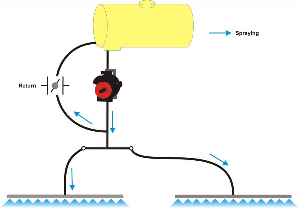
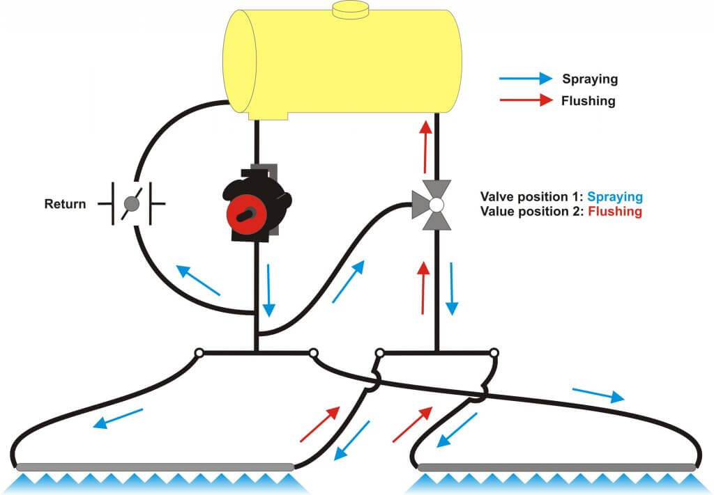
Let’s quickly review the basics. In all sprayers, the liquid in the tank is drawn out from the bottom and pressurized by a pump. The pressurized liquid is split into two main paths. One goes to the spray boom to hydraulic atomizers (nozzles). The other goes back to the tank to agitate the liquid and act as a pressure bypass when the booms are off. Bypass throttling changes pressure. That’s it.
Sprayer plumbing diagram (Source: TeeJet).
By the way, has anyone ever thought of some colour-coding or labelling the hoses and valves on a sprayer? We’d definitely appreciate that.
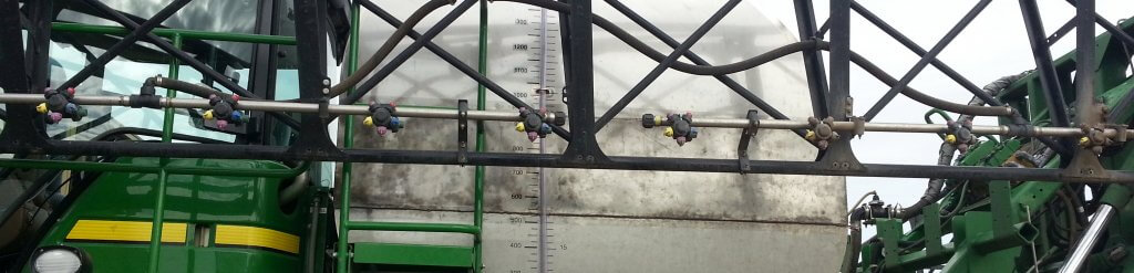
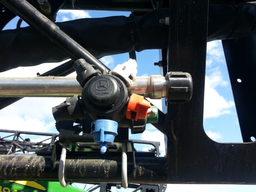
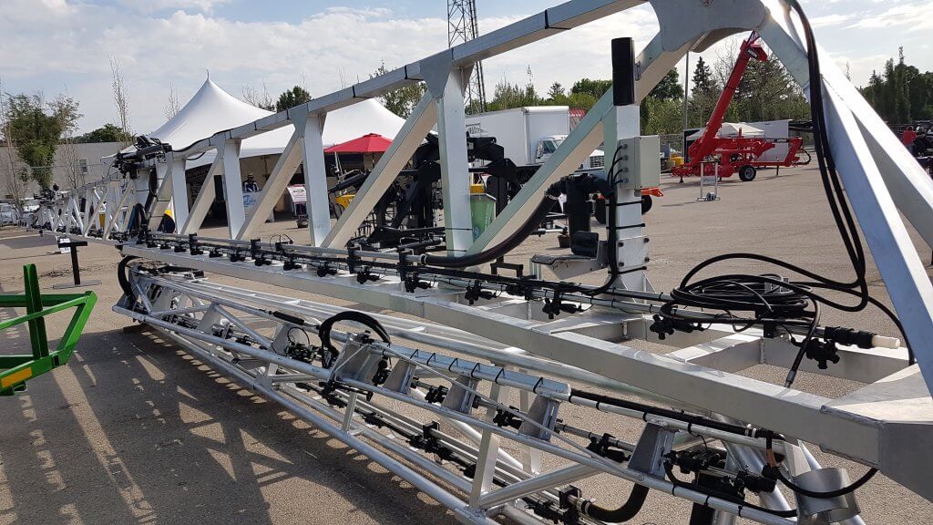
Conventional boom sections
Most North-American sprayers feed the pressurized liquid to the boom, where the flow is subdivided into physical sections that define the various portions of the boom that can spray at any one time. Older sprayers might only have two sections, the left and the right boom. Wide booms now have anywhere from 5 to 13 sections, each about two to four metres wide. Each section has a pressure feed to its middle, and each section terminates at two dead ends, at which we place caps or valves for flushing.
A conventional plumbed boom with two sections. Each section has two terminal ends that require cleaning. Boom can only be flushed or primed by spraying or by opening boom end caps.
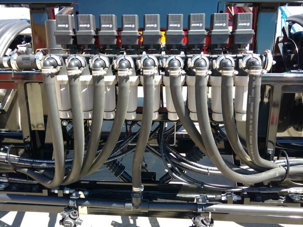
Sprayer with nine sections, each controlled by its own valve and each running a dedicated feed hose.
Two partial boom sections, each showing a central feed line and a capped boom end.
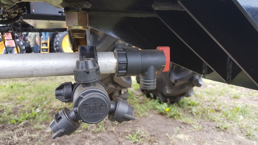
Sectional boom end showing 10 cm of capped pipe beyond last nozzle body.
Boom end with valve to facilitate draining and flushing.
Any liquid that enters this type of boom must exit at the nozzle or the boom end. It must be sprayed out or drained. This poses three distinct problems.
If the boom contains water or a previous spray mix, the boom needs to be primed with the new product before spraying. We need to spray or drain the existing product out.
If we want to clean the boom or flush it with water, again we need to push the existing liquid out.
If we have dead spots in the boom section, such as a boom end, we need to take special care to flush those out as well.
These characteristics complicate cleaning, create waste or contamination, and take time.
Recirculating booms
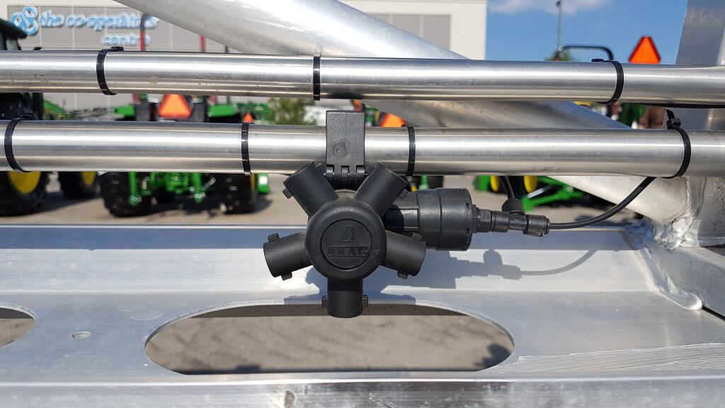
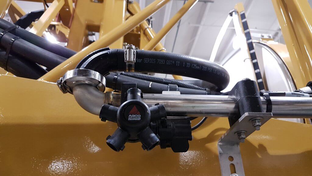
In a recirculating boom, the spray mixture enters the boom at one end and exits at the other, returning to the spray tank. In most cases, the left and right wing each has its own feed and return. Sectional control is achieved via individual valves (air or electric) placed on the nozzle bodies.
There are two main types of recirculating booms on the market.
The first system routes the pressurized mixture into the boom and shuts off the return line during spraying. When the nozzles are shut off for a turn, the return line opens automatically and the boom flow is pushed past the nozzles back to the tank. When the nozzles spray again, the return line closes to pressurize the boom.
Recirculating boom system offered by Pommier. One end of boom is pressurized, the other end is return. Return flows when boom spraying is shut off. Boom can be primed or flushed without spraying.
This is the system used by Pommier, the French aluminum boom manufacturer who first introduced recirculating booms to North America.
Pommier recirculating boom.
Pommier boom showing stainless steel supply and return lines, as well as air-activated shutoff valve on nozzle body.
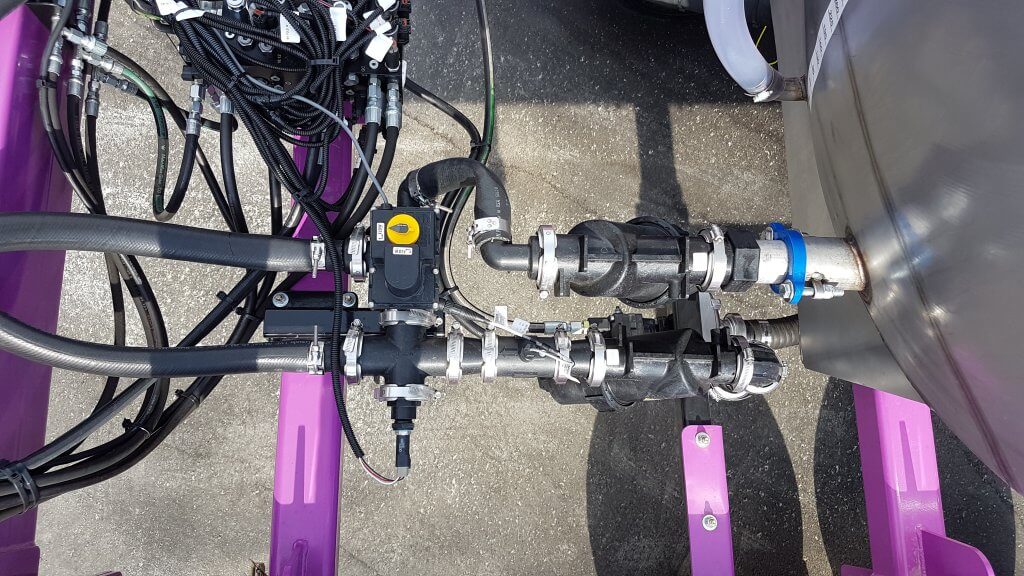
The second type of system contains a 3-way valve, connected to the return line and the pressure side of the pump. This valve provides the option of either allowing the return line to go back to the tank, as above, or to also allow pumped flow to the return side so that the boom is pressurized at both ends.
Recirculating boom that allows return line to be either pressurized by pump, or return to tank.
Top view of D.O.T. Connect sprayer recirculating boom setup. Lower line is pressurized by pump. Upper line is return. Three-way valve allows return line to either go back to tank, or be pressurized by pump.
Tidy setup of pressure and return lines on D.O.T. Connect system.
This feature may be useful with long booms along which pressure drop is more likely to occur, or when very high flows are required, and was introduced to North America by the Dutch manufacturer Agrifac, about which we wrote here and reprinted Mick Robert’s article from Pro Operator here. A similar system is available from Rogator (starting in 2018) via their C-Series featuring LiquidLogic. It has also been used on the Connect sprayer, developed by Pattison Liquid Systems, for the D.O.T. autonomous platform.
The main advantages of this design are that it provides the option of additional pressure to the spray boom to avoid pressure drop, and to allow any spray mix in the return line to be pushed and sprayed out to the boom for rinsing in the field. This lowers the remaining volume that needs to be diluted.
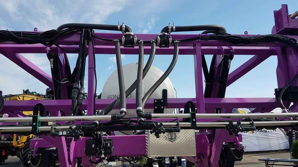
Agrifac recirculating boom showing return loop at boom end.
Boom end on Rogator Liquid Logic system. Note Hypro Pro-Stop E shutoff valve.
Features
Recirculating booms offer advantages in terms of preventing soil and water contamination and also in terms of simplifying the boom cleaning process. The design provides an opportunity to graduate to a better resolved sectional control as well due to the requirement for individual nozzle shutoff valves.
Due to shorter and less complex lengths of plumbing needed, stainless steel can be used for the return lines which decreases the potential for pesticide residue being adsorbed.
To rinse a boom with product mix still in the tank, simply draw water from the on-board clean water tank and push it to the boom without activating any nozzle bodies. The mix in the boom is returned to the tank and replaced with water, nothing is sprayed or drained. The tank contents may become slightly diluted depending on the duration of the rinse.
To rinse the tank as part of the sprayer cleanout, first spray the tank empty. Then introduce clean water into the product tank via the wash-down nozzles and spray that out. As always, either use several batches of small clean water volumes, or a continuous rinse system, to dilute the remainder most effectively. There may be additional volume to dilute from the return lines compared to a conventional system, depending on the type of recirculating system is used. However, boom ends no longer exist and this saves effort and ensures a more thorough rinsing.
To prime a boom that contains water, simply open the return lines back to the tank and allow the new mix to flow through the boom. Again, some dilution of the tank will occur due to the water in the boom.
The value of spray-free rinsing and priming adds up. Each prime, for example, consumes about 30 US gallons before the spray reaches the last nozzle of the longest section. Much of that product ends up on the ground, probably while the sprayer is stationary, and probably in a similar place on the field year after year.
Since a recirculating boom requires a powered individual nozzle shutoff, this adds some cost. However, the opportunity of improved sectional control via virtual sections is significant (most monitors offer 16 virtual sections that can be configured). Well-configured virtual sections can save several percent from overlaps.
Recirculating booms remove many of the contamination problems associated with conventional plumbed sections. They save time, money, and reduce environmental impact. We think they should be offered on sprayers.
Here’s a link to a nice article on recirculating booms written by Spencer Myers for the Manitoba Co-operator. A video that goes with the article can be found here.