In 1977, David Shelton and Kenneth Von Bargen (University of Nebraska) published an article called “10-1977 CC279 Gear Up – Throttle Down”. It described the merits of reducing tractor rpm’s for trailed implements that didn’t need 540 rpm to operate. In 2001 (republished in 2009), Robert Grisso (Extension Engineer with Virginia Cooperative Extension) described the same fuel-saving practice. Again, it was noted that many PTO-driven farm implements don’t need full tractor power, so why waste the fuel? He tested shifting to a higher tractor gear and slowing engine speed to maintain the desired ground speed. 700 diesel tractors were tested, and as long as the equipment could operate at a lower PTO speed and the tractor itself didn’t lug (i.e. overload), as much as 40% of the diesel was saved.
How this applies to Airblast
For airblast operators with PTO-driven sprayers and positive-displacement pumps, this has potential for reducing air energy. Gearing up and throttling down (GUTD) sees the operator reducing the PTO speed from 540 rpm to somewhere between 350-375 rpms, which not only saves fuel but more importantly slows the fan speed. This may be an option when air energy from the sprayer, even at higher travel speeds and a low fan gear, still overblows the target canopy.
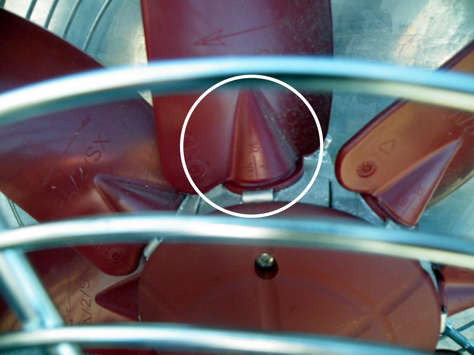
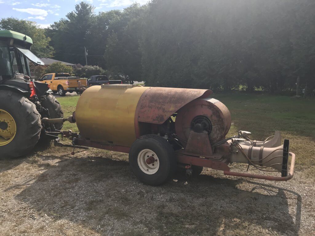
Some airblast sprayers, like this one, feature fan blades with manually-adjustable pitch to increase or lower air volume and speed. It’s often a pain to try to adjust them, and most operators only try it once.
A good time to try this out is early in the spraying season when (most) canopies are dormant and at their most sparse. For example, when applying dormant sprays in apple orchards, look to see if the wood on the sprayer-side gets wet, but does not creep around the sides. This suggests that the air, and much of it’s droplet payload, are being deflected. When the air speed is slowed, it will become more diffuse and turbulent on target surfaces, and this turbulence helps more droplets deposit in a panoramic fashion within (not past) the target canopy. Look to see if the wood is wet >50% around the circumference of the branches. You’ll get the rest when you spray form the other side.
Limitations
GUTD is not always appropriate. It requires airblast sprayers with PTO-driven positive displacement pumps (e.g. diaphragm). Airblast sprayers with centrifugal pumps would experience a drop in operating pressure and would have to be re-nozzled. Further, the pump must have sufficient surplus capacity to maintain pressure at low rpms.
GUTD is not intended for air-shear sprayers that employ twin-fluid nozzles because dropping air speed below a certain threshold may compromise spray quality; the air needs to be fast enough to create and direct spray droplets
The tractor must have sufficient horsepower (more than 25% in excess of minimally-required capacity) to permit the reduction in engine torque. This is especially important if the operator is on hilly terrain. If the tractor begins to lug (e.g. black smoke, sluggish response, strange sounds) you’ll be in trouble.
Observations
We first experimented with GUTD in 2013. We noticed how much quieter the sprayer was, and the fuel consumption was certainly reduced. One grower-cooperator switched to a GUTD spray strategy mid-way through their dormant oil application in pears. We saw the trees immediately began to drip. Panoramic coverage was improved significantly; once the operator passed down the other side of the target, capillary action and surface tension helped to give near-complete coverage.
However, in one instance, the operator was already applying a low spray volume per hectare using air induction nozzles and their lowest fan gear. By further slowing fan speed using GUTD, coverage at the top of his cherry trees was compromised.
In short, GUTD can work under the right circumstances. If you want to try it, use water-sensitive paper to establish a base-line with your current practice, and then evaluate coverage after you change your sprayer settings.
We’ve identified and discussed shortcomings in the content and design of today’s pesticide labels in an earlier article. From the perspective of the spray applicator, the information needed most often can be difficult to locate, anachronistic, contradictory, subjective or even missing from the label altogether. To truly encourage an applicator to read and follow the label we need a consistent, concise and clear format that summarizes critical content.
To that end, we have worked with growers, university/government extension and industry to develop a prototype we’re calling the “Label Summary Sheet”, or LSS for short. We presented the concept in a series of public presentations in western Canada as part of the RealAgriculture TechTour Live event in 2018. You can watch a recording of part of that event at the end of this article.
The LSS does not replace or interpret the current label, which is a legal document. It is a summary intended to accompany it. At this stage the LSS is simply a proposal. These documents are not intended for use right now; we hope they will grow and change for the better as they stimulate discussion.
Consider this metaphor: You have just purchased a laptop. When you unbox it, you get an in-depth instruction guide that covers everything from operation to trouble shooting and includes all the legal riders. It’s a daunting technical document that you likely won’t read unless something goes wrong. Knowing that, manufacturers include a graphic and accessible quick start-up guide that summarizes the most common and critical issues. It doesn’t replace the instruction manual, it just augments it. If you can’t find what you need in the quick start-up guide, you are referred to the more fulsome description in the instruction manual. Think of the pesticide label as the instruction manual and the LSS as the quick start-up guide.
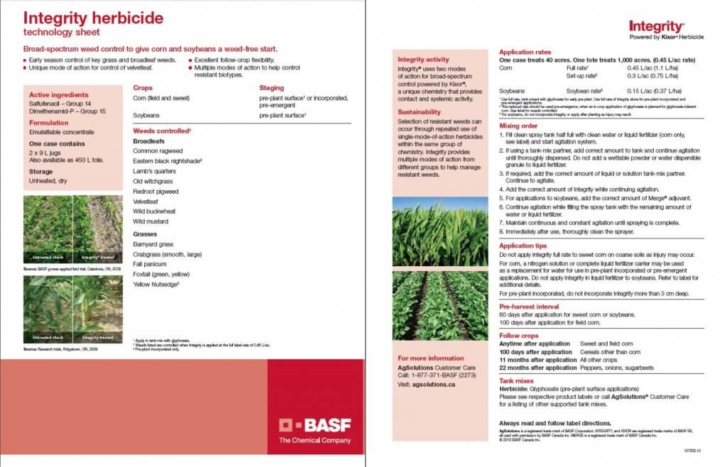
Some agrichemcial companies recognize this need and have developed short documents to summarize key aspects of the label, but they are inconsistent and brand-specific marketing documents that do not always contain the information we are proposing. Here, for example, is the technology sheet for Integrity herbicide.
We tested the versatility of our LSS format by summarizing four diverse pesticide labels. Our selections are not intended to imply that these labels are particularly deficient. Only that they are commonly used, somewhat complicated and represent the spectrum of pesticide categories and application methods.
Download and look at the variety of labels we have summarized as examples. They are available here:
Note that each LSS features the same section headings and a relatively consistent layout, no matter the manufacturer. Generic icons are used to illustrate content and make it easier for users to navigate without language barriers. The LSS are black and white to facilitate reproduction and refer back to their respective pesticide labels (i.e. the online PDF, not the booklets that come with the pesticides).
LSS Sections
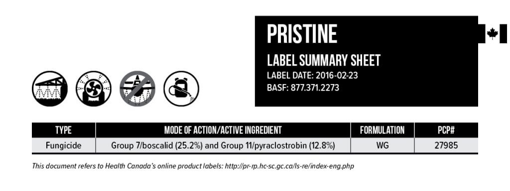
Here is the Pristine LSS broken down by section to highlight the key features.
1. Banner Section
The banner is at the top of every LSS. It gives the commercial product name and the date to ensure the LSS reflects the current pesticide label. Four icons represent the most common application technologies: Horizontal boom sprayer, airblast, aerial and handheld. If an application method is prohibited, a banned symbol appears (such as aerial in this case). Note we have left room for RPAAS (UAV’s) anticipating the day we have products registered for that technology. The table notes the type of pesticide (e.g. fungicide, insecticide, adjuvant, etc.). The mode of action and active ingredient(s) are noted, as well as the formulation and the Pest Control Product number.
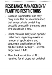
2. Resistance Management / Planting Restrictions
Intended to provide key information on managing pesticide resistance, this section reflects label content about carry over and the rotation of active ingredients. Further, to aid in application decisions, it reflects any restrictions around maximum number of applications, sequential applications or plant back issues following use.
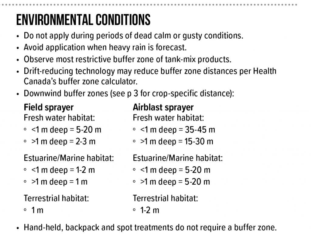
3. Environmental Conditions
Any restrictions regarding weather conditions during or after application are noted here. This includes set-backs or buffer zones that reflect method of application and the nature of the adjacent or downwind area in question.
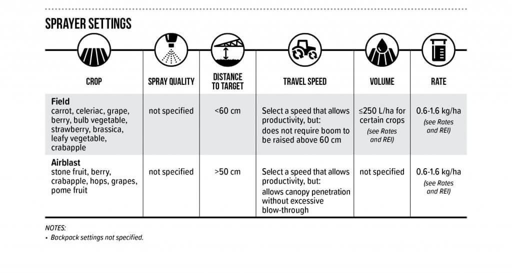
4. Sprayer Settings
This section includes the six most commonly asked questions an applicator has when calibrating or adjusting their sprayer prior to use. It is organized by target crop and method of application. When the label provides a high level of detail, the user is referred to the correct page. Note the use of graphics to quickly direct the reader to the information they need. Any additional qualifications found in the label relating to sprayer settings are indicated in the notes beneath the table.
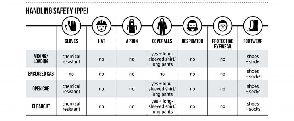
5. Handling Safety (PPE)
The concept for this simple and graphic table originated in France, and was communicated to us by Dr. Carol Black of Washington State University. This unambiguous format encourages the use of PPE while ensuring the handler uses the appropriate level of protection for each activity.
6. Mixing
As operators tank mix more products to curtail resistance, improve efficacy or improve productivity, there is a greater chance of chemical or physical incompatibility. This section summarizes any restrictions noted in the label. Learn more by downloading Purdue Universities’ publication “Avoid Tank Mixing Errors“.
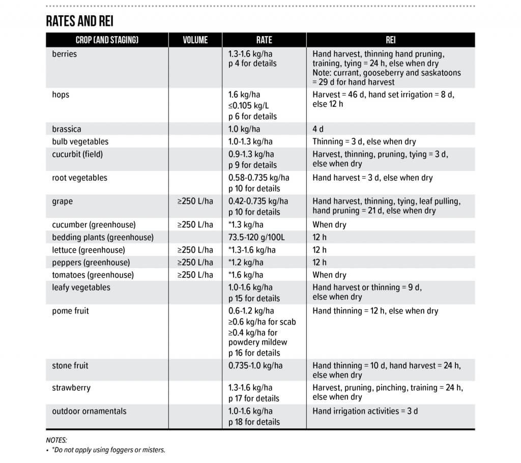
7. Rates and Restricted Entry Intervals
This table can be quite complicated depending on the pesticide label. It summarizes the rates, volumes and restricted entry intervals by crop. It reflects the broadest range of product rates listed in the label. Restricted entry duration is affected by the post application activity, and this is captured in the REI column. If more detail is required, the user is referred to the appropriate page(s) of the label. Any additional qualifications found in the label relating to rates, volumes or REI are indicated in the notes beneath the table.
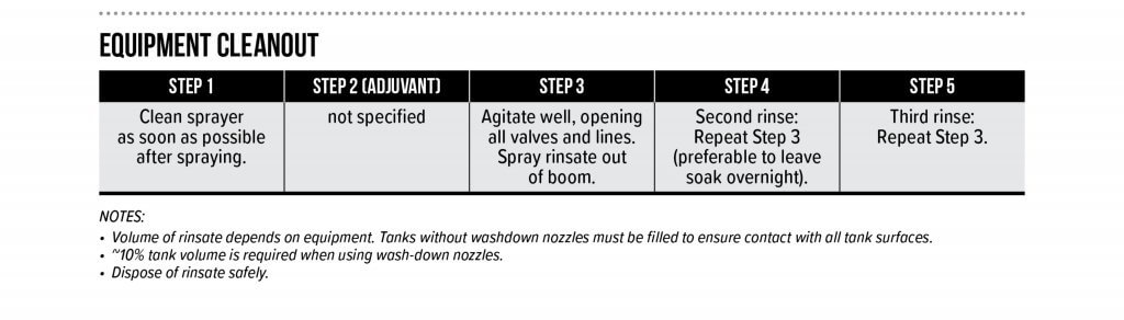
8. Equipment Cleanout
Finally, equipment cleanout is summarized (where possible) in a sequence of steps. When the pesticide label is silent on the cleanout procedure, the user is provided with the triple rinse protocol, which is generally held to be the industry best-practice.
Adoption
To date, this proposal has been made to Croplife Canada, the American Society of Agricultural and Biological Engineers (ASABE), an International Organization for Standardization (ISO) mirror committee (Equipment for crop protection) and more than 1,400 growers and stakeholders across Canada.
Our suggestion for adoption of the LSS (in its current form or something similar) is that regulatory agencies commission a working group comprised of representatives from grower groups, industry and government to oversee the process. The working group would support registrants as they populate (or update) the LSS template when a new product is submitted for registration, or as part of the natural review cycle.
Should the registrant encounter duplicate, missing or contradictory information while completing the LSS, it should be considered an opportunity to remedy the problem on the pesticide label. This will clarify the safest and most effective use of the pesticide for the applicator, who is currently forced to selectively ignore or interpret such errors. To our minds, this was the intent of the original labelling system, and the inclusion of the LSS is a simple and effective way to achieve that goal.
The Confusicol Sketch
In 2018 we participated in Real Agriculture’s TechTour Live event that toured four major cities in Western Canada in four days. We presented the “Confusicol sketch” as a light-hearted way to open a discussion with the audience on the strengths and weaknesses of Canadian pesticide labels and how the Label Summary Sheet might be a viable supplement. Here’s one of the live takes, warts and all. Turns out live sketch comedy is tricky…
Harvest is mostly done and growers want to hear what we’ve learned and what’s coming next. Lecture season is upon us once again.
In 2021 we’re still finding our way through virtual conferences and hybrid models, but I like to think we’re slowly returning to the in-person format. Just last week I gave my first in-person talk in 20 months. It felt wonderful after having spoken into a dead-eyed camera for so long. Half-way through my lecture I remembered a lesson I learned a few years back and spontaneously decided to go off-script.
Let me explain.
In 2016 I was invited to present at the 40th annual Tomato Days conference in Southern Ontario. I knew what I wanted to say, but didn’t have a decent slide deck for that particular topic. I’d have to pull one together.
I work hard on my presentations. I employ lots of imagery (I create all my own illustrations). I get persnickety about fonts, white space and slide transitions. I try to tell a story that educates and hopefully, entertains. Prideful? Perhaps. But if you’re willing to sit on a hard chair for an hour, I’m going to do my best to make it worth your while.
I finished the slide deck, drove three hours to the conference, handed my USB data key to the organizers and sat down to wait my turn. It was a clear, bright winter morning and I saw that the pavilion we were in was more-or-less windows and a roof. It was so bright, in fact, that none of the 150 attendees could see the projector screen!
I watched sympathetically as the first speaker spent 30 minutes trying (and failing) to verbally describe his graphs. I cringed as the second speaker pantomimed her illustrations in some kind of brave, interpretive dance. Then it was my turn.
I decided I wasn’t going down that road.
When the moderator brought up my talk, I turned the useless projector off. I asked the squirming and disinterested audience:
Q. “What’s the most terrifying thing you can do to an academician?” A. “Take their Power Point away.”
For the next 30 minutes we had a discussion about spray coverage. No props. No slides. The audience slowly warmed up to the new format. They shared experiences. They debated. They asked questions. I became more facilitator than speaker.
When our time was up I think everyone was pleased. Sure, I missed a lot of my key points and never really addressed the subjects I thought I would, but who cares? Everyone learned something.
For me, I learned that speakers should abandon the script every now and again. It’s not always ideal since we’re there to teach and structured visuals are often required. But, the next time you’re asked to speak, consider the possibility of using your time to engage your audience and establish a dialogue… not just talk at them until the moderator gives you the 5-minute warning.
I have a colleague who does this masterfully. Whenever he is the last speaker on the agenda, and the previous speakers have discourteously gone over-time and whittled his time in half, he jumps straight to his take-home slide. He leads a quick discussion with the audience and becomes a hero. The moderators are now back on schedule and no one is late for lunch.
Since “Tomato Days”, I now try to do this once a year. I never know when the mood will take me, but when it does I give the audience a choice: They can hear my canned presentation or I can shut it down and we can have a conversation. To date, given the option, every audience has opted to go off script. It’s scary, it’s fun and like I said earlier, everyone learns something.
I challenge you to try it the next time you’re lucky enough to be in front of an audience in person.
Press Play to hear the audio version of this article
Adjusting Sprayer Settings
Operators are encouraged to adjust airblast sprayer settings to conform to the variability in canopy size, density, spacing, and weather conditions. The efficiency and accuracy of the application is improved through the regular and independent adjustment of travel speed, nozzle output, and air settings.
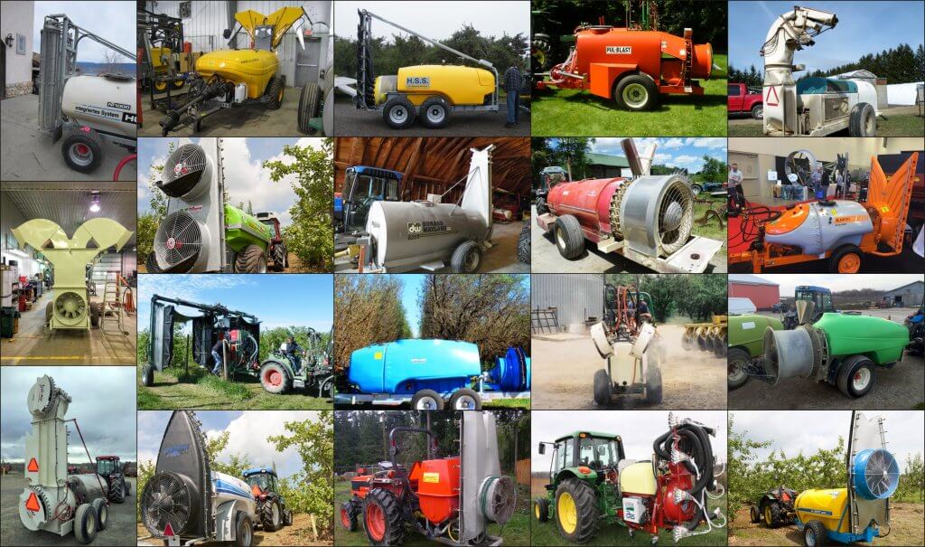
Airblast design is highly variable.
Inflexible sprayer design results in a suboptimal match between equipment and crop. For example, sprayers intended to blow across multiple rows in a single pass are promoted for their high productivity, but typically compromise either coverage uniformity or drift control. In another example, low volume mist blowers utilize high speed air to atomize spray and are promoted as a means for saving water and/or pesticide. But, for many such sprayers, moderating air speed to reduce drift potential causes undesired changes to spray quality.
Even with geared fans, many of Ontario’s airblast sprayers are overpowered for vines, canes, bushberries and high-density orchards. I am uncomfortable with manually obstructing the air intake or adjusting fan blade pitch for safety reasons. Fan gears and travel speed are excellent means for adjusting air energy. Alternately, we have sometimes had success reducing air energy by gearing the tractor up and throttling down (GUTD), but it’s only for very specific situations.
It has been my experience that centrifugal pumps on axial airblast sprayers can undermine adjustment efforts when spraying small to medium sized canopies (i.e. not tree nut or citrus). In the case of GUTD, slowing the fan reduces pressure at the nozzle. Modest pressure regulation may be possible, but typically the operator must swap to larger nozzles to maintain flow. Hollow cone nozzles are only available in large flow increments (average 0.5 gpm), and stepping-up often results in excessive flow. The operator may be able to increase travel speed to compensate, but this frustrates the original intention by affecting dwell time: air settings must now be reconsidered.
Within this context, why do some Ontario airblast operators still choose airblast sprayers with centrifugal pumps? Let’s consider Ontario’s Georgian Bay area, which many manufacturers, distributors and mechanics refer to as “the last bastion of the centrifugal pump in Canada”.
Remember as you read on, Ontario’s airblast crops are predominantly small to moderate sized canopies. Centrifugal pumps are a common and appropriate pump for large canopies like tree nut and citrus.
Airblast Pumps (in Ontario)
The Georgian Bay region of Ontario.
Airblast sprayer design is highly variable, featuring a diversity of pump styles. Piston (or plunger), peristaltic, tractor-hydraulic driven centrifugal pumps are but a few. Historically, piston pumps and centrifugal pumps on John Bean and FMC sprayers were the airblast norm in Canada.
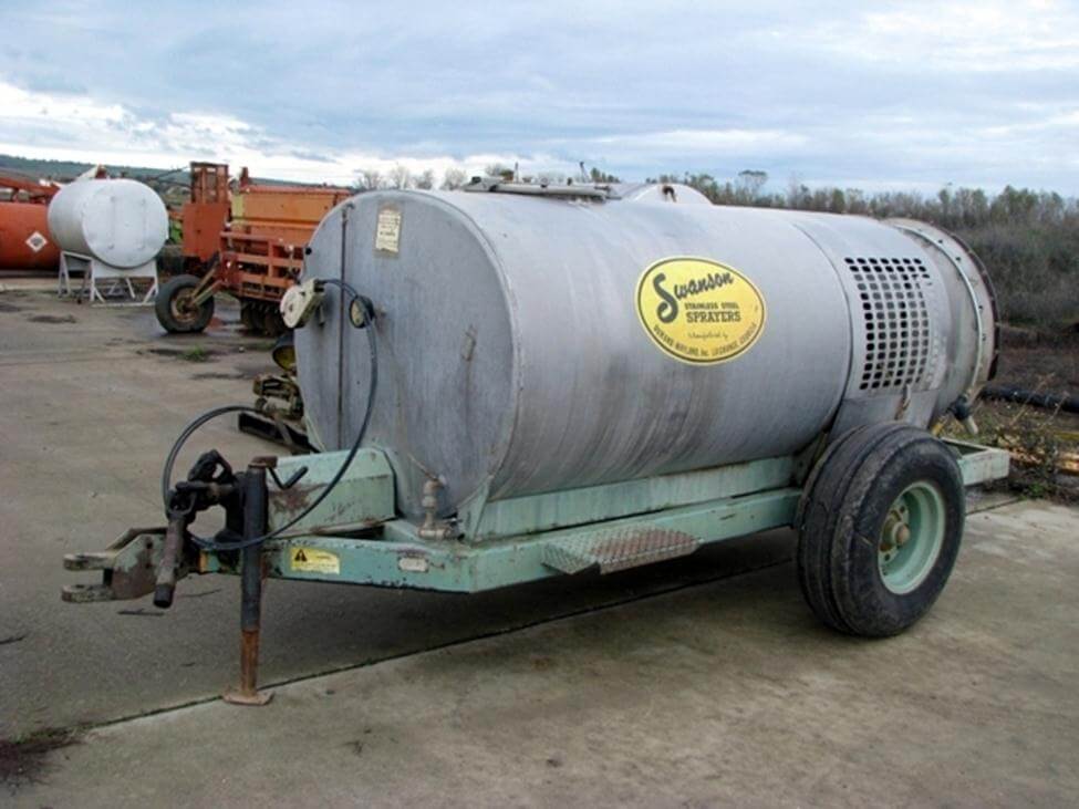
In the 1950s, Georgian Bay was home to Swanson Sprayers (now part of DW), who manufactured airblast sprayers featuring the Myers centrifugal pump. The sprayer was a good fit for the standard apple orchards found in the region. Huge canopies required high volume applications, and the rough and craggy bark harboured mites that drove the need for drenching sprays. To achieve this, sprayers traveled at 5 km/h (3.1 mph) on 7 m (24 foot) spacing, operating at 10 bar (150 psi) to emit as much as 3,750 L/ha (400 US gal./ac). At the time, a diaphragm pump could not manage this, even traveling at 0.8 km/h (0.5 mph).
A Swanson Sprayer (This one likely from Georgia, USA).
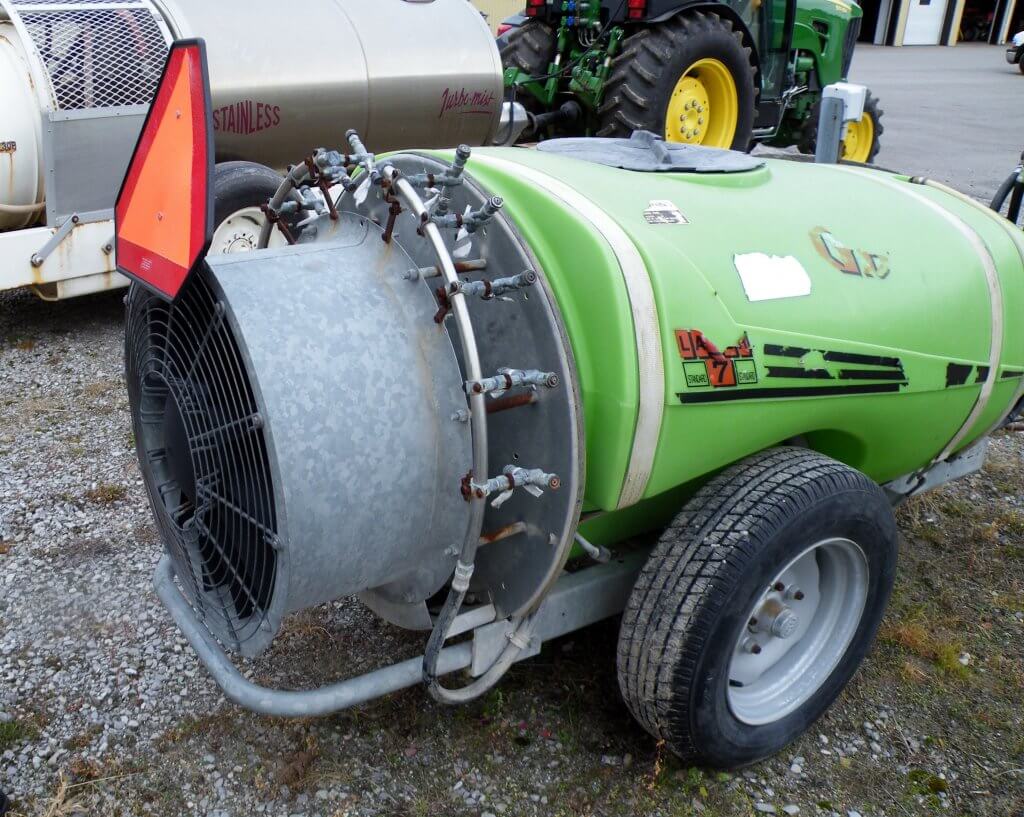
By the 1970s Holland’s Kinkelder air-shear sprayer (centrifugal pump) was introduced to Ontario and promoted as a way to use less pesticide. Perhaps ahead of their time, they never really took off because orchards were still too large for their concentrated (i.e. low-volume) applications. By the 1980s a wave of Italian-made sprayers (e.g. the Good-Boy or GB) featuring diaphragm pumps were imported into the Niagara region by distributors such as Rittenhouse.
Similar to the Kinkelder, this was one of Ontario’s last KWH air shear sprayers. RIP 2018.The Italian-made Good-Boy (or GB).
There were many cases of misuse as unfamiliar operators failed to grease direct-drive diaphragm shafts, ran the throttle beyond 540 rpm or diverted flow intended for agitation to increase flow to the booms. Decreased agitation in relatively large tanks left concentrated spray mix to clog suction filters and destroy the diaphragm pumps. It was an inauspicious start, but the diaphragm pump rallied and today we estimate that 90% of Ontario’s airblast sprayers have diaphragm pumps, while the rest are mostly centrifugal. One Ontario airblast dealer claims to sell 50 diaphragms for every centrifugal, but not in Georgian Bay.
Is it regional history or a long memory of diaphragm “growing pains” that propagate the demand for centrifugal pumps? Perhaps considerations of maintenance, expense or ease of use play a role. Dealers claim that the centrifugal pump is cheaper, but these savings are offset by custom installation costs. Perhaps weather conditions or the crop morphology make centrifugal a better fit? Let’s consider the relative benefits and limitations of diaphragm and centrifugal pumps.
Design
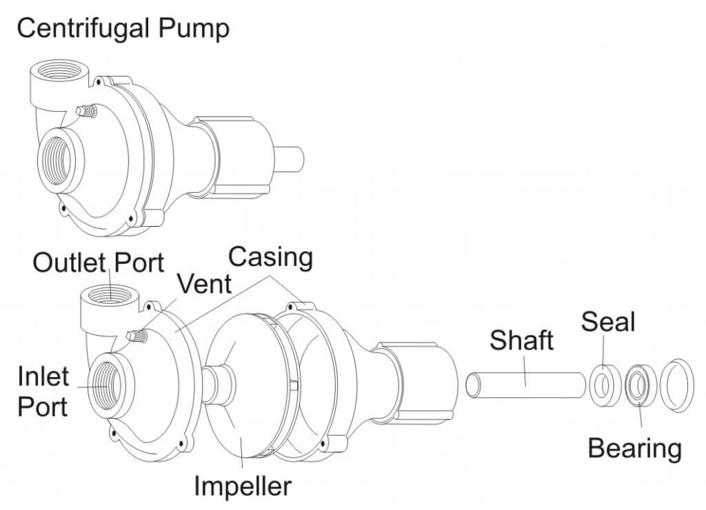
Centrifugal Pumps
Centrifugal Pump – Exploded View.
Most centrifugal pumps prime by gravity feed which is why they are located at the bottom of the sprayer. While less common in Ontario, there are self-priming versions that reserve fluid in the case, or employ clever plumbing, permitting a more accessible location on the sprayer.
Engine-driven centrifugal sprayers are artefacts in Ontario. The more common PTO-driven impeller operates at high speeds, requiring a >1:4 speed step-up mechanism (e.g. gearbox, pulley or hydraulic motor), and unlike diaphragms, they create smooth flow that does not require pulse suppression. While not technically required, most have a relief valve between the pump outlet and nozzle shut off valve to handle changes in pressure.
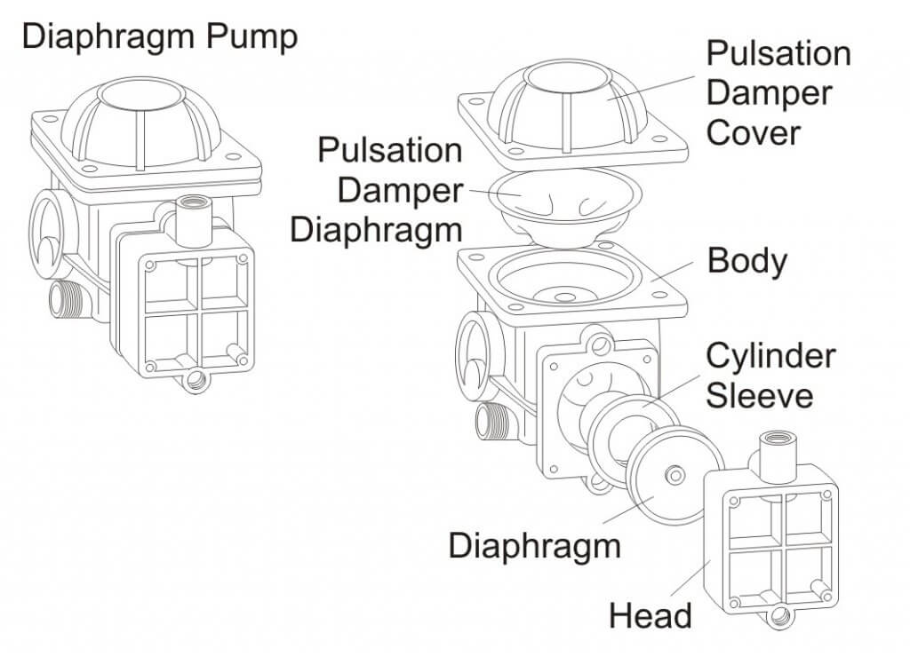
Diaphragm Pumps
Diaphragm Pump – Exploded View.
Diaphragm pumps are self-priming and readily accessible because the shaft runs through the pump to power the fan at 540 RPM, with no need to step-up. Flow is directly proportional to pump speed which in turn depends on the tractor PTO speed. A pressure regulator is used to control bypass flow, which is convenient for making adjustments in nozzle output.
Pump Flow and GUTD
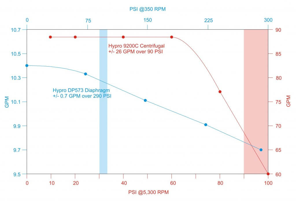
Centrifugal pumps are capable of higher flow at lower nozzle pressure and require more horsepower than diaphragm pumps. Note the large relative difference in flow for a centrifugal pump between the operating pressures of 90 and 100 psi (red curve shaded red) versus that of a diaphragm pump (blue curve shaded blue).
Relative difference in flow versus PSI at constant RPM for a common Centrifugal (red) and Diaphragm (blue) pump. Shaded pressure represents 90 to 100 psi.
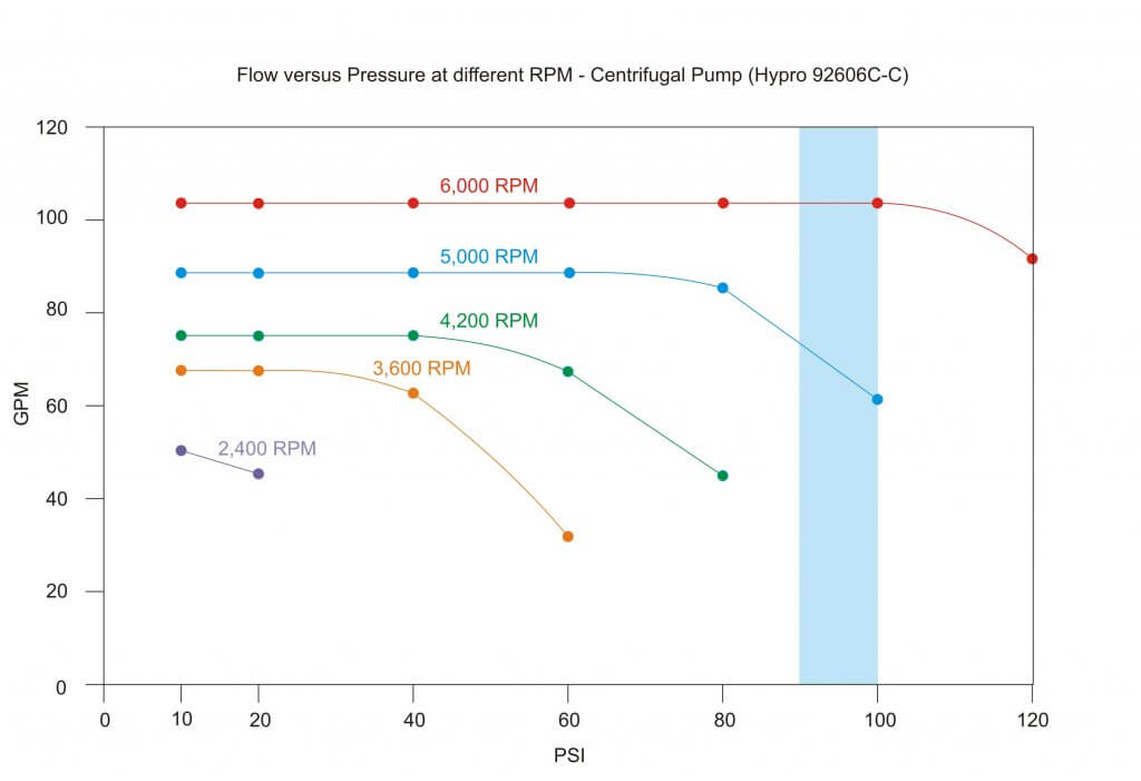
Centrifugal Pumps
The flow curve of a centrifugal pump drops off dramatically; pressure (not RPM) dictates flow. If you were to throttle back on a PTO-driven centrifugal pump, reduced flow would reduce the ability to build nozzle pressure. This means fan speed cannot be separated from nozzle pressure, and reducing air speed means re-nozzling.
Centrifugal flow at different RPM. Shaded pressure represents 90-100 psi.
While (unfortunately) still rare in Ontario, rate control monitors can be used (regardless of pump type) to calibrate output based on a target rate, speed and material flow using travel speed and flow sensors. Nevertheless, they cannot compensate for the aforementioned pressure loss at the nozzle if a centrifugal pump is throttled down to reduce air speed.
In any case, throttling back on a centrifugal pump can cause a condition called suction or recirculation cavitation (aka pinging). Tiny high-pressure air bubbles form on the suction side of the impellor, explosively pitting the impellor. The damage is similar to corrosion and it causes vibration that will wear the pump prematurely.
Any restriction on the inlet side (e.g. clogged suction strainer, collapsed/undersized line) can cause a loss of volume that can damage a centrifugal pump. “Dead-heading” (i.e. closing the outlet) is possible for a short period of time, but it quickly results in heat build-up which can cause damage.
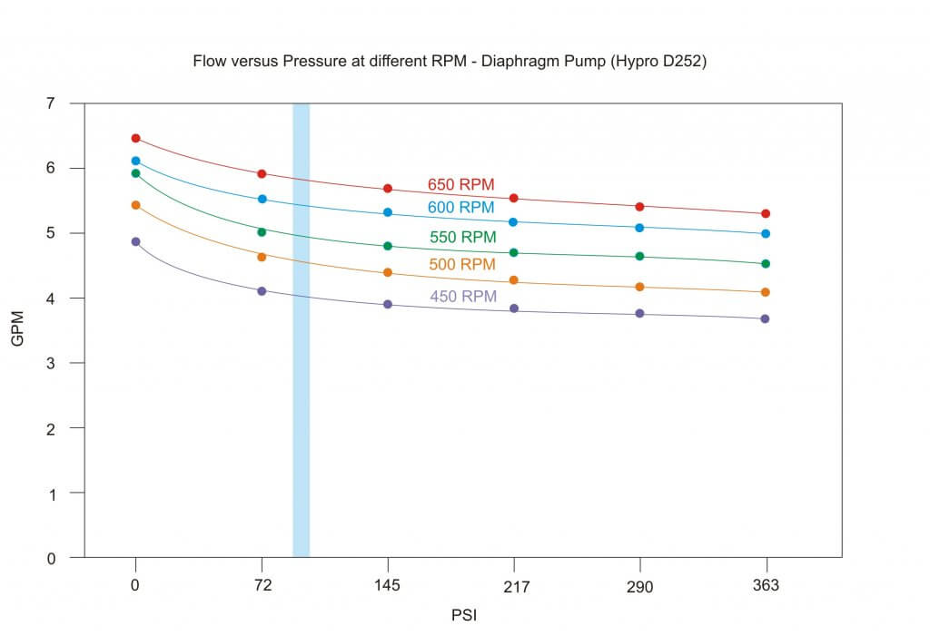
Diaphragm Pumps
The flow curve of a diaphragm pump is flatter and more efficient; RPM (not pressure) dictates flow. If you slow the airblast fan by throttling the PTO below 540 rpm, flow decreases moderately, but surplus capacity allows sufficient flow to the nozzles without pressure drop. As long as the tractor does not lug, there is less noise, lower fuel consumption and therefore operator can typically adjust the air without having to change nozzles. Even if the flow changes the pressure regulator on the diaphragm pump can be used to adjust nozzle operating pressure, precluding a change in nozzle size. Convenient.
Diaphragm flow at different RPM. Shaded pressure represents 90-100 psi.
Diaphragm pumps are capable of high pressure, but are rarely operated above 150 psi in Ontario. Molded hollow cones (eg. TeeJet’s TXR or Albuz’s ATI) operate well in the lower psi range compared to pressure-loving disc-cores. Therefore, while regulators and springs are sized according to the pump’s maximum settings, they do not reflect the usage pattern. The relatively heavy spring is too stiff to compensate for changes in pressure (e.g. driving on hills or closing one boom) behaving more like a fixed bypass and undermining a calibration. The phenomenon is discussed more detail in this article.
Maintenance
Centrifugal Pumps
A centrifugal pump with self-lubricating bearings and quality seals (e.g. carbide) that is maintained seasonally and operated in the best efficiency point of the curve will run reliably for many years.
Proponents of the centrifugal pump claim they are low maintenance (compared to the diaphragm pump). This may be anecdotal, because of the pump’s out-of-sight position on the sprayer and their tolerance for neglect. A mistreated centrifugal pump fails by degrees, often forgotten until a seal leaks or a pressure drop is noticed. In the later situation, increased flow from nozzle wear can mask the problem as the sprayer continues to cover the same number of hectares. Often overlooked, worn or misaligned sheaves/belts on a centrifugal sprayer can also cause a loss of flow. Operators might notice a tail breeze that blows spray onto the belts can cause slippage and lower the nozzle pressure.
Diaphragm Pumps
Opinion is divided on the longevity and maintenance of diaphragm pumps. Some claim they are reliable and low maintenance as long as regular oil changes occur. Others suggest the complication of connecting rods, o-rings and valves require more upkeep than the simpler centrifugal. Unlike the centrifugal pump which merely loses pressure, failure on a positive displacement pump is complete and requires immediate repair
Much depends on the diaphragm material and the products being sprayed. For example, corrosive materials (e.g. copper sulfate, urea, etc.) require polymer manifolds to minimize contact with metal. Metal manifolds do not weather well.
The diaphragm pump can run dry for extended periods. This creates heat but does not often lead to failure. Failures occur from exposure to vacuum, which can happen with dirty suction filters or long and/or improperly sized suction lines, or even lack of oil support on the compression stroke (caused by over-revving).
While three-cylinder designs may not require pulsation dampening, most require an accumulator to suppress the pulsing created by each stroke. Improper adjustment can lead to “hammering” that cracks mounts and valves, and can exacerbate rub-points on hoses. Diaphragm pumps that use direct drive shafts (i.e. carry the PTO to the fan) are subjected to the thrusting of the drive shaft during turns. It is important to keep them greased.
Summarily, the longevity and maintenance requirements for either pump design seem about equal. They depend on the products being sprayed, the quality of pump materials, and adherence to the manufacturer’s instructions on correct usage and preventative maintenance.
Conclusion
Ontario’s airblast-specific crops have become smaller, closer and denser. High liquid volumes and air speeds are typically not required. Operators are encouraged to use Crop-Adapted Spraying to adjust fan speed and nozzle output to the crop and the weather. In my opinion, the diaphragm pump facilitates this, resulting in lowered input costs, reduced drift and improved coverage uniformity. I recognize that this requires skill and effort on the part of the operator, and setting-and-forgetting a centrifugal pump can be attractive, but it’s unacceptable if it leads to unnecessary environmental impact.
In the end, the sprayer manufacturer chooses the pump, atomization and air-handling system while considering safety, effectiveness, reliability and price point. The operator must acknowledge the capabilities and limitations of the sprayer design when choosing the best fit for their operation.
I still don’t know why regions like Georgian Bay seem to prefer one pump over another. Perhaps it’s simply herd mentality. Perhaps they know something I don’t. But consider: an airblast sprayer’s average lifespan is 30 years. That’s a long time to live with a decision.
Choose wisely.
Special thanks to the many dealers, manufacturers, engineers, mechanics and end-users that helped to inform this article.
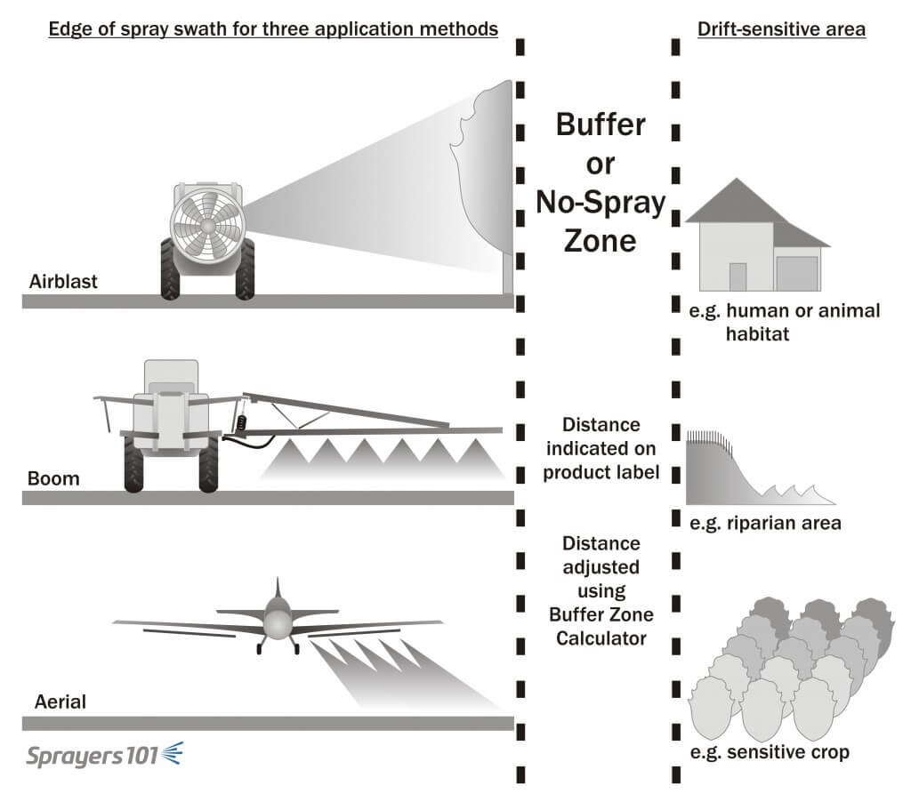
Spray buffer zones are no-spray areas required at the time of application between the area being treated and the closest downwind edge of a sensitive terrestrial or aquatic habitat. Spray buffer zones reduce the amount of spray drift that enters downwind, non-target areas.
Sensitive Terrestrial Habitats
Sensitive terrestrial habitats can include hedgerows, grasslands, shelterbelts, windbreaks, forested areas and woodlots. Crops and private properties adjacent to treated areas are not considered to be sensitive terrestrial habitats and do not require spray buffer zones. However, labelled spray buffer zones are a good indicator of potential damage to adjacent vegetation. Applicators are responsible for ensuring their spraying programs do not adversely affect neighbouring properties.
Sensitive Aquatic Habitats
Sensitive aquatic habitats can include lakes, rivers, streams (channelized or natural), creeks, reservoirs, marshes, wetlands and ponds. Temporary bodies of water resulting from flooding or drainage to low-lying areas are not considered sensitive aquatic habitats. Nor are aquatic drainage ditches or seasonal water courses that are dry at the time of application. Water body depth will determine the buffer zone distance, as indicated on the pesticide label. Downslope open water may also require a vegetative filter strip .
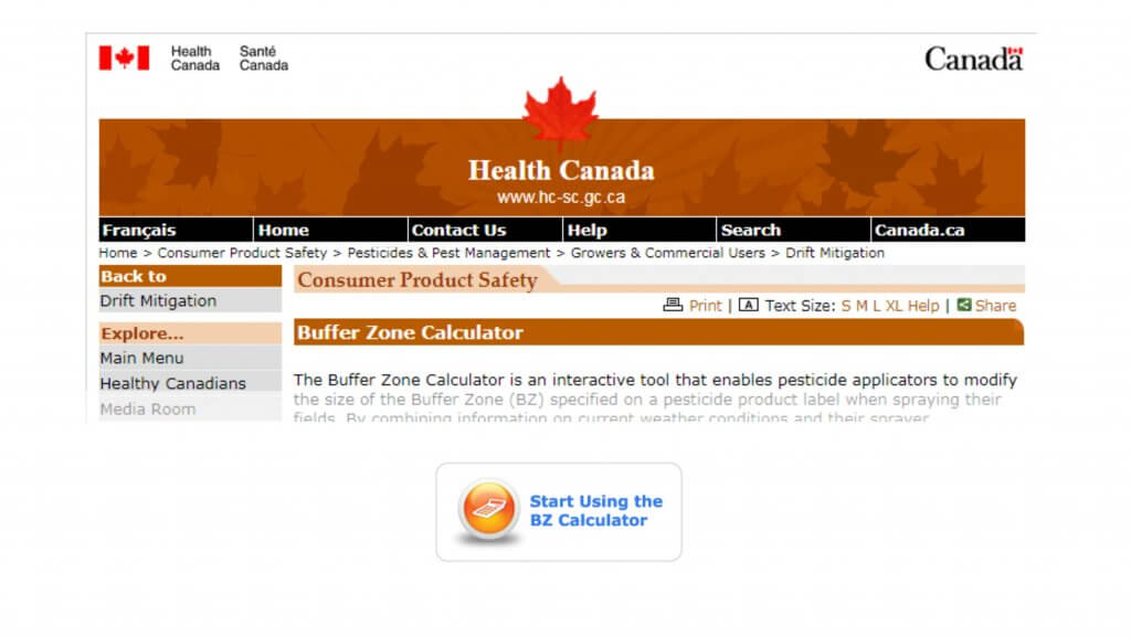
The pesticide label will indicate when a spray buffer zone is required. The distance will depend on the product used, the method of application and the crop being sprayed. In some cases, the buffer zone may be modified using Health Canada’s Spray Buffer Zone Calculator . When provincial and label restrictions differ, or label restrictions differ between tank mix partners, use the greatest distance.
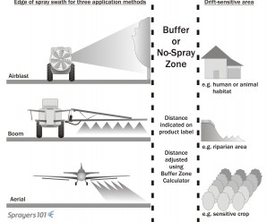
Buffer zones or No-Spray zones physically separate the end of the spray swath for the nearest downwind sensitive area.
Spray Buffer Zone Calculator
Unless forbidden by the pesticide label, Health Canada’s Spray Buffer Zone Calculator may permit applicators to reduce the size of the spray buffer zone specified on a pesticide label. To be eligible, the product label must specify a field or aerial spray quality coarser than “Very Fine” and finer than “Very Coarse”. All airblast spray qualities are applicable.
Modifications are based on meteorological conditions, sprayer configuration and the application method at the time of application. If modified spray buffer zone distances are less than provincial or municipal distances, use the greater distance.
Applicators that choose to use the calculator must retain a copy of the summary page for at least one year following the application to demonstrate compliance with label directions.
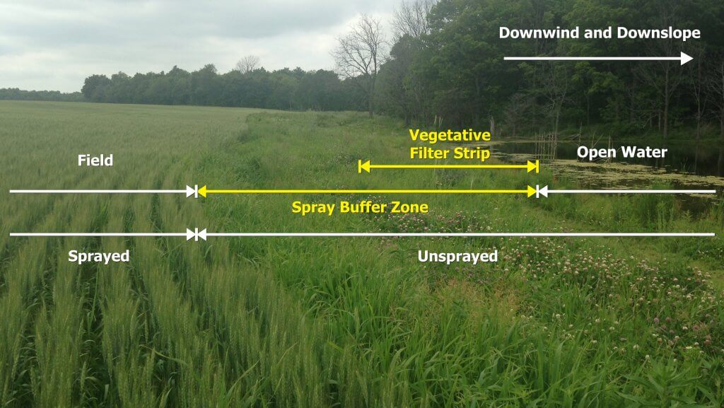
Vegetative Filter Strips
A vegetative filter strip is a permanently vegetated strip of land that sits between an agricultural field and downslope surface waters. Vegetative filter strips reduce the amount of pesticide entering surface waters from runoff by slowing runoff water and filtering out pesticides carried with the runoff.
Pesticide labels may require a vegetative filter strip, or recommend one, as a best management practice. They must be at least 10 metres wide from edge of field to the surface water body and be composed primarily, but not exclusively, of grasses.
Spray buffer zones do not apply to vegetative filter strips unless there is a pre-existing sensitive terrestrial habitat within them. Therefore, vegetative filter strips may overlap spray buffer zones when open water is both downslope and downwind (see illustration). In this case, the minimum 10 metres vegetative filter strip distance must be observed, but the set-back can be larger based on spray buffer zone, provincial or municipal restrictions.
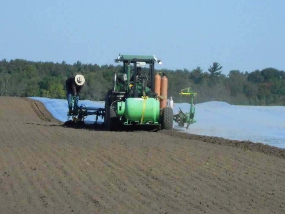
Soil Fumigant Buffer Zones
Soil Fumigant Buffer Zones are mandatory, untreated perimeters surrounding the treated field. They limit user exposure and increase the protection of workers, bystanders and the environment. The distance will depend on the application method, product rate and field size, as indicated on the pesticide label. An Emergency Response Plan is required when residences or businesses are located within 90 metres of the buffer zone perimeter.
Soil fumigant buffer zones have a time component. This Buffer Zone Period begins at the start of the application and ends a minimum 48 hours following the application. Respiratory protection and stop-work triggers, as specified on the pesticide label, will apply to anyone present in the buffer zone area during the buffer zone period.
Buildings and residential areas within the soil fumigant buffer zone must be unoccupied during this period. Unless in transit, non-handlers (including field workers) must be excluded from the soil fumigant buffer zone during this period. Entry is permitted for fumigant handlers with appropriate certification, emergency personnel and local, provincial, or federal officials performing inspection, sampling, or other similar duties.
Soil fumigant buffer zone signage must be posted within 24 hours prior to the application and remain posted until the buffer zone period expires. Signage must include, but is not limited to, the date and time the buffer zone period ends and the name, address, and telephone number of the applicator. Soil fumigant buffer zone signage must be located at the outer perimeter of the buffer zone, at all entrances to the field, and along likely routes where people not under the owner’s control may approach. Soil fumigant buffer zone signs are in addition to, and do not replace, fumigant application block signage .
Applicators must develop a written Fumigation Management Plan prior to the start of any application. The plan outlines key steps to ensure a safe and effective fumigation, including site conditions, buffer zones and emergency response planning. Both the owner/operator of the fumigated area and the fumigant applicator must retain signed fumigant management plans as well as a summary of Post-Application Procedures for two years following the application.