Editor’s Note: Any brand-specific references or recommendations in this article are based on the author’s experience. Sprayers101 endeavours to preserve brand independence and impartiality to best serve our readers. This article was originally posted in 2018.
During my many years of work in the Australian vegetable and horticultural industry, I am continually asked:
Q. What is the best spray unit to use?
My answer is simple:
A. The one that has been correctly set up and matched to the crop you are spraying.
That can be hard to achieve, especially in vegetable crops where the target can vary enormously from bare ground to upright leaf crops (e.g. onions), to horizontal leaf crops (e.g. potatoes and brassica).
Generally, I have found that air-assist booms offer the best starting point for achieving good spray coverage of vegetable crops. However, like any spray boom, they must be set up correctly. Air-assist booms are more expensive and require a few more horses to operate, which is why most Australian vegetable growers prefer to make do with a non air-assist boom.
So, if air-assist isn’t an option, it then becomes imperative to determine the most suitable nozzles for their particular requirements. I have worked in many vegetable crops over the years. I’ve held my share of “fluorescent dye nights” and checked spray coverage and canopy penetration with many grower groups. Based on my experience, there are three types of nozzles I recommend for most vegetable crops:
Nozzle #1: Air Induction Flat Fan
Here’s what I say when the grower (inevitably) asks which nozzle is the best for every task:
Using only one nozzle will compromise some aspect of a series of applications. However, the Syngenta 110 025 air induction nozzle generally performs well. Manufactured by Hypro it creates more droplets per liter than other air induction nozzles of the same size (as of 2018). (Editor’s note: as of 2025, a likely North American equivalent is alternating-direction Syngenta 3D 90’s. They produce a high-velocity Extremely Coarse-Ultra Coarse spray quality and the manufacturer claims they improve the penetration of broad leaf canopies over conventionally-angled sprays. However, when drift potential is low, travel speed is reasonable, and boom height is low, alternating-direction Defy 3Ds produce a Medium-Coarse Spray quality which may be more conducive to retention on hard-to-wet vertical targets).
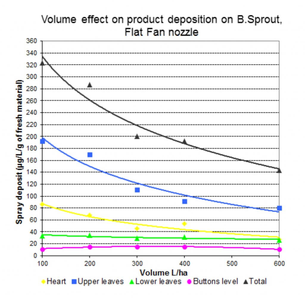
As long as the crop isn’t too large (e.g. later season), I recommend this nozzle with lower water volumes. This is because I tend to see more application issues arising from excessive water rates that wash product off the plant. Unless you are after soil borne diseases, avoid run-off and wastage by using the SAI 110 -25 with volumes of about 200 L/ha. The following graph shows the results of application volume on brussels sprout coverage (per Syngenta UK).
Nozzle #2: Narrow Spray-Angle Flat Fan
When I am trying to increase canopy penetration, I like the Syngenta Vegetable Nozzle (SV65-04 flat fan). I feel the narrow spray fan angle delivers a directed spray pattern into the crop canopy which can significantly improve penetration. This is a good fit for late-season insecticide and fungicide sprays in brassica crops, where pests and diseases can be hidden deep in the crop canopy.
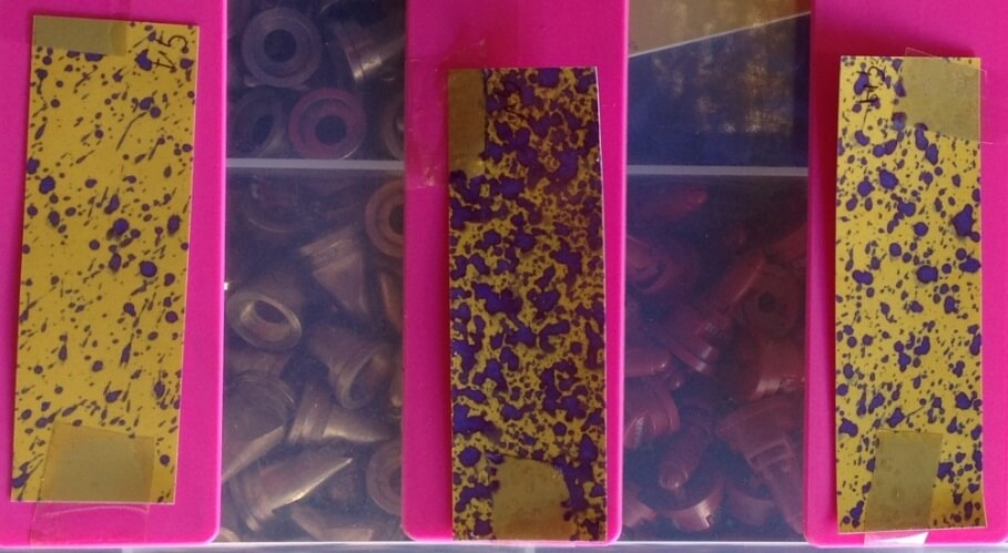
I worked with a vegetable grower who was having trouble controlling sclerotinia in his mature fennel crop. The target was the base of the stem, deep in the canopy. In the following image you can see the water sensitive paper taken from ground-level in the canopy. The nozzles used from left to right are; Hardi Twin AI 110-05, Syngenta 65-06 vegetable nozzle and Syngenta AI 110-05. Coverage was estimated using the SnapCard app (freely available for iPhone and Android platforms). (Editor’s note: as of 2025, Syngenta’s silver 06 and gold 08 vegetable nozzles are not available in North America. They produce high volume, slow-moving, Coarse-Very Coarse sprays. TeeJet’s Visiflo is a 65 degree tip, but produces too fine a spray quality to be serviceable. As spot-spraying is increasingly adopted, the development of narrow-angled nozzles is anticipated and may offer a reasonable alternative.).
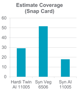
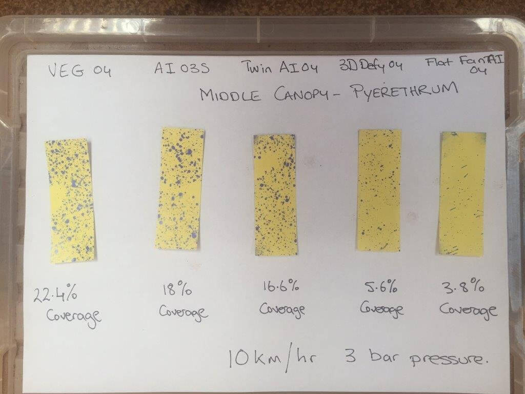
So, I know pyrethrum is a flower and not a vegetable crop (think chrysanthemum), but it can be hard to penetrate, so this is a good example. We compared five nozzles and estimated coverage using SnapCard. The Veg 65-04, AI 110-035, and Twin AI 110-04 seemed to improve coverage over the Defy 3D 85-04 and conventional AI 110-04.
For broadacre farmers (i.e. field or cereal crops) the SV65 flat fan nozzle has also proven to be extremely successful at penetrating thick standing stubble residue when using pre-emergent herbicides. Likewise, it performs well when targeting lower leaves during fungicide applications. Again, I believe that this is due to the narrow fan angle of the spray giving a more direct spray down through both the stubble and the current season’s foliage. Be attentive to nozzle spacing and boom height when using narrow fan angles to ensure correct overlap and complete coverage.
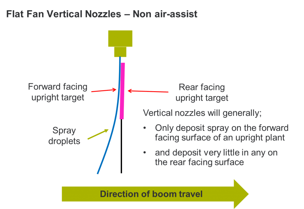
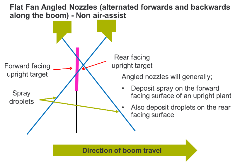
Nozzle #3: Angled Flat Fan
For onions and broadleaf crops (e.g. potatoes and beans), I feel the nozzles that have their spray fans angled forwards and backwards along the (non air-assist) boom are best suited.
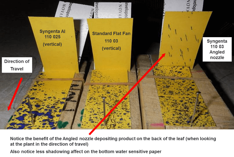
The following image shows coverage from angled sprays on simulated upright targets in the field using water sensitive paper.
The Syngenta angled nozzles are designed with a 30° incline intended to improve foliar coverage down to the lower leaves on some vegetable crops. Although originally designed for use in potato crops, I have also had success in other vegetable crops such as onions and leeks. (Editor’s note: as of 2025, the Gold 04 and Orange 05 potato nozzles do not appear to be commercially available, although possibly in Ireland. They produced a ~Medium spray quality at an angle similar to that of the vegetable nozzles).
Summary
No matter the nozzle choice, or how good the application technique may be, the priority should be to manage disease and insect pests early in crop development. If you are trying to control heavy pressure from disease or insects and it’s deep within the crop canopy, often, you’re going to come off second best. Prevention is always better than cure, no matter what crop protection product you are spraying.
With that caveat, I’ll leave you with my suggested nozzle choices. Preferably, I would suggest installing (at least) a triplet nozzle selector to quickly change between three nozzles for each crop.
Crop
Growth Stage
Water Volume (L/ha)
Suggested Nozzle
Notes
Cabbage
Small, open
100-200
Air Induction
Run-off is the enemy of small plants.
Hearted
300-800
65 ° Fan Angle Nozzle
Angled spray important to get spray under top leaves. Use twin cap option for volumes greater than 300 L/ha.
Carrots
Small
100-200
Air Induction
Carrots are good at catching spray. Angling nozzles e.g. Twin Cap will give best results.
Large
200-400
65 ° Fan Angle Nozzle
65º fan the best for penetrating to crown. Apply volume of 200 L/ha, increasing to 400 L/ha in denser crops. Avoid air induction (aka bubble jet) and hollow cone nozzles for later application timings.
Brussels Sprouts
Small, open
100-200
Syngenta AI 110025
Run-off is the enemy of small plants.
Large
200-300
Syngenta 3D nozzle 85 04 or 85 05
Leeks
Small
100
Syngenta 3D Nozzle 85 03, 85 035 and 85 04 cover both sides of the plant.
Coverage, run-off and missing the target are the problems likely in Leeks. Angled spray forward and backwards is important. High Volumes = Run-off.
Large
200-300
Syngenta 3D nozzle 85 04 or 85 05
Angled spray forward and backward. High Volumes = Run-off.
Lettuce
Small, open
100-200
Air Induction
Run-off is the enemy of small plants.
Hearted
300-800
65 ° Fan Angle Nozzle
Onions
Small
100
Syngenta 3D Nozzle 85 03, 85 035 and 85 04 cover both sides of the plant.
Coverage, run-off and missing the target are the problems likely in onions. Angled spray forward and backwards is important. High volumes = run-off.
Large
200
Syngenta 3D Nozzle 85 04 or 85 05
Angled spray forward and backward to cover both sides of the plant.
Potatoes
Prior to row closure
100
Syngenta Pre-em 03 nozzle
Angled spray forward and backward.
After row closure
Syngenta 3D Nozzle 85 03, 85 035 and 85 04
Pre harvest (desiccation)
200-400
Syngenta 3D Nozzle 85 04 or 85 05
The desiccation of very large canopies may require up to 400 L/ha of water on the 1st application.
Peas and Edible Beans
Small
100
Syngenta 3D Nozzle 85 04 for 7–9 km/hr. Syngenta 3D Nozzle 85 05 for 10–12 km/hr.
Medium spray quality and use higher water volumes in dense crops. All nozzles 0.4-0.5 m above top of crop.
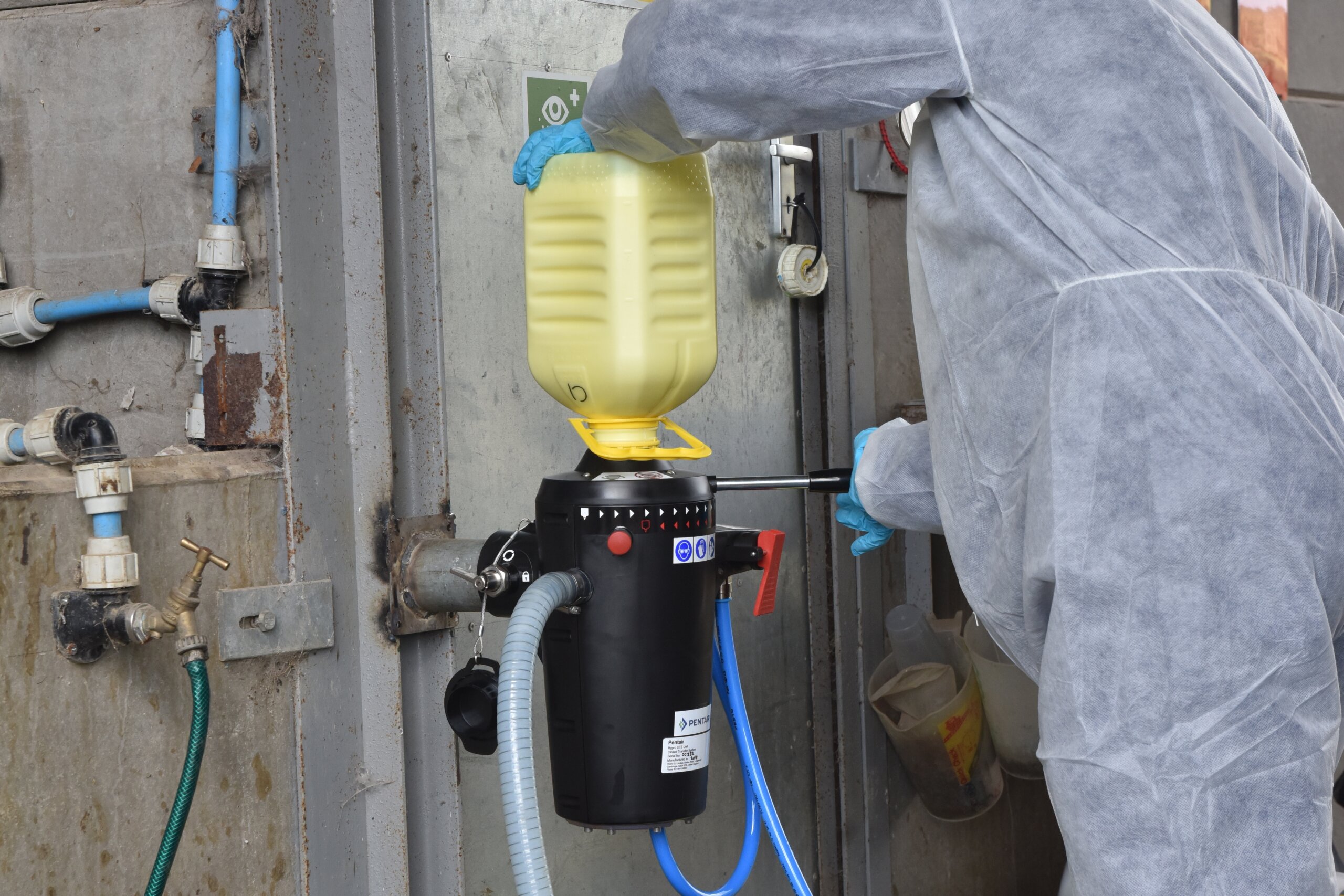
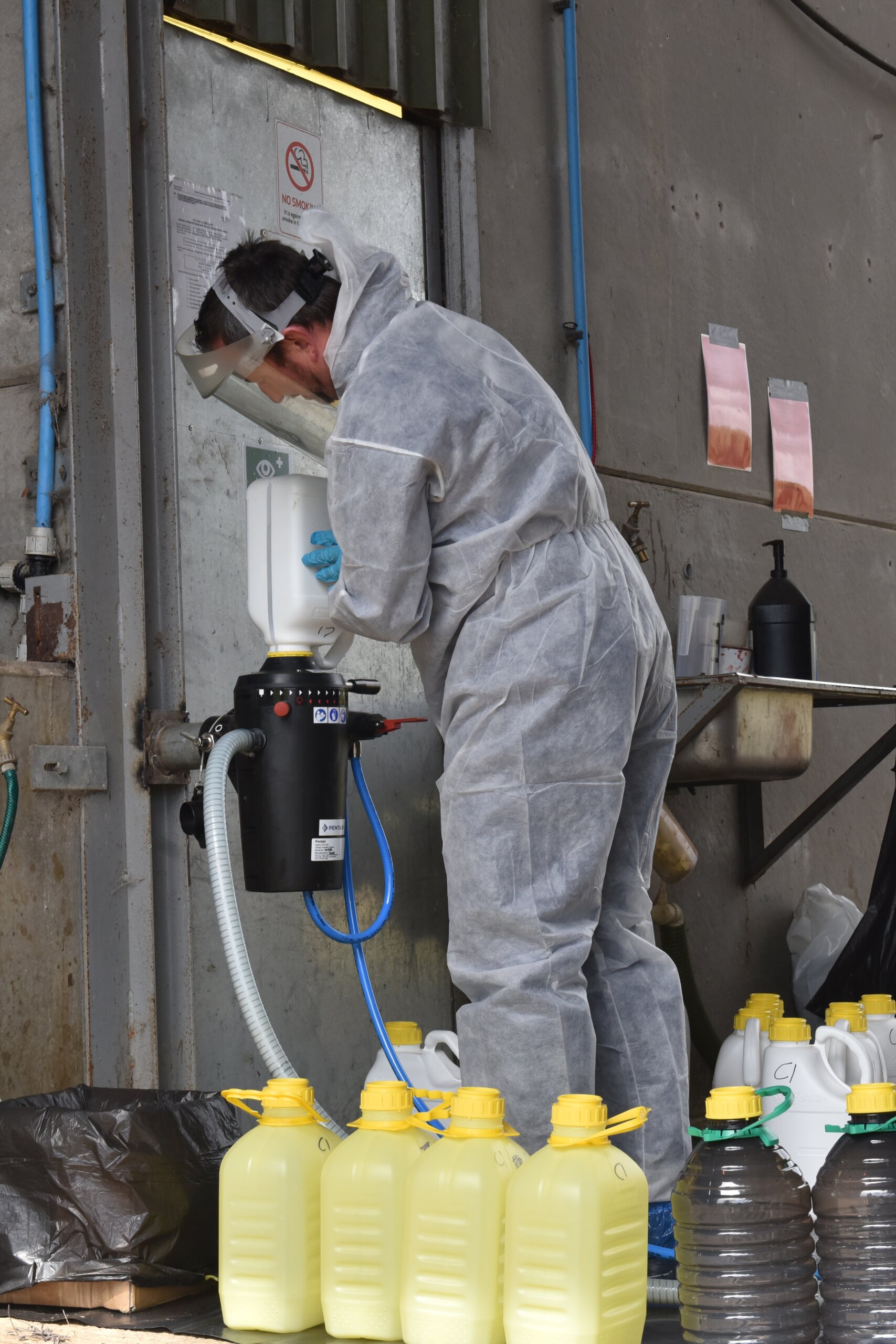
Closed Transfer Systems (CTS) permit the direct transfer of pesticides from container to sprayer while isolating the process from the operator and the environment. Similar systems are already used with bulk pesticide containers and in other industries to dispense a wide range of liquids from household products to industrial chemicals. In the case of small-volume containers (e.g., up to 20 L), these systems include an integrated container rinsing function.
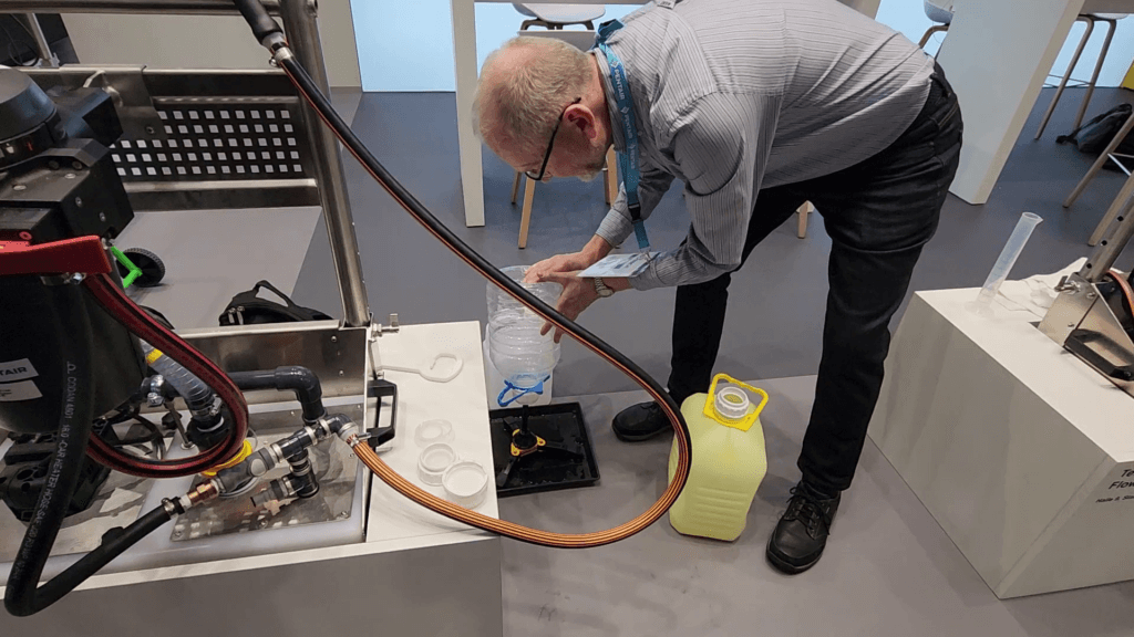
The UK’s Iain Robertson testing Pentair’s Cleanload Nexus Coupler
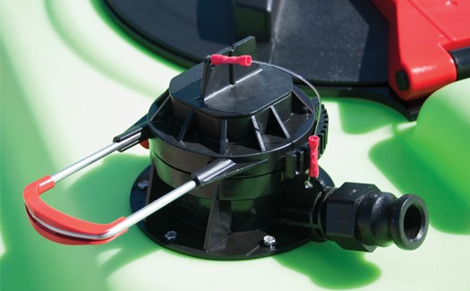
CTS are comprised of two parts: The Cap (or Adaptor) and the Coupler. The CTS cap is either pre-fitted on the pesticide container, or the user must remove and replace the existing, non-CTS cap with an adaptor. Generically, the container is then locked into the coupler, and a valve in the cap or adaptor opens to permit chemical to be drawn out. If a partial amount is required, the valve can be closed to re-seal the container for safe removal, and the coupler and lines can then be rinsed. If the full amount is required, then the container is also rinsed prior to removal.
Regulatory Requirements: Canada
Canada’s Pest Management Regulatory Agency (PMRA) considers the requirement for closed transfer when products go through their natural re-evaluation cycle. They define it as follows:
“A closed system means removing a pesticide from its original container, rinsing, mixing, diluting, and transferring the pesticide through connecting hoses and couplings that prevent exposure to the pesticide.”
The requirement is primarily a means of reducing operator exposure and point-source contamination during filling, but can also be used to impose rate restrictions, or in response to reformulation. In recent years, several pesticides have had statements added to the labels regarding the requirement for a closed transfer system. They have stated that there have been three scenarios that they have included closed systems on labels:
The registrant requested closed systems be used in the occupational risk assessment.
Closed systems were required when triggered by the occupational risk assessment as a form of mitigation to reduce exposure to the mixer/loader. This is the most common reason it gets added.
Closed systems were used in the specific exposure study submitted to PMRA that was used in the risk assessment.
As standardized language is developed, Canadian operators can expect to see statements that vary in their specificity, such as in the following two examples:
Product 1: “Requirement for additional personal protection equipment (PPE) and engineering controls when mixing/loading and applying to various crops.” Product 2: “Closed mixing/loading systems are required. A closed system means removing a pesticide from its original container, rinsing, mixing, diluting, and transferring the pesticide through connecting hoses, pipes, and couplings that are sufficiently tight to prevent exposure of any person to the pesticide or rinsing solution.”
Questions and concerns have been raised by registrants and growers as these changes have appeared on pesticides with particularly important actives. As of 2025:
Products with standard CTS label statement:
Lorox L Herbicide
Ethrel PGR
Dibrom Insecticide
Products that require CTS without standard label statement:
Bravo ZN Fungicide (bulk totes only, chlorothalonil in 10 L jugs does not require CTS)
Captan 480 SC and Captan L Fungicide (only if open cab AND exceeding a maximum L/day threshold)
Products that may require CTS but not clear on the label:
Sevin XLR Insecticide – “use a closed mixing system”
In some cases, registrants have avoided the requirement by splitting the label rate and promoting multiple applications to ensure rates do not reach the PMRA’s threshold for closed transfer. Another strategy is to remove small-volume formats and rely on Intermediate Bulk Containers (IBC or totes), which already employ closed transfer. If neither option is available, registrants may face expensive changes (which are currently unspecified) to their injection molding process. This is assuming North American small-volume container packers respond to emerging Canadian requirements.
Commercial horticultural and specialty crop growers (or field croppers with smaller acreages and diversified crops) are more likely to purchase pesticides in small-volume containers as opposed to a tote. For growers, the practical requirements for compliant closed transfer are not well understood. Most do not currently have CTS and feel a retrofit is overly burdensome (e.g. slow, expensive, complicated), incompatible with their equipment, or redundant with conventional PPE.
As Canadian agriculture comes to terms with these regulatory changes, the European experience offers valuable insight.
Regulatory Requirements: Europe
In Europe, reducing operator exposure and point source contamination during filling has long been a regulatory priority. Regulatory requirements for CTS are slated or already exist. The following dates are “fluid estimates” that will depend on the politics of each country. At the time of writing, the Netherlands are planning to make it compulsory on liquid formulations by 2025. Denmark will follow by 2024-25 and Belgium by 2026. The Czech Republic already stipulates about 12 separate products must be used in combination with CTS, and a blanket requirement is under discussion. In some cases, growers will be granted a three-year transition period before they must show that they have a capable CTS. Currently the UK doesn’t yet have any concrete targets, but they have been testing CTS since 2017 and their experiences have informed product development and the creation of international standards. According to a 2023 article in EI Operator, CropLife Europe stated that Europe is on track to make CTS available to all European farmers by 2030
Recycling
According to easyconnect (c. 2024), Germany is on the cusp of agreeing to accept both jugs and caps for shredding. Currently the caps are collected separately (if at all) because they aren’t typically rinsed. This is the same as in Canada.
Cap and foil collection awaiting disposal.
However, because the transfer systems also rinse the connection, the caps are down to the same 0.01% residue limit as the jugs, so as long as they’re dry, they’re both recyclable. Discussions are ongoing with France to make the same agreement.
ISO definitions of CTS
The 2021 publication of ISO 21191 has greatly facilitated CTS development. The standard defines what a CTS is and specifies the testing methods and compliance criteria for both operator and environment-related safety. Summarizing key points in the ISO:
The CTS shall
connect to containers and application equipment;
control flow and measuring of all or a part of the container content;
rinse the container into the application equipment;
flush the CTS equipment as well as the interface;
permit operation while using appropriate personal protection equipment specified on pesticide label and any associated operator’s manual;
have clearly labelled controls;
be designed to avoid any return of liquid to the clean water supply.
The CTS shall not
cause leakage when the device is connected to the mix tank or application equipment;
influence the circulation system of the connected application equipment;
allow the introduction of air that promotes foaming or reduces pump performance;
leave a residue level of more than 0.01% of the containers nominal volume following rinsing.
The ISO was reinforced by a 2023 Crop-Life Europe study that tested three systems applying for ISO certification. It demonstrated a more than 98% reduction in operator exposure (while using gloves) for the easyFlow M, GoatThroat, and Cleanload Nexus systems. These systems, and others, are described below.
Note: when using crop protection products, it remains a legal obligation for operators to wear the personal protection equipment indicated on the product label.
Commercial Systems
Pesticide container compatibility is fundamental to the success of any CTS design. There are exceptions, but many agrichemical companies in Europe and North America already employ a 63 mm screw cap for small-volume containers. According to the EPA (EPA 40 CFR Part 165 Subpart B), liquid agricultural pesticides in containers that are rigid and have capacities equal to or larger than 3 liters must have a screw cap either 63 or 38 mm in diameter and at least one thread revolution at 6 threads per inch. Depending on the CTS design, jugs may or may not require a tamper-proof foil. As of 2024, the first available jugs in the U.K. did not have foils.
The following systems are compatible with the 63 mm cap and are emerging as viable options at the time of writing. Some have been commercially available for several years and others are either new or still in development. Cost and availability will vary based on regional distribution and demand. Interested readers are advised to contact the manufacturer to confirm compatibility with their preferred products.
The easyFlow was developed with support from Bayer and has been available for more than 10 years. It requires the operator to remove the existing container cap and replace it with the easyFlow adaptor, which features a built-in knife that automatically cuts any foil seal. It is compatible with container sizes between 1 and 15 L. There are three versions of the easyFlow coupler.
easyFlow
The original easyFlow coupler installs directly to the sprayer tank. Once the pesticide container is joined (maximum 10 L format), product pours via gravity straight into the sprayer tank. The container can then be rinsed using an external water source (e.g. via a garden hose) with a min. ¾” diameter, anti backflow valve and water pressure between 3-6 bar.
easyFlow directly mounted on sprayer tank (image from FreeForm)
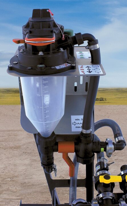
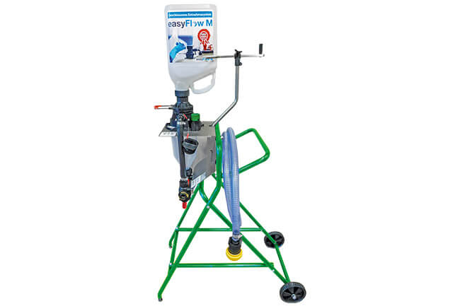
easyFlow M
The easyFlow M is a standalone coupler that supports containers over 10 L and permits dosing via an integrated measuring unit just below the mounting point. The measuring unit holds up to 2,250 ml with a minimum volume of 60 ml and graduations of 20 ml (50 ml over the 400 ml mark). Product transfer is achieved either by gravity, or by a pump (e.g. Teed to the suction side of the sprayer pump).
easyFlow M mounted on separate transfer station (image from FreeForm)
According to agrotop, a 5L container under suction took 2-2.5 minutes to empty and clean during the Croplife study. For reference, some operators claim they are able to drain and triple rinse in less than a minute using a traditional pour into an inductor. An operator in wheat aims to fill in 5-10 min depending and uses 5-10 jugs. On the other hand, CTS users have claimed a “hidden savings” from the overlap in operations where the product from one jug is still entering the system as another is being drained and a third is being prepared. AgroTop sells an optional vent spike called a “Chucker” that makes the process faster still, but penetrating the jug raises questions about ISO compliance.
Empty containers can then be rinsed before removal, or partial containers removed leaving the adaptor on the jug. While this unit can be mounted on the side of the sprayer, most UK farmers that have trialed this system opted to install it on a portable cart.
This system is still under development and information is limited. The easyFlow QF coupler reputedly has all the features of the M but is compatible with all manner of container and employs a 12 VDC supply to automatically meter the dose (starting from a minimum 1 L volume). The rinsing process is electronically automated as well.
Videos of the easyFlow systems in use can be seen hereand here. In the United states, these couplers are carried by Greenleaf Technologies. In Canada, it is also carried by FreeForm, a plastic molding company out of Saskatchewan.
US-based GoatThroat has provided industrial liquid transfer solutions since 2001. Their CCS-8600 series requires the operator to remove the existing container cap and replace it with an adaptor with a siphon tube (which also pierces any foil). The container is then pressurized by a hand pump or compressor, forcing chemical into a measuring cylinder before it’s drawn into the sprayer. A clean water line then rinses the container (if emptied completely) and system before decoupling. The adapter can be left on containers if using partial volumes.
Comparatively, this system transfers and rinses more slowly than other small-format container systems and is entirely manual with multiple steps to transfer product. However, it now has a compressor option to replace manual pumping and it is highly customizable, making compatible with any container from a 1 L jug to a 1,000 L IBC tote. Further, its ability to transfer as little as 5 ml increments makes it a good option for small-acreage horticultural, specialty crop, and research farms where accurate partial loads are prioritized.
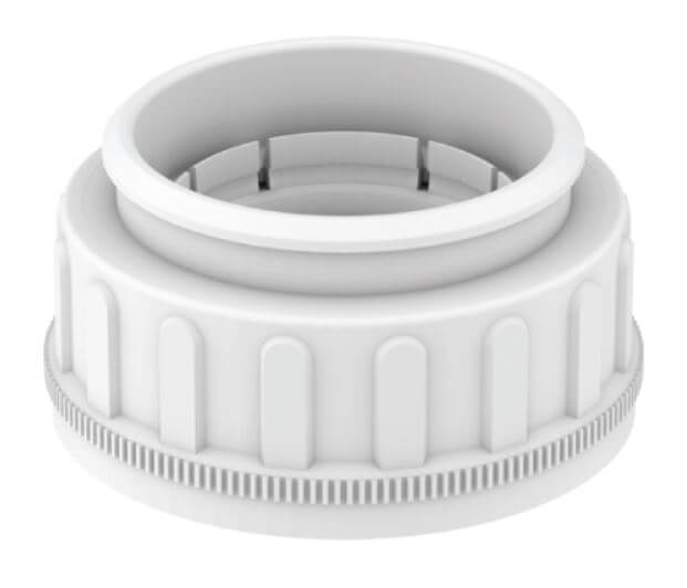
The easyconnect cap was originally developed by IPN Scholle with the support of BASF and is currently under development by Easy Cap and United Cap. It is compatible with container sizes between 1 and 15 L (possibly 20 L).
Because the cap is factory-fitted, it never has to be manually unscrewed or removed and works without requiring a tamper-proof foil. Its success is contingent on major agrochemical manufacturers agreeing to pre-fit it on their products. This has been facilitated by the easyconnect Working Group (ECWG), a consortium of ten major agrichemical companies, including those selling biological products and liquid fertilizers, that are supporting the European implementation of this format.
BASF displayed their compatible coupler, the ezi-connect at the 2023 Agritechnica in Hanover, Germany. Transfer requires the operator to snap off a dust cover, invert the container, and connect and lock it into the coupler. Another lever advances a probe and allows partial volumes to be dispensed via a vacuum generated by the hopper. Finally, a trigger controls rinsing water and undoing a catch allows the assembly to be rotated to improve cleaning without removing it.
Easyconnect will be factory installed on 1, 5 and 10 L containers in 2024. This will not be the entire portfolio from all agrichemical companies in the easy connect working group, but will represent a “significant amount” that will demonstrate commitment. In 2022, Syngenta released some information about their new jug format, the Evopac. In November 2024, Syngenta released this short video describing the design, which has the easyconnect cap and several features informed by sprayer operators to make it as safe and convenient as possible. The ezi-connect coupler will be launched in Europe in the 2025-2026 season.
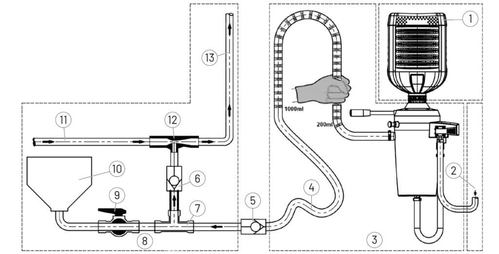
The Cleanload Nexus is a JKI-approved coupler designed for use with easyconnect caps on 1 to 15 L containers. The supplied 25 mm x 4 m suction hose can be connected by teeing it directly into the sprayer suction line ahead of the venturi (mounted to sprayer) or using a suitable dry-break coupler (mounted on a portable transfer station). The supplied 16 mm x 2.5 m rinse water hose connects to a clean rinse water source either on or off the sprayer.
The Cleanload Nexus in use
It is entirely mechanical and has just two manual controls. The first is a lever that locks the cap in place. Rotating the lever controls the emptying rate, which is between 0.5 and 1 L/sec at 4 bar, depending on liquid viscosity. The time to empty and rinse a 15 L container at 3.5 bar is about 2 minutes, and users have stated that this is as fast or faster than traditional pouring and rinsing methods.
For dosing, it currently relies on the operator using scale markings on the side of the pesticide container. It has been noted that the plunger mechanism displaces sufficient volume that it must be accounted for when reading graduations. Alternately, the calibrated suction hose connected to the sprayer can be used to assess larger volumes. The hose is, according to many, not a viable method for dosing and improvements are reputedly under development. Neither approach can achieve the ISO +/- 2.5% dosing accuracy, so Pentair has developed a dosing cylinder add-on that sits between the Cleanload Nexus and the sprayer and provides +/-1% accuracy (anticipated launch was in November 2023). A new measuring device, the Ezi-Connect VacTran Measure Unit by Wisdom Systems, was introduced in 2024 and is discussed in this article from EI OPerator.
Plumbing diagram for the Cleanload Nexus (from Pentair website).
While this video depicts 4 quarter-turns separated by 10-15 seconds rinses, practical application sees the simultaneous full rotation of the jug during a 30 second rinse. While the unit will rinse itself, some keep a dedicated jug full of clean water on hand and run that through the system last to ensure it’s left in a clean state. Note: operators say they only thoroughly rinse the cap when using a partial volume.
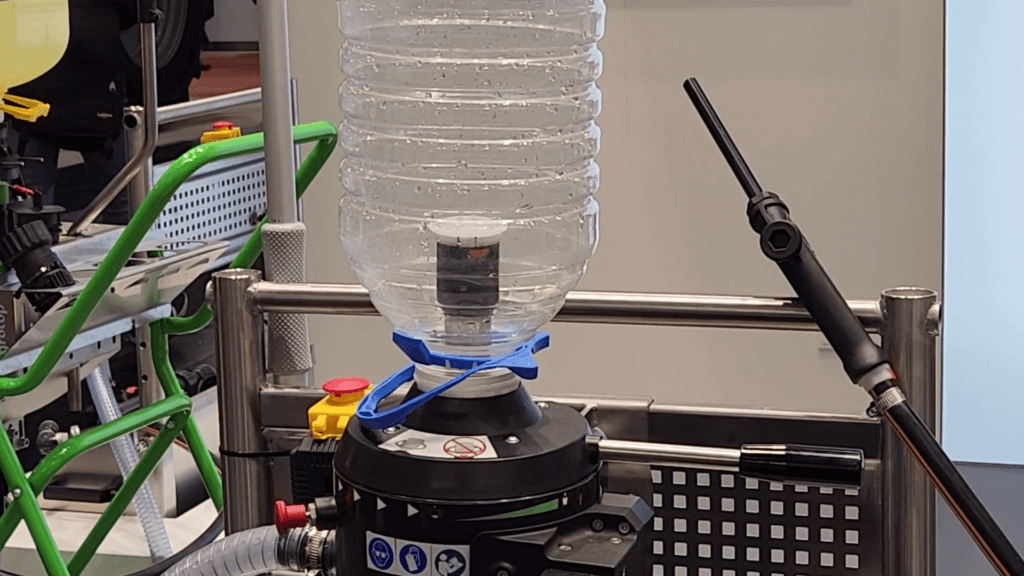
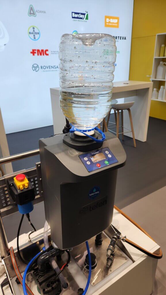
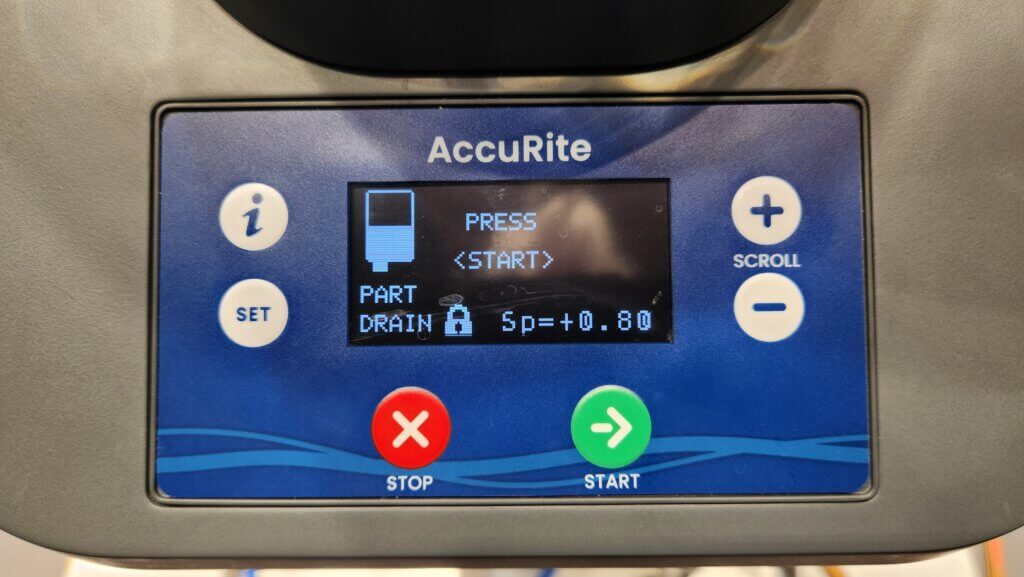
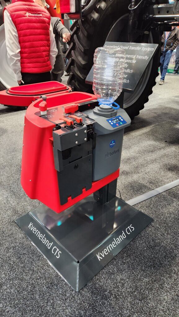
Israel’s Tefen has produced dosing pumps and flow products for many years and began field testing the AccuRite CTS coupler in 2022. With a single digital interface to operate the filling process and mobile capabilities for remote management and cloud-based record keeping (e.g., date, time and chemical usage). It is designed to work with the easyconnect cap on containers ranging from 1 to 20 L. This is slow compared with the ~60L/min. from the Pentair system, but Tefen is working to improve the speed.
Its diaphragm pump can deliver partial volumes at 0.1 L increments with an accuracy of +/- 2.5% of the smallest container used, and a minimum of 0.5 litres remaining in the container. Skip to the 1:50 mark to see the product reviewed (no English) in this video. In 2024, the following instructional video was released:
We saw one moulded into a Kverneland sprayer (now owned by Kubota) that was designed to couple with the current induction bowl. This is the first time a sprayer company has altered their design to accommodate a CTS and it points to the future.
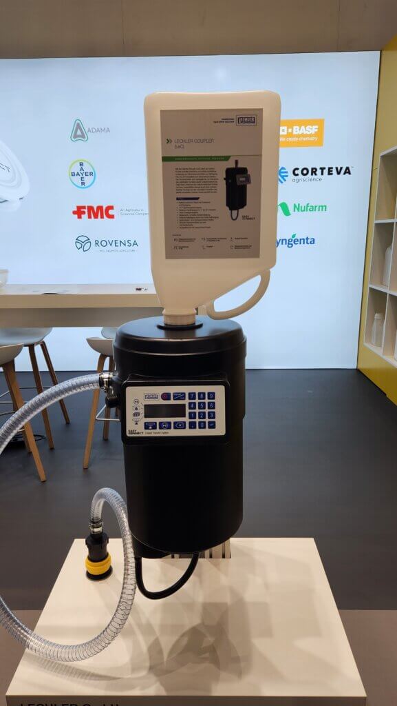
Lechler’s Coupler is compatible with the easyconnect cap and features more electrical automation in its design. It requires a 12V electric supply and creates suction (typically from the sprayer’s venturi) to draw out the chemical. A small metering motor automatically moves the probe that enters the container to adjust emptying rate. It employs a pressurized water line running at about 6 bar.
The system will be controlled via a smartphone app, where the operator can choose partial or full emptying of product containers and control the operating and rinsing processes. Rather than metering flow, the unit employs three load cells with vibration compensation to weigh product. Lechler claims this is more accurate (automatic dosing to a set volume with +/- 2.5% accuracy), because it can compensate for different product densities. The user manually enters these values from product SDS, but likely QR codes will be used in the future.
The system underwent further testing in 2024 and commercial availability is anticipated for 2025. Farmer’s Weekly covered the details of this system following Agritechnica 2023.
Aspects of Applied Biology 147, 2022 International Advances in Pesticide Application Review of ISO 21191 Closed Transfer Systems Performance Specifications. Nancy Westcott and Jan Langenakens.
This article was originally co-authored by Mick Roberts (Owner/Editor of Pro Operator Magazine) with significant contributions from Jan Langenakens (Principal at AAMS) and informed by insightful communications with both users and manufacturers of CTS. It has been updated as of January, 2025.
Tank mixing is the practice of combining multiple registered agricultural products in the sprayer tank for application in a single pass.
The Pros of Tank Mixing
Efficiency: If the timing makes sense, a single pass saves time and reduces trample/compaction. E.g. A “weed-and-feed” application of fertilizer and herbicide in corn.
Resistance management: Multiple modes of action help prevent resistance development and combat existing problems.
Improved performance: Labels may require adjuvants to condition carrier water or reduce drift (utility adjuvants) or to improve the degree of contact between droplets and the plant surface, or enhance product uptake or rainfastness (activator adjuvants).
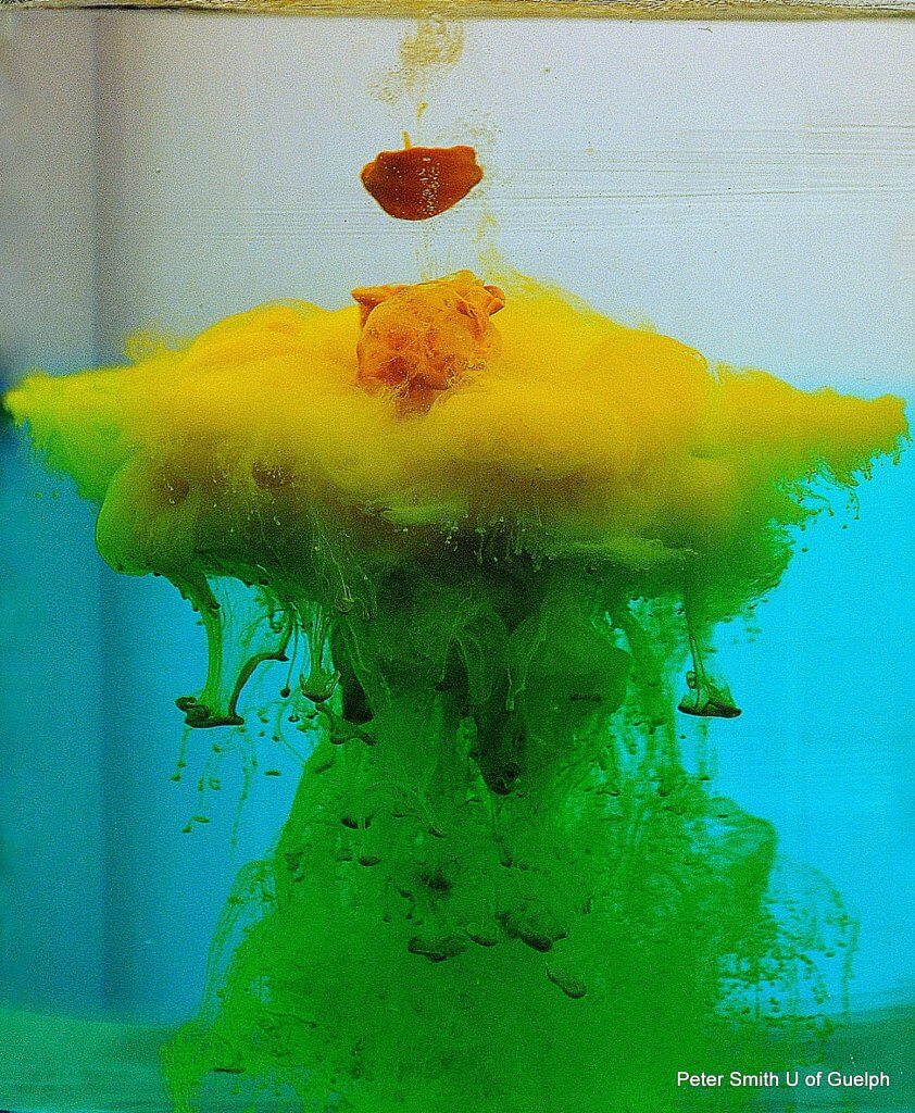
Prowl meets Roundup – A beautiful photo by Peter Smith, University of Guelph
The Cons of Tank Mixing
Tank mixing requires caution and careful investigation. Should tank mix partners prove to be incompatible, the consequences can be subtle or dramatic, but are always negative. There are two kinds of incompatibility.
1. Biological or Chemical Incompatibility
This form of incompatibility may not be immediately apparent following an application. Some level of crop damage or impaired efficacy occurs, which may impact yield or warrant an additional “clean-up” application. This is the result of product synergism or antagonism.
Synergism (Crop damage)
When products synergize, the application becomes too potent. For example, an adjuvant could affect crop retention or uptake, exposing it to more active ingredient or overwhelming crop metabolism. The result is damage to the crop we are trying to protect.
Antagonism (Reduced efficacy)
When products antagonize, the application becomes less potent. There are several examples:
pH adjusters in one product may reduce the half-life
of another product (e.g. The fungicide Captan has a half-life of 3 hours at a
pH of 7.1 and only 10 minutes at a pH of 8.2.)
Active ingredients may get tied-up on the clay-based
adjuvants in other products (e.g. glyphosate tied up by Metribuzin).
One product changes the uptake/retention of another.
For example, a contact herbicide burns weed foliage beyond its ability to take
up a lethal dose of systemic herbicide.
2. Physical Incompatibility
Physical incompatibility affects work rate and efficacy. Products form solids that interfere with, or halt, spraying. It can also make sprayer clean-up more difficult. For example, weak-acid herbicides lower the pH of the spray mix, reducing the solubility of Group 2 herbicides (i.e. imidazolinones, sulfonylureas, sulfonanilides). The oily formulation then adheres to plastic and rubber surfaces in tanks, connectors and hoses.
There are many forms of physical incompatibility:
Liquids can curdle into pastes and gels that clog plumbing to such an extent that flushing cannot clear it and a manual tear down is required.
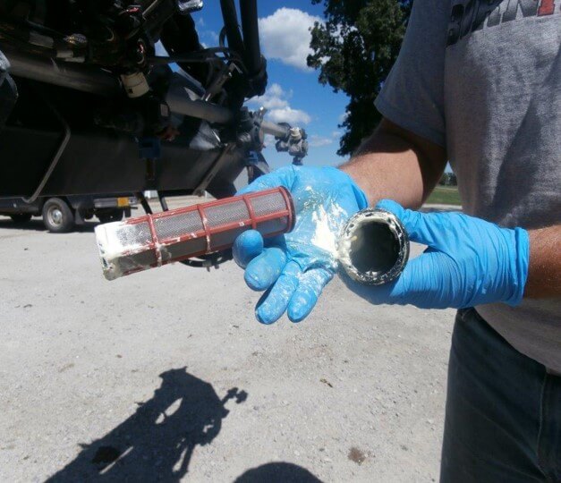
Clogged screens
Dry formulations don’t hydrate or disperse, becoming sediment that clogs screens and nozzles. Even if they are small enough to spray, they reduce coverage uniformity. For example, a dry product added behind an oil gets coated, preventing it from hydrating.
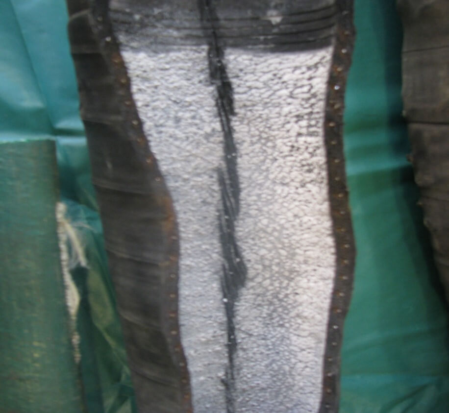
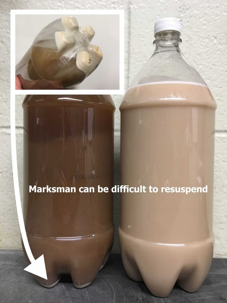
Certain product combinations may cause settling, or one partner is more prone to settling. If the sprayer sits without agitation, settled products may or may not resuspend. Even if they do resuspend in the tank, they may remain as sediment in lines.
Residue in hoses – Photo courtesy of Fred Whitford, Purdue UniversityClay-based products may or may not resuspend easily in a tank. Even then, they may not resuspend in plumbing lines.
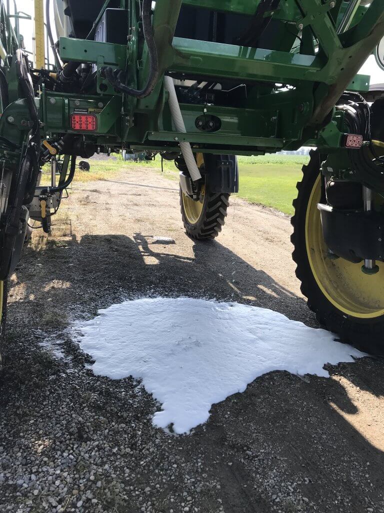
Certain product combinations may cause foaming, or one partner may be prone to foaming, causing overflows or breaking pump suction. When products foam, dry products added through the foam may swell, preventing hydration.
The Foamover Blues
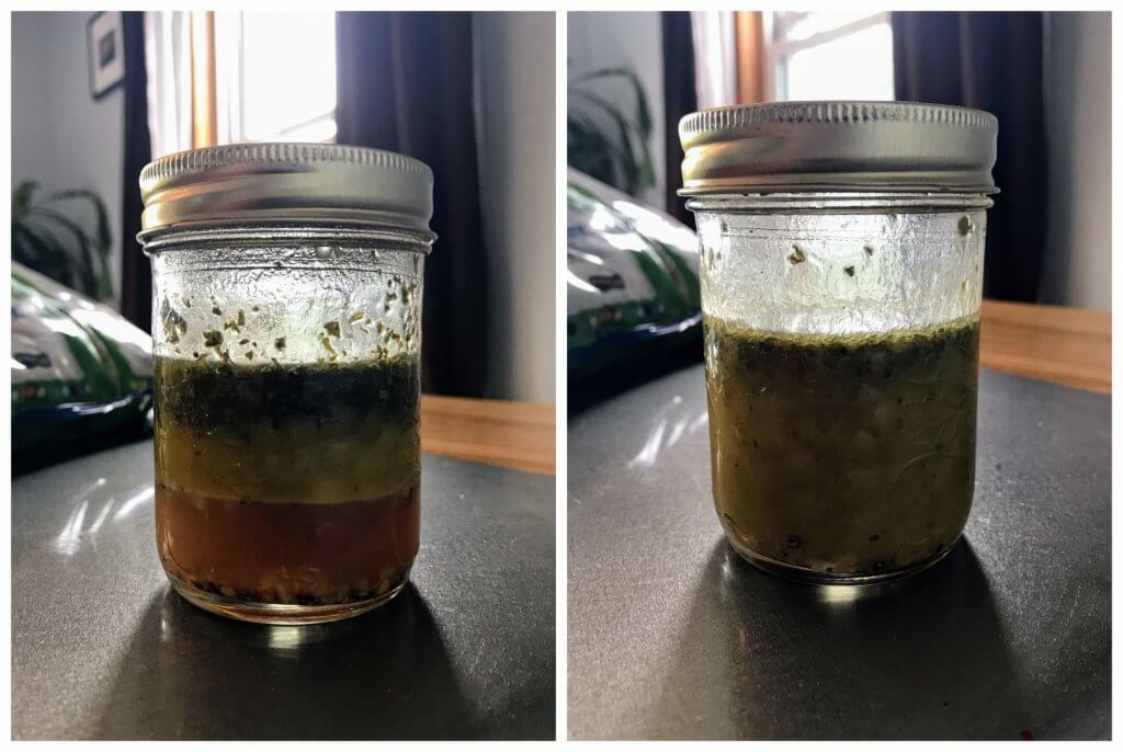
Phase separation occurs when products layer in the tank. Consider oil and water. Even with agitation, the active ingredients may not be uniformly suspended in the tank and coverage uniformity will be reduced during spraying.
Salad dressing left to rest is a great example of separation and stratification (left). Agitation helps emulsify it (right)
Due Diligence – Preventing Tank Mixing Errors
Incompatibility is often a function of the inert ingredients in pesticide formulations (e.g. thickeners, adjuvants, defoamers, stabilizers, solvents, etc.) and not the active ingredients. The more products you add to the tank, the more likely you’ll encounter an issue. It is prudent to perform a jar test to confirm physical compatibility. Remember, even if registered tank mix partners support mixing, your pace, mixing order, and water quality/temperature could cause issues.
Do not decide to try a new-to-you registered tank mix during loading. Even if you’ve used these products successfully in the past, formulations change without notice. Plan as much as possible off season when there is time to do the following:
Consult the pesticide labels
Pesticide
labels are always the first point of reference. They should be obeyed even if they
contradict conventional practices. Booklet-style labels that come with the
products are long, difficult to search and may not be up-to-date.
In Canada, it is faster and easier to go to the PMRA Label Search website and search labels in PDF format. In other countries, consult the manufacturer’s website for label information. For each tank mix partner, use <CTRL>+F to find the following keywords:
Do Not Mix
Mix
Hours
Agitation
Fertilizers
Consult manufacturer and crop advisors
You’re likely not the first to consider a certain tank mix. Learn from those that have been there already:
Consult your chemical sales representative. They
know their products best and want to see you succeed. They may have insight that
is not found on the product label.
Consult local government or academic extension
programs for an unbiased opinion.
Enlist the help of a professional crop advisor.
It is a good practice to get tank mix recommendations in writing. If something should go wrong, liability is an important concern.
If you’ve made a mess – The Reverse Jar Test
It
happens. We’ll use this real-world situation as an example:
“I mixed up a batch of MCPA 500 A and Glyphosate at ¾ recommended label rate, but then got delayed on application with a stuck drill. I came back to the sprayer and found a nasty chemical precipitate – like waxy chunks. Agitation didn’t break them down. I dumped the tank out as I didn’t want to pump it through the booms. How do I clean up the chunks in the system?”
We forwarded
this question to ag chemists Dr. Eric Spandl (Land of Lakes) and Dr. Jim Reiss
(Precision Laboratories) and developed this response:
“Wearing appropriate personal protective equipment, physically remove the “chunky” material. A lot of time can be wasted (and rinsate water created) by experimenting with various concoctions, but if you do choose to try a compatibility agent, first try it in a mason jar. If it works to dissolve the material, it can be added to the tank with water and agitated. If not, you are down to manual cleaning: hot water under pressure.”
We dubbed this process “The Reverse Jar Test”. Do not add hot water, cleaners or compatibility agents until the reverse jar test confirms success. You may create a larger problem. Of course, the best advice is to not put yourself in this position to begin with. Once again, don’t make mixing decisions at the inductor bowl – make them before ordering product.
Tank mixing regulations in Canada (January, 2025 update)
The following legislative framework is specific to Canada, so readers in other countries should consult their own regulatory authorities.
Paragraph 6(5)(b) of the Pest Control Products Act (PCPA) states that no person shall use a pest control product in a way that is inconsistent with the directions on the label. In 2020, a public consultation was held to consolidate and clarify tank mixing requirements. This led to Regulatory Proposal PRO2020-01 (Streamlined Category B Submissions and Tank Mix Labelling – July 3, 2020). Essentially, it stated that tank mixing would be allowed if there was text on the product label that specifically permitted it. This could be a specific tank mix combination, a general statement permitting mixing, or both.
A new general label statement that permits tank mixing was proposed to consolidate tank mixing information in one place on the label and allow greater flexibility in terms of tank mixing options. The prohibition against tank mixing products with the same mode of action was removed, and the reference to tank mixing with a fertilizer is now an optional component of that statement. The general label statement reads as follows:
“This product may be tank mixed with (a fertilizer, a supplement, or with) registered pest control products, whose labels also allow tank mixing, provided the entirety of both labels, including Directions For Use, Precautions, Restrictions, Environmental Precautions, and Spray Buffer Zones are followed for each product. In cases where these requirements differ between the tank mix partner labels, the most restrictive label must be followed. Do not tank mix products containing the same active ingredient unless specifically listed on this label.
In December of 2022, Health Canada released a guidance document describing the federal tank mixing policy. This document is not part of the PCPA, but is an administrative document intended to facilitate compliance by all stakeholders. Registrants have until December, 2025 to update their extension material to align with amended product labels and guidance documents. Similarly, users of pest control products will be provided the same transitional period to adjust their purchasing and production practices to align with the provisions of this document. This means the policy will be in full effect on December , 2025. After that, applicators in Canada can only apply tank mixes that appear specifically on a product label, or tank mixes of products whose labels include the new general tank mixing statement.
Summary of the guidance document
Tank mixing is not permitted when a potential tank mix partner’s label has some exclusionary statement, such as:
Forbidding mixing. E.g. “Do not mix or apply this product with any other additive, pesticide or fertilizer except as specifically recommended on this label.”
Limiting tank mixes to only those specifically listed on the product label.
During the label transition, guidance relating to tank mixing may be found under a section specific to tank mixing, and/or under other sections as in the following examples:
Directions for use: E.g. “When tank-mixes are permitted, read and observe all label directions, including rates and restrictions for each product used in the tank-mix. Follow the more stringent label precautionary measures for mixing, loading and applying stated on both product labels.”
Buffer Zones: E.g. “When tank mixes are permitted, consult the labels of the tank-mix partners and observe the largest (most restrictive) spray buffer zone of the products involved in the tank mixture and apply using the coarsest spray (ASABE) category indicated on the labels for those tank mix partners.”
Resistance Management: E.g. “Use tank mixtures with [fungicide/bactericides/insecticides/acaricides] from a different group that is effective on the target [pathogen/pest] when such use is permitted.”
If there are no directions on the labels, don’t tank mix them.
If your situation does not fit these examples, the following table (Appendix A at the bottom of the Guidance Document), lists several other examples examples of different tank mix wording scenarios for registered pest control products.
Table 1: Permissibility of tank mixing based on various combinations of label statements related to tank mixing
Product X label says
Product Y label says
Can I tank mix? (Y/N)
Nothing (silent on tank mixing)
Nothing (silent on tank mixing)
N
General tank mix statement
Nothing (silent on tank mixing)
N
Nothing (silent on tank mixing)
General tank mix statement
N
General tank mix statement
General tank mix statement
Y
General tank mix statement
Tank mix with Product X
Y
Tank mix with Product Y
General tank mix statement
Y
Tank mix with Product Y
Nothing (silent on tank mixing)
Y
Nothing (silent on tank mixing)
Tank mix with Product X
Y
Tank mix with Product Y
Tank mix with Product X
Y
Tank mix with Product Y
Exclusionary statement (and label does not include a specific Product X tank mix)
N*
Exclusionary statement (and label does not include a specific Product Y tank mix)
Tank mix with Product X
N*
*There may be registered labels that have tank mix scenarios like this. Note that this is not allowed for new tank mix label amendments. Further, any product labels that have tank mix scenarios like this must be amended to alleviate the contradictory scenario. To do this, using the last scenario in Table 1 as an example, one of the following must occur: 1) remove the Product X tank mix from the Product Y label, 2) remove the exclusionary statement from the Product X label, or 3) add a specific tank mix for Product Y on the Product X label. Source: PMRA Guidance Document Tank Mix Labelling 2023
Tank mixing adjuvants
According to the PMRA, the rules surrounding the tank mixing of adjuvants remain the same as they have been since 2009, and are not included under the new guidance document. While the PCPA does not reference adjuvants specifically, they are prescribed to be pest control products in the regulations (Pest Control Products Regulations s.2(b)). The general reference in the PCPA that applies is s.6(5)(b).
Therefore, in the case of activator adjuvants, the label for at least one tank mix partner must specify the use of an adjuvant, and only registered adjuvants labeled for the crop and for tank mixing are permitted. For example, tank mixing the herbicide Reflex with a registered soybean oil adjuvant not labelled for the use, or with an unregistered food grade activator adjuvant, would not be acceptable. Utility adjuvants have registration numbers, but their use is not prescribed or specified on pesticide labels, leaving their use to the discretion of the operator.
For more information on Canada’s Tank Mixing Policy
In late 2022, Australia’s GRDC released a comprehensive guide on pesticide mixing and batching (within the context of the Australian agronomic environment, of course), which can be downloaded for free, here.
Finally, you can watch a 2021 presentation on tank mixing (below). It was delivered to a grape growing audience, but much of the content applies across agriculture. There are a few “oops” moments where I didn’t say quite what I meant. I misread the Sencor dissolution / filtration work. And, I really didn’t answer the last question about mixing herbicides. The answer should have been to consult labels and local resources, such as OMAFRA’s Crop Protection Hub. Note that any discussion of Canadian regulatory policy may have changed in light of the new 2022 Guidance Document.
This article was co-written with Mike Cowbrough, OMAFRA Weed Management Specialist – Field Crops
It’s odd to begin an article by suggesting the reader consult another, but Dr. Tom Wolf wrote a great summary about adjuvants for SaskPulse in 2023 and you can and should download it here. While I’m at it, also grab this article by Rich Zollinger, Emeritus Extension Weed Scientist, North Dakota State University.
OK, back to the article at hand. An adjuvant is “any substance in a formulation or added to the spray tank to modify the biological activity or application characteristics”. This means they have an array of functions, such as masking pesticide odor, conditioning carrier water, improving mixing and reducing drift (Utility modifier adjuvants). They can also improve the degree of contact between droplets and the plant surface, or enhance product uptake or rainfastness (Activator adjuvants which include a subset of products referred to as Surfactants [SURFace ACTive agENTS]).
For example, this short video was filmed in 2015 to demonstrate how a sticker surfactant reduces runoff and how a penetrant surfactant can help a product pass through a waxy plant surface. This video was filmed and edited by former OMAFA summer student, Victoria Radauskas.
Generally, pesticides already come preformulated with the requisite inerts, which include the utility modifier and activator adjuvants that ensure ease of use and optimal product performance. But sometimes the pesticide label requires the operator to add a particular name brand or category of adjuvant. In this case, the pesticide does not include the adjuvant because it might negatively impact product stability, increase bulk and/or increase expense.
Canada is seeing an increase in the number of adjuvants for purchase (particularly utility modifiers). Claims of improved performance make it tempting to reflexively and proactively throw them in the mix. The grower is free to use any adjuvant provided it is registered for use on the crop and in combination with the pesticide being applied. You can learn more about the regulatory realities in our tank mix article.
We suggest that adding any adjuvant is an optional last step in optimizing a sprayer’s performance. Dialing in all other aspects tend to reap the greatest rewards. Here are a few general guidelines when using surfactants in horticultural crops:
Do not use penetrant surfactants (including oils) with copper, sulphur or captan fungicides.
Do not use penetrant surfactants with contact or surface pesticides.
Stickers may impede the movement of systemic products.
Stickers may prevent redistribution to newly emerging leaves early in the growing season (but they may be desirable during wet springs).
Deposition utility modifiers may negatively affect canopy penetration when employing multi row or alternate row traffic patterns.
Spreaders are more likely to incur runoff so adjust volumes accordingly.
Additional Resources
The following video presentation was recorded for a 2021 adjuvant conference in Argentina. It’s a primer to introduce what adjuvants are and why we might consider using them. You’ll note that I speak slowly during the presentation – that’s because it was being translated and I wanted to make that process as easy as possible. Also, I think I mistakenly said captan was an insecticide – in fact it’s a fungicide. Oops.
And here’s a 2022 interview from Real Agriculture’s “The Agronomists” featuring Tom Wolf of Agrimetrix, and Greg Dahl of Winfield United. For the adjuvant-related part of the conversation, you can pan ahead to the six-minute mark.
And here’s a 2025 interview from Real Agriculture’s “The Agronomists” featuring Jason Deveau and and Austin Anderson of Helena.
The concept of Air Displacements was developed by Dr. David Manktelow, Applied Research and Technologies Ltd.
What is the “right” speed to drive when spraying?
Airblast sprayer operators must know their average travel speed to calculate how much pesticide and time is required to complete a spray job. Note that it’s an average, not a constant, because travel speed is significantly affected by ground surface conditions (e.g. slippage), grade (e.g. hills) and the weight of the rig (e.g. as spray mix is depleted).
The pursuit of productivity and the unchallenged status quo of traditional spray volumes, blinds many operators to the fact that travel speed is a critical factor in focusing air energy on the target canopy. As long as droplets are small enough to be entrained and directed by the air, we believe that optimizing the fit between air energy and the target canopy leads to the most frugal and effective use of spray mix and should therefore dictate travel speed. If that speed proves to be painfully slow, or terrifyingly fast, then a mismatch is revealed between the sprayer design and the operational conditions and the overall spraying strategy should be reconsidered.
This article describes a method for modelling an ideal travel speed. It can be used as a sanity check for existing operations or for those seeking to evaluate the fit of a new airblast sprayer. However, this method can only approximate travel speed. A true optimization of sprayer settings will require fine tuning using the ribbon method and, ultimately, coverage feedback from water sensitive paper (see here and an older article here). We’ll begin with how to measure average travel speed.
How to measure average travel speed
Beware the tractor speedometer or rate controller that monitors wheel rotations; both can be fooled by changes in wheel size, tire wear or slippage. GPS or radar-based speed sensors are the most accurate method.
Those that prefer a manual method can follow this classic protocol for determining average travel speed:
Go to a row that is representative of the terrain in your planting. Measure out a distance of 50 m (150 ft) and mark the start and finish positions with wire marker flags.
Fill the sprayer tank half full of water.
Select the gear and engine speed in which you intend to spray. If using a pull-behind sprayer, ensure the PTO is running or you could introduce errors.
Bring the sprayer up to speed for a running start and begin timing as the front wheel passes the first flag. This is far easier when there are two people.
Stop the timer as the front wheel passes the second flag.
Stay out of any ruts and run the course two more times.
Determine the average drive time for the three runs (i.e. the sum of all three times in seconds divided by three).
Finally, calculate travel speed using one of the following formulae, depending on preferred units:
Ground Speed (km/h) = Average drive time for 50 m (s) ÷ 13.9 (a constant)
Those that prefer a less accurate but convenient hack can download any smartphone speedometer app that can calculate an average (similar to a runner’s GPS wristwatch). Fill the sprayer tank half full and drive a representative section of your operation with the fan on and the spray off. Consult the phone for your average speed for each pass. Take a screen shot and email it to yourself as a time-stamped component of your spray records.
The “Air Displacements” method
Dwell time
Airblast sprayers use fans to move a volume of air at a certain speed, often measured in m3/hr or ft3/min. Imagine that volume of air as a three dimensional shape extending from the air outlet over a distance. Likewise, imagine the void between the sprayer outlet and the target canopy as a three dimensional shape penetrating roughly halfway into that canopy (assuming we intend to spray every row).
How long must the sprayer dwell in one spot before it pushes all the intervening air out of the way and replaces it with spray-laden air? If the sprayer drives too slowly, it will wastefully push spray through and beyond the target (i.e. blow-through). If the sprayer moves too quickly, the spray will not have an opportunity to penetrate the target canopy and most certainly not reach the highest point. This concept of focusing air energy using travel speed is called Dwell Time.
We want to calculate the volume of air the sprayer generates, compare that to the volume we want displaced, and then determine how fast we must drive to optimize the fit. We can do all this with a tape measure, an anemometer, and a partner to record the data and do a little math.
1. Measure air outlet area
With the sprayer safely off, measure the area of the air outlet(s) on one side of the sprayer. We’ll use a Turbomist 30P Low Drift Tower (below) as an example. There are two air outlets that are 5 cm wide by 150 cm high for a total area of 0.075 m2 on each side. Be sure to look inside the outlet for any irregularities like baffles or obstructions intended to block air. Subtract those areas from the total. Don’t worry about small things like nozzle bodies.
For rectilinear outlets: Height (m) x width (m) = Area (m2)
For circular outlets: 3.14 x radius2 (m) = Area (m2)
The air outlet on this Turbomist 30P Low Drift tower sprayer is 5 cm wide by 150 cm tall for a total area of 0.075 m2.
2. Measure air speed
First, a few safety warnings: High speed air is loud and can carry debris, so always wear ear and eye protection and respect the hazards inherent to working with air-assist sprayers. Only use an anemometer rated for at least 160 km/h (100 mph) (e.g. here). Do not use a handheld weather meter such as a Kestrel because the impellor could be destroyed and become dangerous shrapnel.
Use an anemometer rated for at least 160 km/h (100 mph) (e.g. here). Do not use a handheld weather meter such as a Kestrel because the impellor could be destroyed and become dangerous shrapnel.
Bring the fan up to speed and holding the meter about 25 cm (10 in.) from the outlet, measure the air speed at several locations along the air outlet both vertically and horizontally. We calculate an average speed because many air outlets do not produce uniform air speed or volume along their outlets. For this example, we measured four locations along the air outlet on both sides of the sprayer and saw significant differences. We did this both in low and high gear (see table below).
High Gear
High Gear
Low Gear
Low Gear
Location Along Outlet
Left Side (m/s)
Right Side (m/s)
Left Side (m/s)
Right Side (m/s)
Top 1/4
41.1
80.3
42.9
24.6
Upper
34.9
32.2
26.4
30.8
Lower
30.8
30.0
24.0
26.4
Bottom 1/4
33.5
40.2
26.8
31.3
Average
35.1
45.7
30.0
28.3
Anemometer readings from the low drift tower sprayer outlets, on left and right side, in high and low fan gear. Four readings from bottom to top to determine the average. Readings taken 25 cm from edge of outlet and PTO set to 540 rpm.
Multiple air outlets
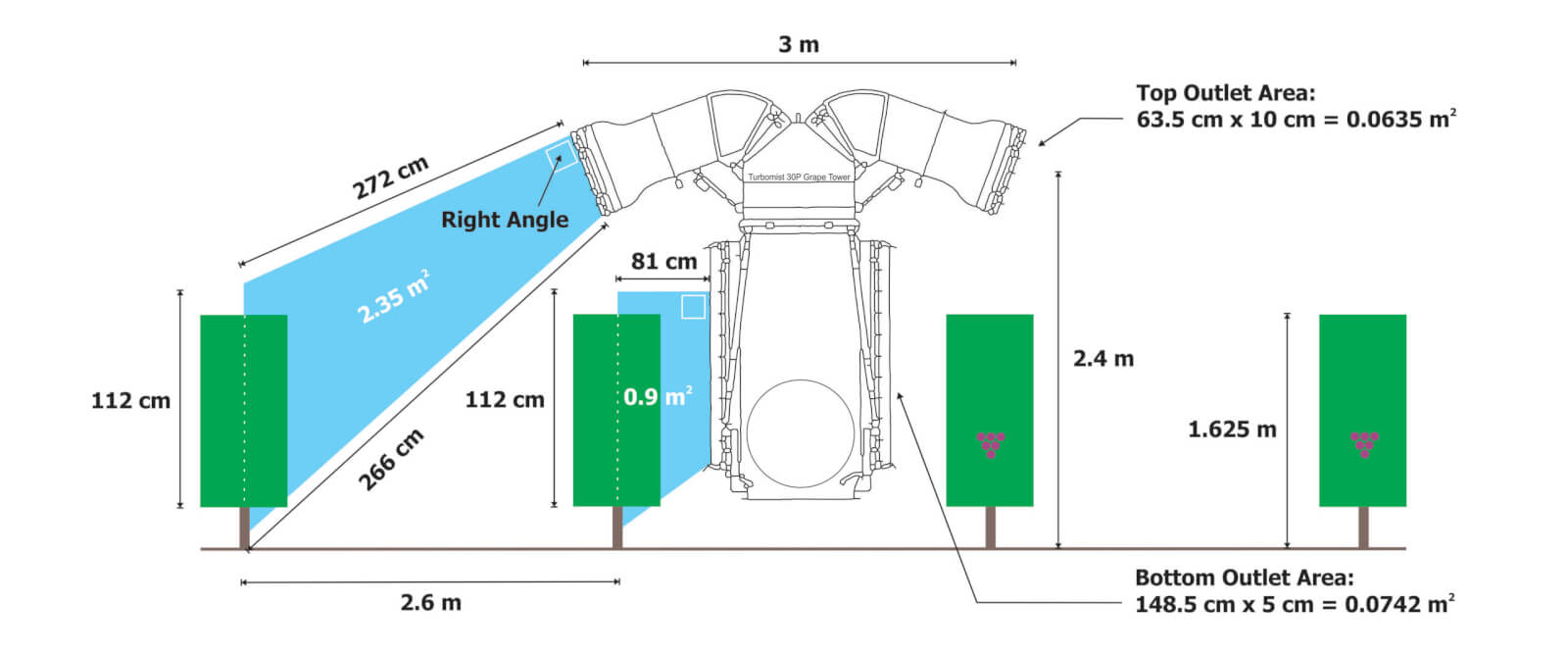
Before we continue with the method, let’s change sprayers to this Turbomist 30P Grape Tower (below). The design is intended to spray adjacent rows from the vertical outlets (5 cm x 150 cm = 0.075 m2) along the tower. The upper, inverted outlets (10 cm x 63.5 cm = 0.0635m2) throw spray over the adjacent rows and cover the outside rows. The intention is to improve productivity by covering four rows of grape (or possibly three) per pass.
The Turbomist 30P Grape Tower Sprayer is a multirow system intended to drive every third or fourth row.Lower, vertical ducts are 5 cm x 150 cm = 0.075 m2Upper, inverted ducts are 10 cm x 63.5 cm = 0.0635m2
However, when we consider this design through the Air Displacement lens, it’s almost like having two sprayers performing two jobs simultaneously. The vertical outlets and the upper, inverted outlets are different shapes. Further, their position (distance and angle, as the top outlets are angled back more aggressively) relative to their respective target canopies are significantly different. How fast must this sprayer drive to optimize the fit? Do we have to compromise coverage and incur drift and waste from one set of outlets to accommodate the other set? The manufacturer has worked to address this potential issue by partitioning the majority of the air energy to the top outlets, but let’s see how that affects travel speed.
3. Total volumetric flow
Having already measured the outlet area, we then measured average air speed (see table below).
High Gear
High Gear
Low Gear
Low Gear
Location Along Outlet
Left Side (m/s)
Right Side (m/s)
Left Side (m/s)
Right Side (m/s)
Top Outlet
27.0
26.5
27.0
26.0
Bottom Outlet
12.0
13.0
10.5
12.5
Average anemometer readings (n=4) for top and bottom outlets, on left and right side, in high and low fan gear. Readings taken 25 cm from edge of outlet and PTO set to 540 rpm.
Now we can use these two values to determine how much air the sprayer generates by calculating total volumetric flow. We first have to convert air speed from m/s to m/h to make the units work, so just multiply it by 3,600. Then we multiply that by the outlet area and we get the table below.
Average air speed (m/s) x 3,600 (a constant) = Average air speed (m/h)
Average air speed (m/h) x Outlet area (m2) = Total volumetric flow (m3/h)
High Gear
High Gear
Low Gear
Low Gear
Location Along Outlet
Left Side (m3/h)
Right Side (m3/h)
Left Side (m3/h)
Right Side (m3/h)
Top Outlet
6,172.0
6,058.0
6,172.0
5,944.0
Bottom Outlet
3,240.0
3,510.0
2,835.0
3,375.0
Total volumetric flow for top and bottom outlets, on left and right side, in high and low fan gear, with PTO at 540 rpm.
4. Target volume to displace
Now that we know the volume of air the sprayer generates, let’s determine the volume of air we need to replace with that spray laden air. This is really the only tricky bit because you have to picture a cross section and then measure the shape. See the illustration below.
For the bottom outlet, it’s simple. The outlet is 81 cm from the grape panel and the grape panel is 112 cm high. We calculate the area of a rectangle by multiplying length by width, so:
Length (cm) x Width (cm) = Area (cm2)
However, the sprayer design makes the top outlet’s job trickier to figure out. This isn’t a rectangle, it’s a “quadrilateral”. We get this odd shape when either the sprayer outlet or the target canopy are significantly taller than the other. Fortunately this one has a right angle so we don’t have to brush off our high school trigonometry textbooks. Instead, we can lean on the internet using this link and plug in the values. As we can see below, the cross sectional areas spanning from the outlets and the middle of the target canopies are 0.9 m2 for the bottom outlet, and 2.35 m2 for the upper outlets.
This gives us a cross sectional area, but we need to convert that to a volume so we can compare the air generated to the air needed. To do that, we multiply the cross sectional area by 100 m, representing how much air would be needed over 100 m of row length. The formula and the results are presented below.
Cross sectional area (m2) x 100 m of row length = Target displacement volume (m3)
Outlet
Target Displacement Volume (m3)
Top Outlet
235.0
Bottom Outlet
90.0
Target displacement volume for each outlet over 100 m of canopy row.
5. Displacement rate
We see the target displacement volumes for each outlet are significantly different. Assuming the air from the upper outlet maintains its integrity and reaches its target canopy without being blown off course, it must produce enough air energy to fill more than twice the displacement volume of the lower outlet. We can see from the earlier calculations that it does produce almost twice the total volumetric flow. But is it enough? To know we must calculate the Displacement Rate for each outlet. Let’s just focus on the left side of the sprayer in high gear.
Displacement Rate (displacements/h) for left side of sprayerin high gear
Top Outlet
26.25
Bottom Outlet
36.0
Displacement rates for the outlets on the left side of the sprayer in high gear.
So we see that the outlets at the top of the sprayer, if stationary, could displace the target volume of air 26.25 times an hour. However, the lower outlet would displace its target volume 36 times in that same hour. We see that we might have a problem. But this is for a stationary sprayer and not a sprayer in motion. The last step gives us what we came here for.
6. Ideal travel speed
We can now determine the ideal travel speed for this sprayer using that same 100 m row length.
[Displacement rate (displacements/h) x 100 m of row length] ÷ 1,000 (a constant) = Ideal travel speed (km/h)
Outlet
Ideal travel speed (km/h) based on left side of sprayer
Top Outlet
2.6
Bottom Outlet
3.6
Ideal travel speed for each outlet on the left side of the sprayer in high gear.
As we stated at the beginning of this article, this is only a model. It doesn’t account for canopy density and assumes the spray laden volume of air produced by the sprayer can reach the target intact over a given distance. However it does indicate that there is a potential issue that will lead to either over spraying the adjacent row (slower travel speed) or under spraying the distant rows (faster travel speed) which could lead to waste, drift and poor coverage.
In the image below, we chose to drive close to 2.6 km/h in high gear. No effort was made to adjust the liquid flow (i.e. change the nozzles) so there was too much spray volume here, but we can see the losses on the left (upwind) side, and the blow-through three rows over on the right (downwind) side. Leaving aside the excessive liquid volume, we could drive faster or reduce the fan gear to reduce the blow-through on the adjacent rows, but we may go too fast (or reduce the rate of air displacement) for the upper outlets to reach the target. We can already see the integrity of the upper-left outlet breaking down as it sprays into the wind.
Testing a travel speed. No effort was made to adjust liquid flow, which is excessive here. Cross wind was from the left to the right in the image. Photo by Corey Parker (Instagram: _parkerproductions)
Take home
An ideal travel speed for an airblast sprayer is more than just being productive. The spray must reach and penetrate the target. If this requires dangerously high speeds, or if you simply can’t move slowly enough, it suggests a problem with the spraying strategy. Changes will have to be made to the sprayer, the target canopy, or even the weather conditions you’re willing to spray in. Getting the job done quickly should not compromise the quality of the job. Use this method to re-evaluate your practices, or to assess the capabilities of candidate sprayers if you’re considering a new purchase. Be sure to confirm what this model is telling you using some coverage indicator, such as water sensitive paper.